


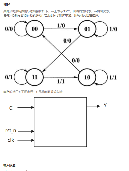
VL22 根据状态转移图实现时序电路
思路一:
`timescale 1ns/1ns

module seq_circuit(
   input                C   ,
   input                clk ,
   input                rst_n,

   output   wire        Y
);

reg [1:0] state , new_state;

parameter s0 = 2'b00;
parameter s1 = 2'b01;
parameter s2 = 2'b10;
parameter s3 = 2'b11;

always @( *) begin
        case(state)
        s0 : new_state = C ? s1 : s0;
        s1 : new_state = C ? s1 : s3;
        s2 : new_state = C ? s2 : s0;
        s3 : new_state = C ? s2 : s3;
        default : new_state = state;
        endcase
end

always @( posedge clk , negedge rst_n) begin
    if(!rst_n)
        state <= s0;
    else
        state <= new_state;
end
assign Y = ((state == s3 | (state == s2 & C== 1))&(rst_n == 1'b1)) ? 1 : 0;
endmodule
注意的是:
1.new_state 的计算是组合逻辑,要用 = 。
2.在s2状态时候,Y和C有关系。
3.清晰的两段式结构,一个always块计算new_state,另一个always块完成state的变化。
思路二:
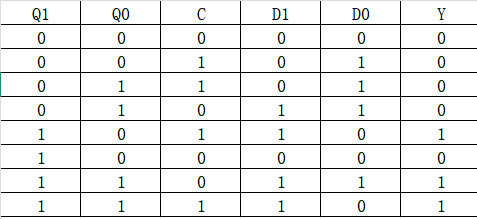
找出等于1的各项式子,加起来,写出来,可以求得:
D1 = Q1&Q0 | ~Q1&Q0&(~C) | Q1 & ~Q0 &C ;
D0 = ~Q1 & ~Q0 & C |~Q1&Q0 |Q1&Q0& ~C;
Y = Q1&Q0 | Q1&~Q0&C;
代码如下:
`timescale 1ns/1ns
module seq_circuit(
   input                C   ,
   input                clk ,
   input                rst_n,

   output   wire        Y
);

reg Q1,Q0;
wire D1,D0;
always @ (posedge clk , negedge rst_n) begin
    if(!rst_n) begin Q1<= 0;Q0<= 0 ;end
    else begin
        Q1 <= D1;
        Q0 <= D0;
    end

end
assign D1 = Q1&Q0 | ~Q1&Q0&(~C) | Q1 & ~Q0 &C ;

assign D0 = ~Q1 & ~Q0 & C |~Q1&Q0 |Q1&Q0& ~C;

assign Y = Q1&Q0 | Q1&~Q0&C;
endmodule
思路二的另一种写法:
`timescale 1ns/1ns

module seq_circuit(
   input                C   ,
   input                clk ,
   input                rst_n,

   output   wire        Y
);
reg Q1,Q0;
always @ (posedge clk , negedge rst_n) begin
    if(!rst_n) begin Q1<= 0;Q0<= 0 ;end
    else begin
        Q1 <= Q1&Q0 | ~Q1&Q0&(~C) | Q1 & ~Q0 &C ;
        Q0 <=  ~Q1 & ~Q0 & C |~Q1&Q0 |Q1&Q0& ~C;
    end
end
assign Y = Q1&Q0 | Q1&~Q0&C;
endmodule
去掉D1,D0更简洁。


 1436
1436

 被折叠的 条评论
为什么被折叠?
被折叠的 条评论
为什么被折叠?
 到【灌水乐园】发言


