


- 模拟I2C驱动BMP280气压传感器
- 模拟SPI
- CAN通信
模拟I2C驱动BMP280气压传感器
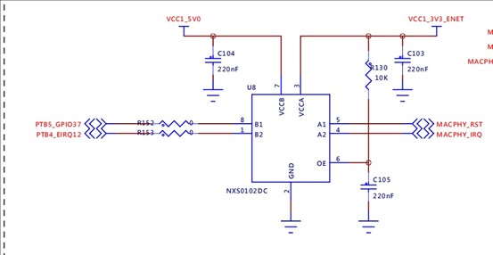
模拟I2C没什么好说的,只需要三个GPIO功能即可:设置SDA引脚的输入以及输出方向,设置SCL SDA引脚的输出高低电平,读取SDA引脚的输入值,直接 将要用到的SCL和SDA引脚初始化为GPIO即可:
![]()
用到了开发板上的PTB5和PTB4,这两个引脚经过了一个电平转换芯片,高电平为3.3V:
直接上代码:
#define FAKE_I2C_SCL_PTB5_HIGH Siul2_Dio_Ip_WritePin(FAKE_I2C_SCL_PORT , FAKE_I2C_SCL_PIN , 1);

#define FAKE_I2C_SCL_PTB5_LOW Siul2_Dio_Ip_WritePin(FAKE_I2C_SCL_PORT , FAKE_I2C_SCL_PIN , 0);


#define FAKE_I2C_SDA_PTB4_HIGH Siul2_Dio_Ip_WritePin(FAKE_I2C_SDA_PORT , FAKE_I2C_SDA_PIN , 1);

#define FAKE_I2C_SDA_PTB4_LOW Siul2_Dio_Ip_WritePin(FAKE_I2C_SDA_PORT , FAKE_I2C_SDA_PIN , 0);


#define FAKE_I2C_SDA_PTB4_IN Siul2_Port_Ip_SetPinDirection(PORTB_L_HALF , 4 , SIUL2_PORT_IN);

#define FAKE_I2C_SDA_PTB4_OUT Siul2_Port_Ip_SetPinDirection(PORTB_L_HALF , 4 , SIUL2_PORT_OUT);


#define I2C_SDA_PTB4_READ Siul2_Dio_Ip_ReadPin(FAKE_I2C_SDA_PORT , FAKE_I2C_SDA_PIN)


void Fake_I2C_Idle_PTB5_PTB4()

{

FAKE_I2C_SDA_PTB4_OUT;

FAKE_I2C_SDA_PTB4_HIGH;

FAKE_I2C_SCL_PTB5_HIGH;

Pit0_Delay_us(4);

}


void Fake_I2C_Start_PTB5_PTB4(void)

{

FAKE_I2C_SDA_PTB4_OUT;

FAKE_I2C_SDA_PTB4_HIGH;

FAKE_I2C_SCL_PTB5_HIGH;

Pit0_Delay_us(4);

FAKE_I2C_SDA_PTB4_LOW;

Pit0_Delay_us(4);

FAKE_I2C_SCL_PTB5_LOW;

Pit0_Delay_us(4);

}


void Fake_I2C_Stop_PTB5_PTB4(void)

{

FAKE_I2C_SDA_PTB4_OUT;

FAKE_I2C_SDA_PTB4_LOW;

FAKE_I2C_SCL_PTB5_HIGH;

Pit0_Delay_us(4);

FAKE_I2C_SDA_PTB4_HIGH;

}


uint8_t Fake_I2C_Wait_Ack_PTB5_PTB4(void)

{

uint8_t rvalue;

FAKE_I2C_SDA_PTB4_OUT;

FAKE_I2C_SDA_PTB4_HIGH;

Pit0_Delay_us(4);

FAKE_I2C_SCL_PTB5_HIGH;

Pit0_Delay_us(4);

FAKE_I2C_SDA_PTB4_IN;

if(I2C_SDA_PTB4_READ)

{

rvalue = 1;

}

else

{

rvalue = 0;

}

FAKE_I2C_SCL_PTB5_LOW;

Pit0_Delay_us(4);

return rvalue;

}


void Fake_I2C_Ack_PTB5_PTB4(void)

{

FAKE_I2C_SDA_PTB4_OUT;

FAKE_I2C_SDA_PTB4_LOW;

Pit0_Delay_us(4);

FAKE_I2C_SCL_PTB5_HIGH;

Pit0_Delay_us(4);

FAKE_I2C_SCL_PTB5_LOW;

Pit0_Delay_us(4);

FAKE_I2C_SDA_PTB4_HIGH;

}

void Fake_I2C_NAck_PTB5_PTB4(void)

{

FAKE_I2C_SDA_PTB4_OUT;

FAKE_I2C_SDA_PTB4_HIGH;

Pit0_Delay_us(4);

FAKE_I2C_SCL_PTB5_HIGH;

Pit0_Delay_us(4);

FAKE_I2C_SCL_PTB5_LOW;

Pit0_Delay_us(4);

}


void Fake_I2C_Send_Byte_PTB5_PTB4(uint8_t txd)

{

uint8_t i;

FAKE_I2C_SDA_PTB4_OUT;

FAKE_I2C_SCL_PTB5_LOW;

for(i = 0 ; i < 8 ; i ++)

{

if((txd & 0x80) >> 7)

{

FAKE_I2C_SDA_PTB4_HIGH;

}

else

{

FAKE_I2C_SDA_PTB4_LOW;

}

txd <<= 1;

Pit0_Delay_us(20);

FAKE_I2C_SCL_PTB5_HIGH;

Pit0_Delay_us(20);

FAKE_I2C_SCL_PTB5_LOW;

Pit0_Delay_us(20);

}

Pit0_Delay_us(20);

}


uint16_t Fake_I2C_Read_Byte_PTB5_PTB4(uint8_t ack)

{

uint8_t i;

uint16_t dat = 0;

FAKE_I2C_SDA_PTB4_IN;

for(i = 0 ; i < 8 ; i++)

{

FAKE_I2C_SCL_PTB5_LOW;

Pit0_Delay_us(20);

FAKE_I2C_SCL_PTB5_HIGH;

dat <<= 1;

if(I2C_SDA_PTB4_READ)

dat++;

Pit0_Delay_us(20);

}


if (!ack)

{

Fake_I2C_NAck_PTB5_PTB4();

}

else

{

Fake_I2C_Ack_PTB5_PTB4();

}

return dat;

}


uint8_t Fake_I2C_Read_Addr_PTB5_PTB4(uint8_t dev_addr , uint8_t reg)

{


uint8_t res;

Fake_I2C_Start_PTB5_PTB4();

Fake_I2C_Send_Byte_PTB5_PTB4((dev_addr << 1) | 0);

Fake_I2C_Wait_Ack_PTB5_PTB4();

Fake_I2C_Send_Byte_PTB5_PTB4(reg);

Fake_I2C_Wait_Ack_PTB5_PTB4();

Fake_I2C_Start_PTB5_PTB4();

Fake_I2C_Send_Byte_PTB5_PTB4((dev_addr << 1) | 1);

Fake_I2C_Wait_Ack_PTB5_PTB4();

res = Fake_I2C_Read_Byte_PTB5_PTB4(0);

Fake_I2C_Stop_PTB5_PTB4();

return res;

}


void Fake_I2C_Read_Datas_PTB5_PTB4(uint8_t dev_addr , uint8_t reg , uint8_t data_len , uint8_t data[])

{

while(data_len)

{

*data = Fake_I2C_Read_Addr_PTB5_PTB4(dev_addr , reg++);

data ++;

data_len --;

}

}


void Fake_I2C_Write_Reg_Data_PTB5_PTB4(uint8_t dev_addr , uint8_t reg , uint8_t data)

{

Fake_I2C_Start_PTB5_PTB4();

Fake_I2C_Send_Byte_PTB5_PTB4((dev_addr << 1) | 0);

Fake_I2C_Wait_Ack_PTB5_PTB4();

Fake_I2C_Send_Byte_PTB5_PTB4(reg);

Fake_I2C_Wait_Ack_PTB5_PTB4();

Fake_I2C_Send_Byte_PTB5_PTB4(data);

Fake_I2C_Wait_Ack_PTB5_PTB4();

Fake_I2C_Stop_PTB5_PTB4();

}


void Fake_I2C_Write_Reg_Datas_PTB5_PTB4(uint8_t dev_addr , uint8_t reg , uint8_t data_len , uint8_t data[])

{

int i;

Fake_I2C_Start_PTB5_PTB4();

Fake_I2C_Send_Byte_PTB5_PTB4((dev_addr << 1) | 0);

Fake_I2C_Wait_Ack_PTB5_PTB4();

Fake_I2C_Send_Byte_PTB5_PTB4(reg);

Fake_I2C_Wait_Ack_PTB5_PTB4();

for(i = 0 ; i < data_len ; i++)

{

Fake_I2C_Send_Byte_PTB5_PTB4(data[i]);

Fake_I2C_Wait_Ack_PTB5_PTB4();

}

Fake_I2C_Stop_PTB5_PTB4();

Pit0_Delay_ms(10);

}


#define ATH20_SLAVE_ADDRESS 0x38


#define BMP280_PRESSURE_OSR (BMP280_OVERSAMP_8X)

#define BMP280_TEMPERATURE_OSR (BMP280_OVERSAMP_16X)

#define BMP280_MODE (BMP280_PRESSURE_OSR << 2 | BMP280_TEMPERATURE_OSR << 5 | BMP280_NORMAL_MODE)


#define BMP280_SLAVE_ADDRESS_0x76 0x76

#define BMP280_SLAVE_ADDRESS_0x77 0x77


/*calibration parameters */

#define BMP280_DIG_T1_LSB_REG 0x88

#define BMP280_DIG_T1_MSB_REG 0x89

#define BMP280_DIG_T2_LSB_REG 0x8A

#define BMP280_DIG_T2_MSB_REG 0x8B

#define BMP280_DIG_T3_LSB_REG 0x8C

#define BMP280_DIG_T3_MSB_REG 0x8D

#define BMP280_DIG_P1_LSB_REG 0x8E

#define BMP280_DIG_P1_MSB_REG 0x8F

#define BMP280_DIG_P2_LSB_REG 0x90

#define BMP280_DIG_P2_MSB_REG 0x91

#define BMP280_DIG_P3_LSB_REG 0x92

#define BMP280_DIG_P3_MSB_REG 0x93

#define BMP280_DIG_P4_LSB_REG 0x94

#define BMP280_DIG_P4_MSB_REG 0x95

#define BMP280_DIG_P5_LSB_REG 0x96

#define BMP280_DIG_P5_MSB_REG 0x97

#define BMP280_DIG_P6_LSB_REG 0x98

#define BMP280_DIG_P6_MSB_REG 0x99

#define BMP280_DIG_P7_LSB_REG 0x9A

#define BMP280_DIG_P7_MSB_REG 0x9B

#define BMP280_DIG_P8_LSB_REG 0x9C

#define BMP280_DIG_P8_MSB_REG 0x9D

#define BMP280_DIG_P9_LSB_REG 0x9E

#define BMP280_DIG_P9_MSB_REG 0x9F


#define BMP280_CHIPID_REG 0xD0 /*Chip ID Register */

#define BMP280_RESET_REG 0xE0 /*Softreset Register */

#define BMP280_STATUS_REG 0xF3 /*Status Register */

#define BMP280_CTRLMEAS_REG 0xF4 /*Ctrl Measure Register */

#define BMP280_CONFIG_REG 0xF5 /*Configuration Register */

#define BMP280_PRESSURE_MSB_REG 0xF7 /*Pressure MSB Register */

#define BMP280_PRESSURE_LSB_REG 0xF8 /*Pressure LSB Register */

#define BMP280_PRESSURE_XLSB_REG 0xF9 /*Pressure XLSB Register */

#define BMP280_TEMPERATURE_MSB_REG 0xFA /*Temperature MSB Reg */

#define BMP280_TEMPERATURE_LSB_REG 0xFB /*Temperature LSB Reg */

#define BMP280_TEMPERATURE_XLSB_REG 0xFC /*Temperature XLSB Reg */


#define BMP280_SLEEP_MODE (0x00)

#define BMP280_FORCED_MODE (0x01)

#define BMP280_NORMAL_MODE (0x03)


#define BMP280_TEMPERATURE_CALIB_DIG_T1_LSB_REG (0x88)

#define BMP280_PRESSURE_TEMPERATURE_CALIB_DATA_LENGTH (24)

#define BMP280_DATA_FRAME_SIZE (6)


#define BMP280_OVERSAMP_SKIPPED (0x00)

#define BMP280_OVERSAMP_1X (0x01)

#define BMP280_OVERSAMP_2X (0x02)

#define BMP280_OVERSAMP_4X (0x03)

#define BMP280_OVERSAMP_8X (0x04)

#define BMP280_OVERSAMP_16X (0x05)


#define CONST_PF 0.1902630958

//(1/5.25588f) Pressure factor

#define FIX_TEMP 25

// Fixed Temperature. ASL is a function of pressure and temperature, but as the temperature changes so much (blow a little towards the flie and watch it drop 5 degrees) it corrupts the ASL estimates.

// TLDR: Adjusting for temp changes does more harm than good.


typedef struct

{

uint16_t dig_T1;/* calibration T1 data */

int16_t dig_T2; /* calibration T2 data */

int16_t dig_T3; /* calibration T3 data */

uint16_t dig_P1;/* calibration P1 data */

int16_t dig_P2; /* calibration P2 data */

int16_t dig_P3; /* calibration P3 data */

int16_t dig_P4; /* calibration P4 data */

int16_t dig_P5; /* calibration P5 data */

int16_t dig_P6; /* calibration P6 data */

int16_t dig_P7; /* calibration P7 data */

int16_t dig_P8; /* calibration P8 data */

int16_t dig_P9; /* calibration P9 data */

int t_fine; /* calibration t_fine data */

} bmp280Calib;


uint8_t msb , lsb , xlsb;

float var1 , var2;

bmp280Calib bmp280Cal;


uint8_t BMP280_Init(void)

{

uint8_t bmp280_id;

uint8_t tmp[1];


printf("BMP280_Init.\n");


Fake_I2C_Read_Datas_PTB5_PTB4(BMP280_SLAVE_ADDRESS_0x77 , BMP280_CHIPID_REG, 1, &bmp280_id);


printf("bmp280_id = 0x%x\n" , bmp280_id);


Fake_I2C_Read_Datas_PTB5_PTB4(BMP280_SLAVE_ADDRESS_0x77, BMP280_DIG_T1_LSB_REG , 24 , (uint8_t *)&bmp280Cal);


//printf("%d %d %d %d %d %d %d %d %d %d %d %d\n" ,

// bmp280Cal.dig_T1 , bmp280Cal.dig_T2 , bmp280Cal.dig_T3 ,

// bmp280Cal.dig_P1 , bmp280Cal.dig_P2 , bmp280Cal.dig_P3 ,

// bmp280Cal.dig_P4 , bmp280Cal.dig_P5 , bmp280Cal.dig_P6 ,

// bmp280Cal.dig_P7 , bmp280Cal.dig_P8 , bmp280Cal.dig_P9);


tmp[0] = BMP280_MODE;

Fake_I2C_Write_Reg_Datas_PTB5_PTB4(BMP280_SLAVE_ADDRESS_0x77 , BMP280_CTRLMEAS_REG , 1 , tmp);


tmp[0] = 5 << 2;

Fake_I2C_Write_Reg_Datas_PTB5_PTB4(BMP280_SLAVE_ADDRESS_0x77 , BMP280_CONFIG_REG , 1 , tmp);


return bmp280_id;

}
连接BMP280到开发板,观察BMP280读数:

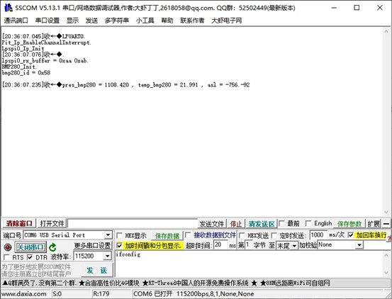
但是发现了一个问题,使用printf函数,无法打印浮点数,只能通过整形方式强转,并且使用abs()函数会卡死:
BMP280_Read_Pressure_Tempature(&bmp280_pres , &bmp280_temp);

asl = BMP280PressureToAltitude(&bmp280_pres);

printf("pres_bmp280 = %d.%-3d , temp_bmp280 = %d.%-3d , asl = %d.%-3d\n" ,

(int)bmp280_pres , ((int)(bmp280_pres * 1000)) % 1000 ,

(int)bmp280_temp , ((int)(bmp280_temp * 1000)) % 1000 ,

(int)asl , ((int)(asl * 1000)) % 1000

);
这个原因跟编译器和编译器选项有关,不深究。
1. 模拟SPI
由于开发板的硬件SPI波形调试一直不顺利:
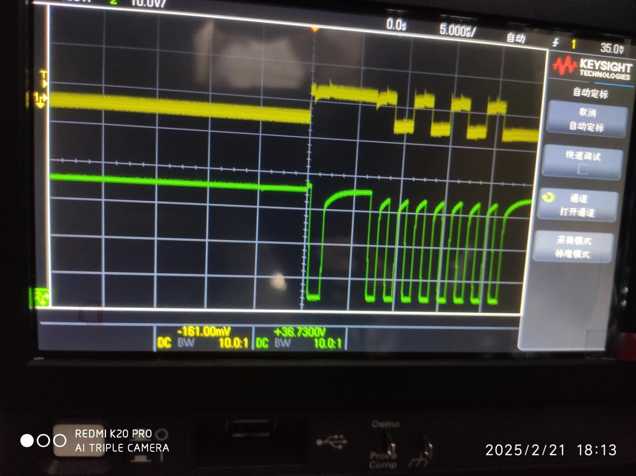
在八位数据前有一个原因不明的时钟上升沿,因此使用模拟SPI:

模拟SPI实现函数:
#define LPSPI0_BUFFER_NUM 2

uint8_t lpspi0_tx_buffer[LPSPI0_BUFFER_NUM] = {0xaa , 0xab};

uint8_t lpspi0_rx_buffer[LPSPI0_BUFFER_NUM] = {0};


#define SPITFTLCD24_RESET_HIGH Siul2_Dio_Ip_WritePin(FAKE_RST_PORT , FAKE_RST_PIN , 1);

#define SPITFTLCD24_RESET_LOW Siul2_Dio_Ip_WritePin(FAKE_RST_PORT , FAKE_RST_PIN , 0);


#define SPITFTLCD24_A0_HIGH Siul2_Dio_Ip_WritePin(FAKE_A0_PORT , FAKE_A0_PIN , 1);

#define SPITFTLCD24_A0_LOW Siul2_Dio_Ip_WritePin(FAKE_A0_PORT , FAKE_A0_PIN , 0);


#define SPITFTLCD24_CS_HIGH Siul2_Dio_Ip_WritePin(FAKE_SPI_CS_PORT , FAKE_SPI_CS_PIN , 1);

#define SPITFTLCD24_CS_LOW Siul2_Dio_Ip_WritePin(FAKE_SPI_CS_PORT , FAKE_SPI_CS_PIN , 0);


#define SPITFTLCD24_MOSI_HIGH Siul2_Dio_Ip_WritePin(FAKE_SPI_MOSI_PORT , FAKE_SPI_MOSI_PIN , 1);

#define SPITFTLCD24_MOSI_LOW Siul2_Dio_Ip_WritePin(FAKE_SPI_MOSI_PORT , FAKE_SPI_MOSI_PIN , 0);


#define SPITFTLCD24_CLK_HIGH Siul2_Dio_Ip_WritePin(FAKE_SPI_CLK_PORT , FAKE_SPI_CLK_PIN , 1);

#define SPITFTLCD24_CLK_LOW Siul2_Dio_Ip_WritePin(FAKE_SPI_CLK_PORT , FAKE_SPI_CLK_PIN , 0);


#define SPITFTLCD24_COLUMN_NUMBER 240

#define SPITFTLCD24_LINE_NUMBER 320

#define SPITFTLCD24_COLUMN_OFFSET 0


#define RED 0xf800

#define GREEN 0x07e0

#define BLUE 0x001f

#define CYAN 0x07ff

#define WHITE 0xffff

#define BLACK 0


void SPITFTLCD24_SEND_CMD(unsigned char o_command)

{

uint8_t i;

SPITFTLCD24_A0_LOW;

SPITFTLCD24_CS_LOW;


SPITFTLCD24_CLK_HIGH;


for(i = 0; i < 8; i ++)

{

SPITFTLCD24_CLK_LOW;


if(o_command & 0x80)

{

SPITFTLCD24_MOSI_HIGH;

}

else

{

SPITFTLCD24_MOSI_LOW;

}


o_command <<= 1;


SPITFTLCD24_CLK_HIGH;


}


SPITFTLCD24_CLK_HIGH;

SPITFTLCD24_CS_HIGH;

}


void SPITFTLCD24_SEND_DATA(unsigned char o_data)

{

uint8_t i;

SPITFTLCD24_A0_HIGH;

SPITFTLCD24_CS_LOW;


for(i = 0; i < 8; i ++)

{

SPITFTLCD24_CLK_LOW;


if(o_data & 0x80)

{

SPITFTLCD24_MOSI_HIGH;

}

else

{

SPITFTLCD24_MOSI_LOW;

}


o_data <<= 1;


SPITFTLCD24_CLK_HIGH;

}


SPITFTLCD24_CS_HIGH;

}


//void SPITFTLCD24_SEND_CMD(unsigned char o_command)

//{

// SPITFTLCD24_A0_LOW;

// SPITFTLCD24_CS_LOW;

// Lpspi_Ip_SyncTransmit(

// //&Lpspi_Ip_PhyUnitConfig_SpiPhyUnit_0_Instance_0

// //错误用法

//

// &Lpspi_Ip_DeviceAttributes_SpiExternalDevice_LPSPI2_Instance_0 ,

// //正确用法

//

// &o_command ,

// NULL ,

// 1 ,

// 0xffff

// );

// SPITFTLCD24_CS_HIGH;

//}

//

//void SPITFTLCD24_SEND_DATA(unsigned char o_data)

//{

// SPITFTLCD24_A0_HIGH;

// SPITFTLCD24_CS_LOW;

// Lpspi_Ip_SyncTransmit(

// &Lpspi_Ip_DeviceAttributes_SpiExternalDevice_LPSPI2_Instance_0 ,

// &o_data ,

// NULL ,

// 1 ,

// 0xffff

// );

// SPITFTLCD24_CS_HIGH;

//}


void SPITFTLCD24_Clear(void)

{

uint32_t row , column;

SPITFTLCD24_SEND_CMD(0x2a); //Column address set

SPITFTLCD24_SEND_DATA(0x00); //start column

SPITFTLCD24_SEND_DATA(0x00);

SPITFTLCD24_SEND_DATA(0x00); //end column

SPITFTLCD24_SEND_DATA(0xF0);


SPITFTLCD24_SEND_CMD(0x2b); //Row address set

SPITFTLCD24_SEND_DATA(0x00); //start row

SPITFTLCD24_SEND_DATA(0x00);

SPITFTLCD24_SEND_DATA(0x01); //end row

SPITFTLCD24_SEND_DATA(0x40);


SPITFTLCD24_SEND_CMD(0x2C); //Memory write

for(row = 0 ; row < SPITFTLCD24_LINE_NUMBER ; row++)

{

for(column = 0 ; column < SPITFTLCD24_COLUMN_NUMBER ; column++)

//column loop

{

SPITFTLCD24_SEND_DATA(0xFF);

SPITFTLCD24_SEND_DATA(0xFF);

}

}

}


void SPITFTLCD24_Full(uint16_t color)

{

uint32_t row , column;


SPITFTLCD24_SEND_CMD(0x2a); //Column address set

SPITFTLCD24_SEND_DATA(0x00); //start column

SPITFTLCD24_SEND_DATA(0x00);

SPITFTLCD24_SEND_DATA(0x00); //end column

SPITFTLCD24_SEND_DATA(0xF0);


SPITFTLCD24_SEND_CMD(0x2b); //Row address set

SPITFTLCD24_SEND_DATA(0x00); //start row

SPITFTLCD24_SEND_DATA(0x00);

SPITFTLCD24_SEND_DATA(0x01); //end row

SPITFTLCD24_SEND_DATA(0x40);


SPITFTLCD24_SEND_CMD(0x2C); //Memory write

for(row = 0 ; row < SPITFTLCD24_LINE_NUMBER ; row++)

{

for(column = 0 ; column < SPITFTLCD24_COLUMN_NUMBER ; column++)

//column loop

{

SPITFTLCD24_SEND_DATA(color >> 8);

SPITFTLCD24_SEND_DATA(color);

}

}

}


void SPITFTLCD24_Init(void)

{


SPITFTLCD24_RESET_LOW;

Pit0_Delay_ms(10);

SPITFTLCD24_RESET_HIGH;

Pit0_Delay_ms(120);


SPITFTLCD24_SEND_CMD(0x01);

//Software Reset

Pit0_Delay_ms(120);


SPITFTLCD24_SEND_CMD(0x11);

//Sleep Out

Pit0_Delay_ms(120);

//DELAY120ms


SPITFTLCD24_SEND_CMD(0x3A); //65k mode

SPITFTLCD24_SEND_DATA(0x05);

SPITFTLCD24_SEND_CMD(0xC5); //VCOM

SPITFTLCD24_SEND_DATA(0x1A);

SPITFTLCD24_SEND_CMD(0x36); // ??L???????????

SPITFTLCD24_SEND_DATA(0x00);

//-------------ST7789V Frame rate setting-----------//

SPITFTLCD24_SEND_CMD(0xb2); //Porch Setting

SPITFTLCD24_SEND_DATA(0x05);

SPITFTLCD24_SEND_DATA(0x05);

SPITFTLCD24_SEND_DATA(0x00);

SPITFTLCD24_SEND_DATA(0x33);

SPITFTLCD24_SEND_DATA(0x33);


SPITFTLCD24_SEND_CMD(0xb7); //Gate Control

SPITFTLCD24_SEND_DATA(0x05); //12.2v -10.43v

//--------------ST7789V Power setting---------------//

SPITFTLCD24_SEND_CMD(0xBB);//VCOM

SPITFTLCD24_SEND_DATA(0x3F);


SPITFTLCD24_SEND_CMD(0xC0); //Power control

SPITFTLCD24_SEND_DATA(0x2c);


SPITFTLCD24_SEND_CMD(0xC2); //VDV and VRH Command Enable

SPITFTLCD24_SEND_DATA(0x01);


SPITFTLCD24_SEND_CMD(0xC3); //VRH Set

SPITFTLCD24_SEND_DATA(0x0F); //4.3+( vcom+vcom offset+vdv)


SPITFTLCD24_SEND_CMD(0xC4); //VDV Set

SPITFTLCD24_SEND_DATA(0x20); //0v


SPITFTLCD24_SEND_CMD(0xC6); //Frame Rate Control in Normal Mode

SPITFTLCD24_SEND_DATA(0X01); //111Hz


SPITFTLCD24_SEND_CMD(0xd0); //Power Control 1

SPITFTLCD24_SEND_DATA(0xa4);

SPITFTLCD24_SEND_DATA(0xa1);


SPITFTLCD24_SEND_CMD(0xE8); //Power Control 1

SPITFTLCD24_SEND_DATA(0x03);


SPITFTLCD24_SEND_CMD(0xE9); //Equalize time control

SPITFTLCD24_SEND_DATA(0x09);

SPITFTLCD24_SEND_DATA(0x09);

SPITFTLCD24_SEND_DATA(0x08);

//---------------ST7789V gamma setting-------------//

SPITFTLCD24_SEND_CMD(0xE0); //Set Gamma

SPITFTLCD24_SEND_DATA(0xD0);

SPITFTLCD24_SEND_DATA(0x05);

SPITFTLCD24_SEND_DATA(0x09);

SPITFTLCD24_SEND_DATA(0x09);

SPITFTLCD24_SEND_DATA(0x08);

SPITFTLCD24_SEND_DATA(0x14);

SPITFTLCD24_SEND_DATA(0x28);

SPITFTLCD24_SEND_DATA(0x33);

SPITFTLCD24_SEND_DATA(0x3F);

SPITFTLCD24_SEND_DATA(0x07);

SPITFTLCD24_SEND_DATA(0x13);

SPITFTLCD24_SEND_DATA(0x14);

SPITFTLCD24_SEND_DATA(0x28);

SPITFTLCD24_SEND_DATA(0x30);


SPITFTLCD24_SEND_CMD(0XE1); //Set Gamma

SPITFTLCD24_SEND_DATA(0xD0);

SPITFTLCD24_SEND_DATA(0x05);

SPITFTLCD24_SEND_DATA(0x09);

SPITFTLCD24_SEND_DATA(0x09);

SPITFTLCD24_SEND_DATA(0x08);

SPITFTLCD24_SEND_DATA(0x03);

SPITFTLCD24_SEND_DATA(0x24);

SPITFTLCD24_SEND_DATA(0x32);

SPITFTLCD24_SEND_DATA(0x32);

SPITFTLCD24_SEND_DATA(0x3B);

SPITFTLCD24_SEND_DATA(0x14);

SPITFTLCD24_SEND_DATA(0x13);

SPITFTLCD24_SEND_DATA(0x28);

SPITFTLCD24_SEND_DATA(0x2F);


SPITFTLCD24_SEND_CMD(0x20);

Pit0_Delay_ms(120);

SPITFTLCD24_SEND_CMD(0x29);

}
但是效果不理想,刷屏太慢,因此还在想别的办法。
2. CAN通信
调试CAN通信这个环节不是很顺利,即使到最后能输出波形,但是仍然不能与其他厂商的MCU成功进行CAN通信。
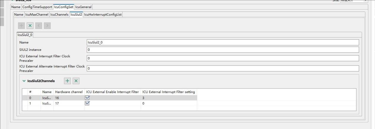
调试CAN通信需要先把前置模块Siul2_Icu模块使能,并添加两个通道:
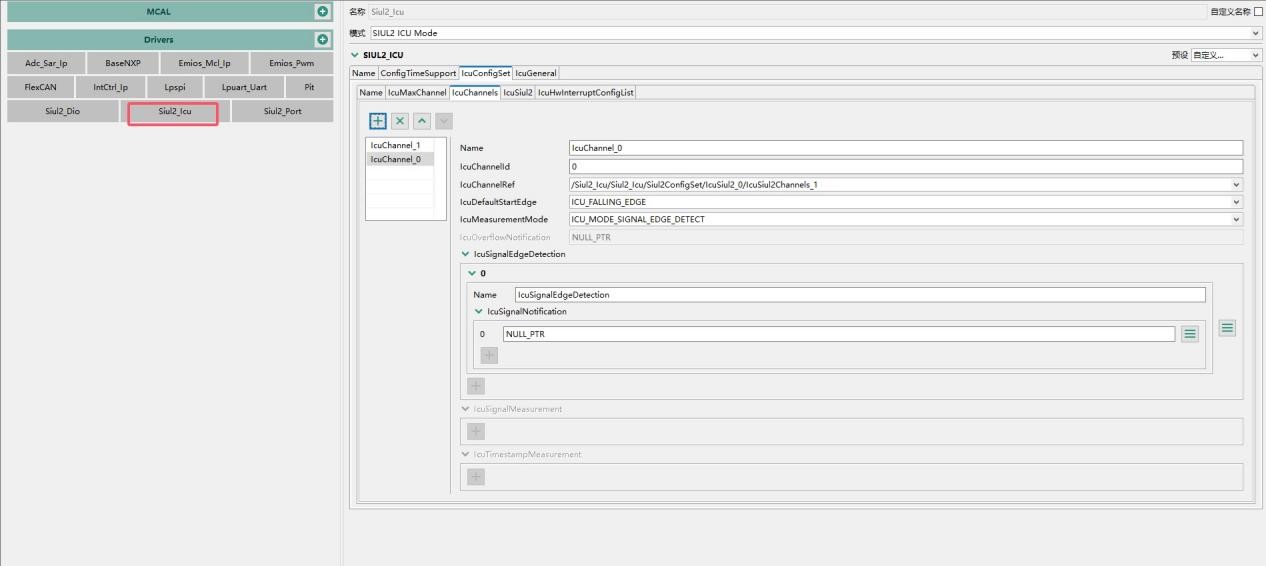
添加硬件通道16和17:
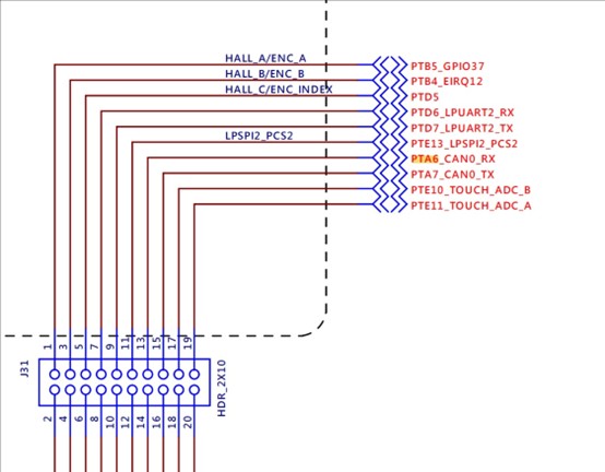
引脚则是选用PTA6和PTA7作为CAN0的输出:

PTA6和PTA7在J31母座上:
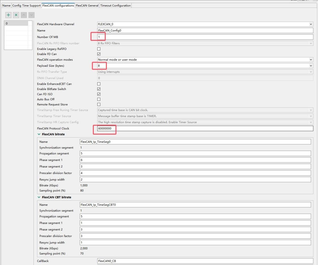
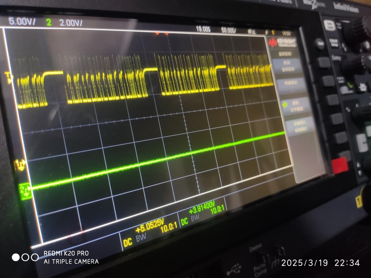
对于FlexCAN的配置则是参考论坛的帖子进行的,自己改了一些参数,设置1MB长度,Payload 8字节,协议时钟和波特率参数则是照抄:
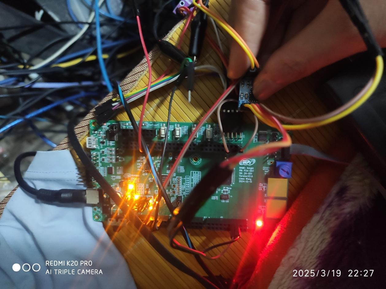
将PTA6和PTA7引脚与CAN收发模块进行连接:
初始化和CAN发送代码如下:
Siul2_Icu_Ip_Init(0,&Siul2_Icu_Ip_0_Config_PB);

Siul2_Icu_Ip_EnableInterrupt(0,(*Siul2_Icu_Ip_0_Config_PB.pChannelsConfig)[0].hwChannel);

Siul2_Icu_Ip_EnableInterrupt(0,(*Siul2_Icu_Ip_0_Config_PB.pChannelsConfig)[1].hwChannel);

Siul2_Icu_Ip_EnableNotification(0,(*Siul2_Icu_Ip_0_Config_PB.pChannelsConfig)[0].hwChannel);

Siul2_Icu_Ip_EnableNotification(0,(*Siul2_Icu_Ip_0_Config_PB.pChannelsConfig)[1].hwChannel);


FlexCAN_Ip_Init(0, &FlexCAN_State0, &FlexCAN_Config0);

FlexCAN_Ip_SetStartMode(0);


while(1)

{

FlexCAN_Ip_Send(0 , TX_MB_IDX , &CAN_NODE_0_TX_MB0_Config , FLEXCAN_MSG_ID , (uint8_t *)&dummyData);

Pit0_Delay_ms(100);

printf("FlexCAN_Ip_Send.\n");

}
将示波器的探头接入CANH和CANL两个输出引脚:
文章来自“S32K312 开发板评测活动”测评者:李明
欢迎在博文下方留言评论,我们会及时回复您的问题。


 231
231

 被折叠的 条评论
为什么被折叠?
被折叠的 条评论
为什么被折叠?
 到【灌水乐园】发言


