


 本文探讨了三相单回路传输系统在电力行业中的重要性,包括其高效传输、系统稳定性、可靠性以及安装维护便利性。同时,文章提供了使用Matlab实现的示例代码,展示了如何计算和模拟这种系统。
💥💥💞💞欢迎来到本博客❤️❤️💥💥
🏆博主优势:🌞🌞🌞博客内容尽量做到思维缜密,逻辑清晰,为了方便读者。
⛳️座右铭:行百里者,半于九十。
📋📋📋本文目录如下:🎁🎁🎁
目录
💥1 概述
基于所有三相的集束导体组成的三相单回路传输系统,是一种广泛应用于电力系统的传输方式。在我国,随着电力行业的快速发展,这种传输系统在电力输送、配电以及新能源接入等方面发挥着越来越重要的作用。
三相单回路传输系统主要由三相电源、集束导体和传输线路组成。其中,集束导体是由三根相互绝缘的导线组成,它们按照一定的间距排列在一起,形成了稳定的传输通道。这种传输系统具有以下几个优点:
1.高效传输:三相单回路传输系统能够实现电能的高效传输,降低输电损耗。相较于单相传输,三相传输具有更高的传输效率,能够在相同的输电容量下减少输电线路的尺寸和重量。
2.系统稳定性:集束导体的结构设计使得三相单回路传输系统具有较好的抗干扰能力和系统稳定性。在传输过程中,三相电流相互平衡,降低了电磁干扰和电压不平衡等问题。
3.可靠性高:集束导体采用绝缘材料进行封装,具有良好的绝缘性能和抗老化性能,提高了整个传输系统的可靠性。同时,传输线路采用金属导体,具有较高的导电性能和抗拉伸性能,进一步保证了系统的稳定运行。
4.安装维护方便:三相单回路传输系统采用模块化设计,安装和维护起来十分方便。集束导体结构紧凑,占地面积小,有利于节约土地资源。同时,传输线路的维护周期长,降低了运行成本。
5.适应性强:基于所有三相的集束导体组成的三相单回路传输系统,能够适应各种复杂的地理环境和气候条件。在我国,这种传输系统已经成功应用于高原、山区、沿海等地区,取得了良好的运行效果。
然而,在实际应用中,我们也需要关注三相单回路传输系统的一些潜在问题,如线路老化、绝缘损坏、电压不平衡等。为了确保系统的安全稳定运行,我们需要定期对传输系统进行检查和维护,及时发现并排除隐患。
综上所述,基于所有三相的集束导体组成的三相单回路传输系统在我国电力系统中具有广泛的应用前景。在今后的发展中,我们应当继续优化这种传输系统的设计和运行管理,提高其安全稳定性,以满足不断增长的电力需求。同时,也要关注新型传输技术的研发和应用。
📚2 运行结果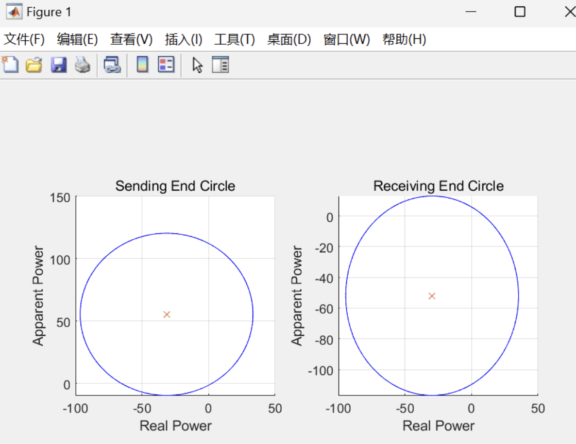
主函数部分代码:
clear;
clc;
%% TnD Group Task
% Members:
% 107120001 - Aayush
% 107120003 - Abhishek
% 107120037 - Dhruva
%% Inputs
system = input('Type of the system Symmetrical(Put 1) Unsymmetrical Spacing(Put 2): ');
if system == 1
Symmetrical_Spacing = input('Spacing between the phase conductors(m)(Symmetrical): ');
else
Phase_Distance1 = input('Spacing between the phase conductors(enter distance)(m) a(Unsymmetrical): ');
Phase_Distance2 = input('Spacing between the phase conductors(enter distance)(m) b(Unsymmetrical): ');
Phase_Distance3 = input('Spacing between the phase conductors(enter distance)(m) c(Unsymmetrical): ');
end
No_of_Sub_Conductors = input('Number of sub-conductors per bundle: ');
Sub_Conductor_Spacing = input('Spacing between the sub-conductors(m): ');
No_of_Strands = input('Number of strands in each sub-conductor: ');
diameter_of_strand = input('Diameter of each strand(m): ');
Length_of_Line= input('Length of line(km): ');
Transmission_Model = input('Transmission_Model of Line(1-Short , 2-Nominal Pi ,3-Long): ');
resistance = input('Resistance of line per km(Ohms): ');
Frequency = input('Power Frequency(Hz): ');
Nominal_Voltage = input('Nominal Voltage(V): ');
Receiving_End_Power = input('Receiving end load(MW): ');
power_factor = input('Power factor of receiving end load: ');
%% Computations
% Receiving end voltage is maintained at nominal system voltage
VR = Nominal_Voltage / sqrt(3);
% Calculating Radius r
% 3(No_of_layers)^2 - 3(No_of_layers) + 1- (No_of_strands) = 0
% p(n)^2 + qn + r = 0
p = 3;
q = -3;
r = 1 - No_of_Strands;
% Calculating the Discriminant
di = (q * q) - (4 * p * r);
% Finding two solutions
sol1 = (-q - sqrt(di)) / (2 * p);
sol2 = (-q + sqrt(di)) / (2 * p);
Real_part1 = sum(real(sol1(:)));
Real_part2 = sum(real(sol2(:)));
if Real_part1 >= Real_part2
n = Real_part1;
else
n = Real_part2;
end
D = (2 * n - 1) * diameter_of_strand;
r = D / 2;
% Inductance(L)
if system == 1
MGMD = Symmetrical_Spacing;
if No_of_Sub_Conductors == 2
SGMD = (r * 0.7788 * Sub_Conductor_Spacing)^(1/No_of_Sub_Conductors);
elseif No_of_Sub_Conductors == 3
SGMD = (r * Sub_Conductor_Spacing^(2) * 0.7788)^(1/No_of_Sub_Conductors);
elseif No_of_Sub_Conductors == 4
SGMD = (r * Sub_Conductor_Spacing^(3) * 0.7788 * sqrt(2))^(1/No_of_Sub_Conductors);
elseif No_of_Sub_Conductors == 5
SGMD = (r * Sub_Conductor_Spacing^(4) * 0.7788 * (1.618)^2)^(1/No_of_Sub_Conductors);
elseif No_of_Sub_Conductors == 6
SGMD = (r * Sub_Conductor_Spacing^(5) * 0.7788 * 6)^(1/No_of_Sub_Conductors);
elseif No_of_Sub_Conductors == 7
SGMD = (r * Sub_Conductor_Spacing^(6) * 0.7788 * 16.39)^(1/No_of_Sub_Conductors);
else
fprintf("\n\nValue of No_of_Sub_Conductors above 7 is not practically feasible so its value can't be %d ", No_of_Sub_Conductors);
end
else
MGMD = (Phase_Distance1 *Phase_Distance2 *Phase_Distance3)^(1 / 3);
if No_of_Sub_Conductors == 2
SGMD = exp(-1 / (4*No_of_Sub_Conductors)) * (r^(1 / No_of_Sub_Conductors)) * Sub_Conductor_Spacing^(1 / No_of_Sub_Conductors);
elseif No_of_Sub_Conductors == 3
SGMD = (r * (Sub_Conductor_Spacing)^(2) * 0.7788)^(1 / No_of_Sub_Conductors);
elseif No_of_Sub_Conductors == 4
SGMD = (sqrt(2) * r * (Sub_Conductor_Spacing)^(3) * 0.7788)^(1 / No_of_Sub_Conductors);
elseif No_of_Sub_Conductors == 5
SGMD = (r * Sub_Conductor_Spacing^(4) * 0.7788 * (1.618)^2)^(1/No_of_Sub_Conductors);
elseif No_of_Sub_Conductors == 6
SGMD = (r * Sub_Conductor_Spacing^(5) * 0.7788 * 6)^(1/No_of_Sub_Conductors);
elseif No_of_Sub_Conductors == 7
SGMD = (r * Sub_Conductor_Spacing^(6) * 0.7788 * 16.39)^(1/No_of_Sub_Conductors);
else
fprintf("Value of No_of_Sub_Conductors above 7 is not practically feasible so its value can't be %d ", No_of_Sub_Conductors);
end
end
🎉3 参考文献
[1]王建民.平行集束电缆的制造及新型模具设计[J].电线电缆,2004,(06):21-23.
部分理论引用网络文献,若有侵权联系博主删除。


 879
879

 被折叠的 条评论
为什么被折叠?
被折叠的 条评论
为什么被折叠?
 到【灌水乐园】发言


