


FPGA教程系列-计数器和分频器的仿真(非IP核)
计数
计数是一种最简单基本的运算,简单的理解就是一个时钟沿进行加一的一个操作。溢出以后重新归零开始。
分频
分频器顾名思义就是对输入时钟进行分频,得到所需要的时钟。在F PGA 的设计中,由于板卡的晶振一般是固定的,而对于一些工程而言晶振时钟并不是都能满足设计需求,所以在项目设计中经常使用分频器对输入时钟进行分频。
实现分频一般有两种方法,一种方法是直接使用PLL 进行分频,比如在FPGA 或者ASIC 设计中,都可以直接使用PLL 进行分频。但是这种分频有时候受限于PLL 本身的特性,比如输入100Mhz 时钟,很多PLL 都实现不了1Mhz 的时钟分频,这个就是PLL 本身特性限制的。另外一种方法是直接使用代码来实现分频。根据分频器的分频比例(分频前的频率和分频后的频率比值)是偶数还是奇数,将分频器分为偶数分频器和奇数分频器。
偶数分频器比较简单,时序如下图所示:
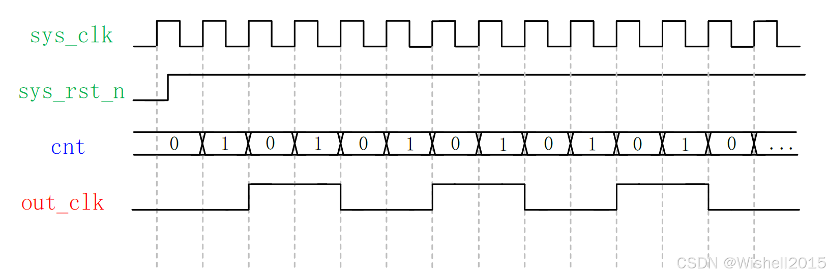
奇数分频器相对偶数分频来说比较复杂, 需要知道的可以自己去查,这里只是针对于偶数分频来做一个仿真, 在具体的项目中,大多数使用的都是PLL来实现时钟的分频,因此这部分仅仅是作为一个了解。
Top编写
//==============================================================================
// Module: counter_and_clock_divider
// Date: 2025-11-07
//
// Description:
// This module implements a configurable counter and derives several
// clock-divided signals from the counter's lower bits.
// - The counter counts from 0 to COUNTER_MAX and then wraps around.
// - The divided clocks are generated by tapping into the counter's bits.
//   o_clk2div has a period of 2 * i_clk period.
//   o_clk4div has a period of 4 * i_clk period, and so on.
//==============================================================================

module counter_and_clock_divider #(
    // --- Parameters ---
    parameter COUNTER_MAX = 99,       // The maximum value before the counter wraps (e.g., 99 for a 0-99 count)
    parameter COUNTER_WIDTH = 10      // The width of the counter output register
) (
    // --- Inputs ---
    input  wire i_clk,                // Main clock input
    input  wire i_rst,                // Asynchronous reset, active high

    // --- Outputs ---
    output reg  signed [COUNTER_WIDTH-1:0] o_cout, // The current counter value
    output wire o_clk2div,            // Clock divided by 2
    output wire o_clk4div,            // Clock divided by 4
    output wire o_clk8div,            // Clock divided by 8
    output wire o_clk16div            // Clock divided by 16
);

    //==========================================================================
    // Counter Logic
    // Description: A simple up-counter with asynchronous reset.
    //==========================================================================
    always @(posedge i_clk or posedge i_rst) begin
        if (i_rst) begin
            // On reset, set the counter to 0
            o_cout <= {COUNTER_WIDTH{1'b0}};
        end else begin
            // If the counter has reached its maximum value, wrap around to 0
            if (o_cout == COUNTER_MAX) begin
                o_cout <= {COUNTER_WIDTH{1'b0}};
            end else begin
                // Otherwise, increment the counter
                o_cout <= o_cout + 1'b1;
            end
        end
    end

    //==========================================================================
    // Clock Divider Logic
    // Description: Derive divided clocks from the counter's lower bits.
    // This is a common and efficient way to generate clock enables or
    // slower clocks from a faster master clock.
    //==========================================================================
    assign o_clk2div  = o_cout[0];
    assign o_clk4div  = o_cout[1];
    assign o_clk8div  = o_cout[2];
    assign o_clk16div = o_cout[3];

endmodule
Testbench编写
//==============================================================================
// Module: tb_counter_and_clock_divider
// Date: 2025-11-07
//
// Description:
// Testbench for the 'counter_and_clock_divider' module.
// It demonstrates the counting and clock division functionality by
// running the simulation and printing the status of all signals.
//==============================================================================

`timescale 1ns / 1ps

module tb_counter_and_clock_divider;

    //==========================================================================
    // Parameters (must match the DUT's parameters)
    //==========================================================================
    localparam COUNTER_MAX = 99;
    localparam COUNTER_WIDTH = 10;
    localparam CLK_PERIOD = 10; // 10ns -> 100MHz

    //==========================================================================
    // Testbench Signals
    //==========================================================================
    reg                         tb_i_clk;
    reg                         tb_i_rst;
    wire signed [COUNTER_WIDTH-1:0] tb_o_cout;
    wire                        tb_o_clk2div;
    wire                        tb_o_clk4div;
    wire                        tb_o_clk8div;
    wire                        tb_o_clk16div;

    //==========================================================================
    // DUT (Design Under Test) Instantiation
    //==========================================================================
    counter_and_clock_divider #(
        .COUNTER_MAX   (COUNTER_MAX),
        .COUNTER_WIDTH (COUNTER_WIDTH)
    ) DUT (
        .i_clk    (tb_i_clk),
        .i_rst    (tb_i_rst),
        .o_cout   (tb_o_cout),
        .o_clk2div (tb_o_clk2div),
        .o_clk4div (tb_o_clk4div),
        .o_clk8div (tb_o_clk8div),
        .o_clk16div(tb_o_clk16div)
    );

    //==========================================================================
    // Clock Generation
    //==========================================================================
    initial begin
        tb_i_clk = 0;
        forever #(CLK_PERIOD / 2) tb_i_clk = ~tb_i_clk;
    end

    //==========================================================================
    // Test Sequence and Monitoring
    //==========================================================================
    initial begin
        // 1. Initialize Inputs
        tb_i_rst = 1'b1;

        // 2. Start Monitoring and Apply Reset
        $display("--- Test Started at time %0t ---", $time);
        $monitor("Time=%0t ns | clk=%b, rst=%b | count=%0d | clk2=%b, clk4=%b, clk8=%b, clk16=%b",
                 $time, tb_i_clk, tb_i_rst, tb_o_cout, tb_o_clk2div, tb_o_clk4div, tb_o_clk8div, tb_o_clk16div);

        // Hold reset for a few cycles
        #(CLK_PERIOD * 2);
        $display("\n[%0t] Releasing reset...", $time);
        tb_i_rst = 1'b0;

        // 3. Let the DUT run to demonstrate functionality
        // We will run for 300 clock cycles to see 3 full count cycles (0-99).
        $display("\n--- Running for 300 clock cycles to observe counting and division ---");
        #(CLK_PERIOD * 300);

        // 4. End of Test
        $display("\n--- Test Finished at time %0t ---", $time);
        $finish;
    end

endmodule
仿真
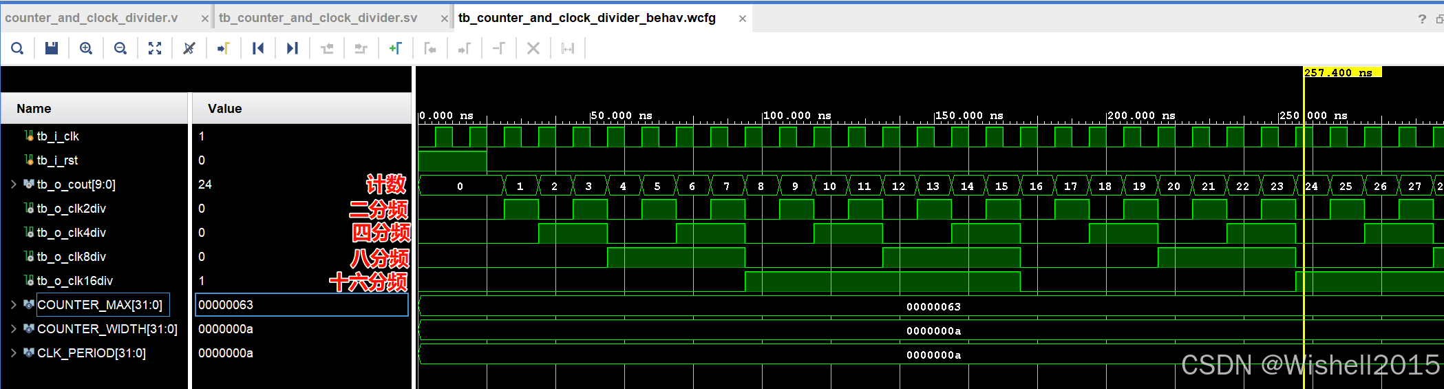
结果非常直观,没有什么需要太多的解释的。


 2391
2391

 被折叠的 条评论
为什么被折叠?
被折叠的 条评论
为什么被折叠?
 到【灌水乐园】发言


