


一、在 Rviz 中显示一个盒状模型
1.1 新建文件夹catkin_ws01,输入以下命令
mkdir catkin_ws01
cd catkin_ws01/
mkdir src
cd src/
catkin_init_workspace
在src目录下输入以下命令:
catkin_create_pkg jubot_demo urdf xacro #创建功能包、添加依赖
cd jubot_demo/
mkdir urdf
mkdir launch
mkdir meshes #存放渲染机器人模型的文件
mkdir config #存放rviz配置的文件
urdf文件夹中添加一个box_urdf.urdf文件,输入代码如下
<robot name="mycar">
    <link name="base_link">
        <visual>
            <geometry>
                <box size="0.5 0.2 0.1" />
            </geometry>
        </visual>
    </link>
</robot>
1.2 在 launch 文件中集成 URDF 与 Rviz
在launch目录下,新建一个 box_launch.launch 文件
<launch>

    <!-- 设置参数 -->
    <param name="robot_description" textfile="$(find jubot_demo)/urdf/box_urdf.urdf" />

    <!-- 启动 rviz -->
    <node pkg="rviz" type="rviz" name="rviz" />

</launch>
1.3 在 Rviz 中显示模型
在这个文件夹下打开终端输入命令,启动launch文件
catkin_make
catkin_make install
source devel/setup.bash
echo $ROS_PACKAGE_PATH
roslaunch src/jubot_demo/launch/box_launch.launch
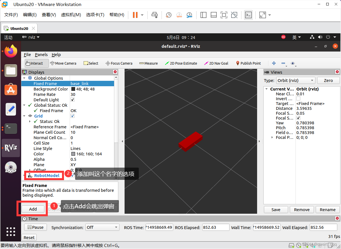
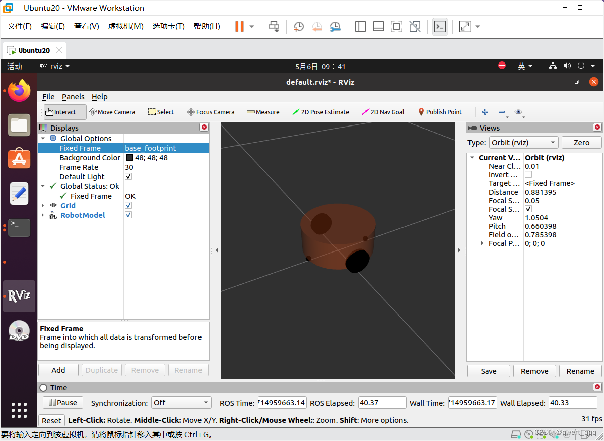
rviz 启动后,会发现并没有盒装的机器人模型,这是因为默认情况下没有添加机器人显示组件,需要手动添加,添加方式如下
如果没有颜色,或者报错no TF data
可以重新打开一个终端窗口输入
rosrun tf static_transform_publisher 0 0 0 0 0 0 1 map base_link 5
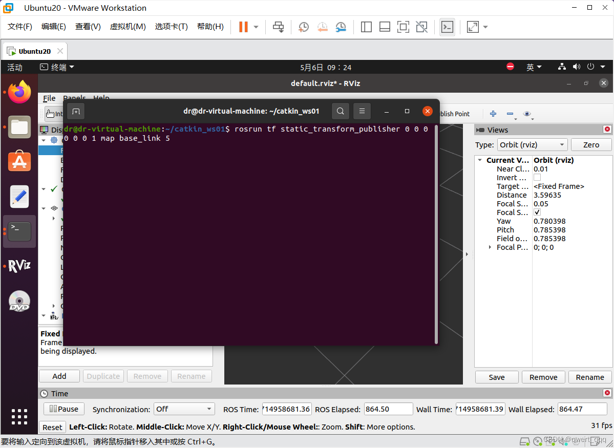
然后就可以看到Fixed Frame可以切换为base_link了,如果有其他显示异常可以对比左边那一栏是不是有显示橙色或者红色的报错信息,一般解决完就会显示正常了。
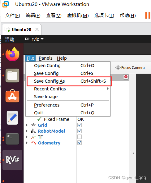
1.4 优化 rviz 启动
首先,将当前配置保存进config目录
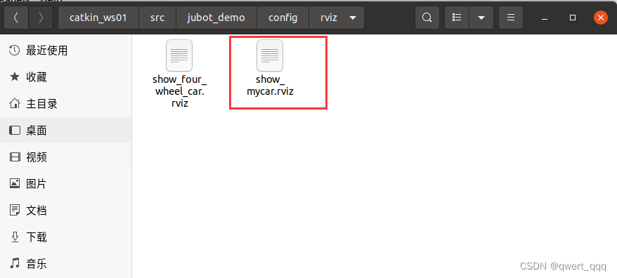
然后,修改launch文件中 Rviz 的启动配置添加参数:args,值设置为-d 配置文件路径
<launch>
	<!--设置参数-->
	<param name=" robot_description" textfile="$(find jubot_demo)/urdf/box_urdf. urdf"/>
	<! --启动rviz -->
	<node pkg=" rviz" type=" rviz" name= " rviz"/>

    <param name="robot_description" textfile="$(find jubot_demo)/urdf/box_urdf.urdf" />
    <node pkg="rviz" type="rviz" name="rviz" args="-d $(find jubot_demo)/config/rviz/show_mycar.rviz" />
</launch>
再启动时,就可以包含之前的组件配置了,使用更方便快捷。
二、创建一个四轮圆柱状机器人模型
2.1 配置urdf和launch文件
在已有的urdf和launch文件基础上进行修改
box_urdf.urdf
<!-- <robot name="mycar">
    <link name="base_link">
        <visual>
            <geometry>
                <box size="0.5 0.2 0.1" />
            </geometry>
        </visual>
    </link>
</robot> -->


<robot name="mycar">
  <!-- 设置 base_footprint  -->
  <link name="base_footprint">
    <visual>
      <geometry>
        <sphere radius="0.001" />
      </geometry>
    </visual>
  </link>

  <!-- 添加底盘 -->
  <!--
        参数
            形状:圆柱
            半径:10     cm
            高度:8      cm
            离地:1.5    cm

    -->
  <link name="base_link">
    <visual>
      <geometry>
        <cylinder radius="0.1" length="0.08" />
      </geometry>
      <origin xyz="0 0 0" rpy="0 0 0" />
      <material name="yellow">
        <color rgba="0.8 0.3 0.1 0.5" />
      </material>
    </visual>
  </link>

  <joint name="base_link2base_footprint" type="fixed">
    <parent link="base_footprint" />
    <child link="base_link"/>
    <origin xyz="0 0 0.055" />
  </joint>

  <!-- 添加驱动轮 -->
  <!-- 添加驱动轮 -->
  <!--
        驱动轮是侧翻的圆柱
        参数
            半径: 3.25 cm
            宽度: 1.5  cm
            颜色: 黑色
        关节设置:
            x = 0
            y = 底盘的半径 + 轮胎宽度 / 2
            z = 离地间距 + 底盘长度 / 2 - 轮胎半径 = 1.5 + 4 - 3.25 = 2.25(cm)
            axis = 0 1 0
    -->
  <link name="left_wheel">
    <visual>
      <geometry>
        <cylinder radius="0.0325" length="0.015" />
      </geometry>
      <origin xyz="0 0 0" rpy="1.5705 0 0" />
      <material name="black">
        <color rgba="0.0 0.0 0.0 1.0" />
      </material>
    </visual>

  </link>

  <joint name="left_wheel2base_link" type="continuous">
    <parent link="base_link" />
    <child link="left_wheel" />
    <origin xyz="0 0.1 -0.0225" />
    <axis xyz="0 1 0" />
  </joint>


  <link name="right_wheel">
    <visual>
      <geometry>
        <cylinder radius="0.0325" length="0.015" />
      </geometry>
      <origin xyz="0 0 0" rpy="1.5705 0 0" />
      <material name="black">
        <color rgba="0.0 0.0 0.0 1.0" />
      </material>
    </visual>

  </link>

  <joint name="right_wheel2base_link" type="continuous">
    <parent link="base_link" />
    <child link="right_wheel" />
    <origin xyz="0 -0.1 -0.0225" />
    <axis xyz="0 1 0" />

  </joint>


  <!-- 添加万向轮(支撑轮) -->
  <!-- 添加万向轮(支撑轮) -->
  <!--
        参数
            形状: 球体
            半径: 0.75 cm
            颜色: 黑色

        关节设置:
            x = 自定义(底盘半径 - 万向轮半径) = 0.1 - 0.0075 = 0.0925(cm)
            y = 0
            z = 底盘长度 / 2 + 离地间距 / 2 = 0.08 / 2 + 0.015 / 2 = 0.0475 axis= 1 1 1

    -->
  <link name="front_wheel">
    <visual>
      <geometry>
        <sphere radius="0.0075" />
      </geometry>
      <origin xyz="0 0 0" rpy="0 0 0" />
      <material name="black">
        <color rgba="0.0 0.0 0.0 1.0" />
      </material>
    </visual>
  </link>

  <joint name="front_wheel2base_link" type="continuous">
    <parent link="base_link" />
    <child link="front_wheel" />
    <origin xyz="0.0925 0 -0.0475" />
    <axis xyz="1 1 1" />
  </joint>

  <link name="back_wheel">
    <visual>
      <geometry>
        <sphere radius="0.0075" />
      </geometry>
      <origin xyz="0 0 0" rpy="0 0 0" />
      <material name="black">
        <color rgba="0.0 0.0 0.0 1.0" />
      </material>
    </visual>
  </link>

  <joint name="back_wheel2base_link" type="continuous">
    <parent link="base_link" />
    <child link="back_wheel" />
    <origin xyz="-0.0925 0 -0.0475" />
    <axis xyz="1 1 1" />
  </joint>
</robot>
box_launch.launch文件
<launch>

  <!-- 将 urdf 文件内容设置进参数服务器 -->
  <param name="robot_description" textfile="$(find jubot_demo)/urdf/box_urdf.urdf" />

  <!-- 启动 rviz -->
  <!-- <node pkg="rviz" type="rviz" name="rviz" /> -->
  <node pkg="rviz" type="rviz" name="rviz" args="-d $(find jubot_demo)/config/rviz/show_four_wheel_car.rviz" />

  <!-- 启动机器人状态和关节状态发布节点 -->
  <node pkg="robot_state_publisher" type="robot_state_publisher" name="robot_state_publisher" />
  <node pkg="joint_state_publisher" type="joint_state_publisher" name="joint_state_publisher" />

  <!-- 启动图形化的控制关节运动节点 -->
  <node pkg="joint_state_publisher_gui" type="joint_state_publisher_gui" name="joint_state_publisher_gui" />


</launch>
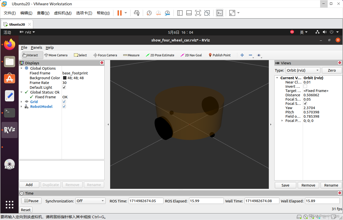
然后启动roslaunch,在rviz中显示机器人模型:
catkin_make
catkin_make install
source devel/setup.bash
echo $ROS_PACKAGE_PATH
roslaunch src/jubot_demo/launch/box_launch.launch
2.2 URDF优化_xacro
- 在设计关节的位置时,需要按照一定的公式计算,公式是固定的,但是在 URDF 中依赖于人工计算,存在不便,容易计算失误,且当某些参数发生改变时,还需要重新计算。
- URDF 中的部分内容是高度重复的,驱动轮与支撑轮的设计实现,不同轮子只是部分参数不同,形状、颜色、翻转量都是一致的,在实际应用中,构建复杂的机器人模型时,更是易于出现高度重复的设计,按照一般的编程涉及到重复代码应该考虑封装。
在编程语言中,可以通过变量结合函数直接解决上述问题,在 ROS 中,已经给出了类似编程的优化方案,称之为:Xacro,较之于纯粹的 URDF 实现,可以编写更安全、精简、易读性更强的机器人模型文件,且可以提高编写效率。
2.2.1 配置xacro文件
在urdf文件夹下新建一个xacro文件夹,在文件夹中新建my_base.urdf.xacro文件
<!--
    使用 xacro 优化 URDF 版的小车底盘实现:

    实现思路:
    1.将一些常量、变量封装为 xacro:property
      比如:PI 值、小车底盘半径、离地间距、车轮半径、宽度 ....
    2.使用 宏 封装驱动轮以及支撑轮实现,调用相关宏生成驱动轮与支撑轮

-->
<!-- 根标签,必须声明 xmlns:xacro -->
<robot name="my_base" xmlns:xacro="http://www.ros.org/wiki/xacro">
    <!-- 封装变量、常量 -->
    <xacro:property name="PI" value="3.141"/>
    <!-- 宏:黑色设置 -->
    <material name="black">
        <color rgba="0.0 0.0 0.0 1.0" />
    </material>
    <!-- 底盘属性 -->
    <xacro:property name="base_footprint_radius" value="0.001" /> <!-- base_footprint 半径  -->
    <xacro:property name="base_link_radius" value="0.1" /> <!-- base_link 半径 -->
    <xacro:property name="base_link_length" value="0.08" /> <!-- base_link 长 -->
    <xacro:property name="earth_space" value="0.015" /> <!-- 离地间距 -->

    <!-- 底盘 -->
    <link name="base_footprint">
      <visual>
        <geometry>
          <sphere radius="${base_footprint_radius}" />
        </geometry>
      </visual>
    </link>

    <link name="base_link">
      <visual>
        <geometry>
          <cylinder radius="${base_link_radius}" length="${base_link_length}" />
        </geometry>
        <origin xyz="0 0 0" rpy="0 0 0" />
        <material name="yellow">
          <color rgba="0.5 0.3 0.0 0.5" />
        </material>
      </visual>
    </link>

    <joint name="base_link2base_footprint" type="fixed">
      <parent link="base_footprint" />
      <child link="base_link" />
      <origin xyz="0 0 ${earth_space + base_link_length / 2 }" />
    </joint>

    <!-- 驱动轮 -->
    <!-- 驱动轮属性 -->
    <xacro:property name="wheel_radius" value="0.0325" /><!-- 半径 -->
    <xacro:property name="wheel_length" value="0.015" /><!-- 宽度 -->
    <!-- 驱动轮宏实现 -->
    <xacro:macro name="add_wheels" params="name flag">
      <link name="${name}_wheel">
        <visual>
          <geometry>
            <cylinder radius="${wheel_radius}" length="${wheel_length}" />
          </geometry>
          <origin xyz="0.0 0.0 0.0" rpy="${PI / 2} 0.0 0.0" />
          <material name="black" />
        </visual>
      </link>

      <joint name="${name}_wheel2base_link" type="continuous">
        <parent link="base_link" />
        <child link="${name}_wheel" />
        <origin xyz="0 ${flag * base_link_radius} ${-(earth_space + base_link_length / 2 - wheel_radius) }" />
        <axis xyz="0 1 0" />
      </joint>
    </xacro:macro>
    <xacro:add_wheels name="left" flag="1" />
    <xacro:add_wheels name="right" flag="-1" />
    <!-- 支撑轮 -->
    <!-- 支撑轮属性 -->
    <xacro:property name="support_wheel_radius" value="0.0075" /> <!-- 支撑轮半径 -->

    <!-- 支撑轮宏 -->
    <xacro:macro name="add_support_wheel" params="name flag" >
      <link name="${name}_wheel">
        <visual>
            <geometry>
                <sphere radius="${support_wheel_radius}" />
            </geometry>
            <origin xyz="0 0 0" rpy="0 0 0" />
            <material name="black" />
        </visual>
      </link>

      <joint name="${name}_wheel2base_link" type="continuous">
          <parent link="base_link" />
          <child link="${name}_wheel" />
          <origin xyz="${flag * (base_link_radius - support_wheel_radius)} 0 ${-(base_link_length / 2 + earth_space / 2)}" />
          <axis xyz="1 1 1" />
      </joint>
    </xacro:macro>

    <xacro:add_support_wheel name="front" flag="1" />
    <xacro:add_support_wheel name="back" flag="-1" />

</robot>
2.2.2 集成launch文件
box_launch.launch
<launch>

  <!-- 将 urdf 文件内容设置进参数服务器 -->
  <!-- <param name="robot_description" textfile="$(find jubot_demo)/urdf/box_urdf.urdf" /> -->

  <!-- 使用xacro优化urdf文件 -->
  <param name="robot_description" command="$(find xacro)/xacro $(find jubot_demo)/urdf/xacro/my_base.urdf.xacro" />

  <!-- 启动 rviz -->
  <!-- <node pkg="rviz" type="rviz" name="rviz" /> -->
  <node pkg="rviz" type="rviz" name="rviz" args="-d $(find jubot_demo)/config/rviz/show_four_wheel_car.rviz" />

  <!-- 启动机器人状态和关节状态发布节点 -->
  <node pkg="robot_state_publisher" type="robot_state_publisher" name="robot_state_publisher" />
  <node pkg="joint_state_publisher" type="joint_state_publisher" name="joint_state_publisher" />

  <!-- 启动图形化的控制关节运动节点 -->
  <node pkg="joint_state_publisher_gui" type="joint_state_publisher_gui" name="joint_state_publisher_gui" />


</launch>
加载robot_description时使用command属性,属性值就是调用 xacro 功能包的 xacro 程序直接解析 xacro 文件。
重新启动launch,正常显示小车,说明配置成功
2.3 添加摄像头和雷达传感器
2.3.1 摄像头和雷达 Xacro 文件实现
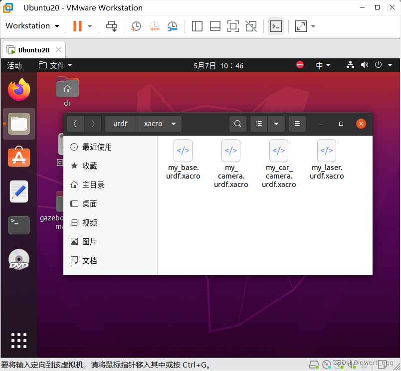
创建
my_camera.urdf.xacro
my_laser.urdf.xacro
my_car_camera.urdf.xacro
三个文件
摄像头my_camera.urdf.xacro 文件:
<!-- 摄像头相关的 xacro 文件 -->
<robot name="my_camera" xmlns:xacro="http://wiki.ros.org/xacro">
    <!-- 摄像头属性 -->
    <xacro:property name="camera_length" value="0.01" /> <!-- 摄像头长度(x) -->
    <xacro:property name="camera_width" value="0.025" /> <!-- 摄像头宽度(y) -->
    <xacro:property name="camera_height" value="0.025" /> <!-- 摄像头高度(z) -->
    <xacro:property name="camera_x" value="0.08" /> <!-- 摄像头安装的x坐标 -->
    <xacro:property name="camera_y" value="0.0" /> <!-- 摄像头安装的y坐标 -->
    <xacro:property name="camera_z" value="${base_link_length / 2 + camera_height / 2}" /> <!-- 摄像头安装的z坐标:底盘高度 / 2 + 摄像头高度 / 2  -->

    <!-- 摄像头关节以及link -->
    <link name="camera">
        <visual>
            <geometry>
                <box size="${camera_length} ${camera_width} ${camera_height}" />
            </geometry>
            <origin xyz="0.0 0.0 0.0" rpy="0.0 0.0 0.0" />
            <material name="black" />
        </visual>
    </link>

    <joint name="camera2base_link" type="fixed">
        <parent link="base_link" />
        <child link="camera" />
        <origin xyz="${camera_x} ${camera_y} ${camera_z}" />
    </joint>
</robot>
雷达 my_laser.urdf.xacro文件:
<!--
    小车底盘添加雷达
-->
<robot name="my_laser" xmlns:xacro="http://wiki.ros.org/xacro">

    <!-- 雷达支架 -->
    <xacro:property name="support_length" value="0.15" /> <!-- 支架长度 -->
    <xacro:property name="support_radius" value="0.01" /> <!-- 支架半径 -->
    <xacro:property name="support_x" value="0.0" /> <!-- 支架安装的x坐标 -->
    <xacro:property name="support_y" value="0.0" /> <!-- 支架安装的y坐标 -->
    <xacro:property name="support_z" value="${base_link_length / 2 + support_length / 2}" /> <!-- 支架安装的z坐标:底盘高度 / 2 + 支架高度 / 2  -->

    <link name="support">
        <visual>
            <geometry>
                <cylinder radius="${support_radius}" length="${support_length}" />
            </geometry>
            <origin xyz="0.0 0.0 0.0" rpy="0.0 0.0 0.0" />
            <material name="red">
                <color rgba="0.8 0.2 0.0 0.8" />
            </material>
        </visual>
    </link>

    <joint name="support2base_link" type="fixed">
        <parent link="base_link" />
        <child link="support" />
        <origin xyz="${support_x} ${support_y} ${support_z}" />
    </joint>


    <!-- 雷达属性 -->
    <xacro:property name="laser_length" value="0.05" /> <!-- 雷达长度 -->
    <xacro:property name="laser_radius" value="0.03" /> <!-- 雷达半径 -->
    <xacro:property name="laser_x" value="0.0" /> <!-- 雷达安装的x坐标 -->
    <xacro:property name="laser_y" value="0.0" /> <!-- 雷达安装的y坐标 -->
    <xacro:property name="laser_z" value="${support_length / 2 + laser_length / 2}" /> <!-- 雷达安装的z坐标:支架高度 / 2 + 雷达高度 / 2  -->

    <!-- 雷达关节以及link -->
    <link name="laser">
        <visual>
            <geometry>
                <cylinder radius="${laser_radius}" length="${laser_length}" />
            </geometry>
            <origin xyz="0.0 0.0 0.0" rpy="0.0 0.0 0.0" />
            <material name="black" />
        </visual>
    </link>

    <joint name="laser2support" type="fixed">
        <parent link="support" />
        <child link="laser" />
        <origin xyz="${laser_x} ${laser_y} ${laser_z}" />
    </joint>
</robot>
组合底盘摄像头与雷达的 xacro 文件
my_car_camera.urdf.xacro文件
<!-- 组合小车底盘与摄像头与雷达 -->
<robot name="my_car_camera" xmlns:xacro="http://wiki.ros.org/xacro">
    <xacro:include filename="my_base.urdf.xacro" />
    <xacro:include filename="my_camera.urdf.xacro" />
    <xacro:include filename="my_laser.urdf.xacro" />
</robot>
2.4 launch 文件
<launch>

  <!-- 将 urdf 文件内容设置进参数服务器 -->
  <!-- <param name="robot_description" textfile="$(find jubot_demo)/urdf/box_urdf.urdf" /> -->

  <!-- 使用xacro优化urdf文件 -->
  <!-- <param name="robot_description" command="$(find xacro)/xacro $(find jubot_demo)/urdf/xacro/my_base.urdf.xacro" /> -->
    <param name="robot_description" command="$(find xacro)/xacro $(find jubot_demo)/urdf/xacro/my_car_camera.urdf.xacro" />

  <!-- 启动 rviz -->
  <!-- <node pkg="rviz" type="rviz" name="rviz" /> -->
  <node pkg="rviz" type="rviz" name="rviz" args="-d $(find jubot_demo)/config/rviz/show_four_wheel_car.rviz" />

  <!-- 启动机器人状态和关节状态发布节点 -->
  <node pkg="robot_state_publisher" type="robot_state_publisher" name="robot_state_publisher" />
  <node pkg="joint_state_publisher" type="joint_state_publisher" name="joint_state_publisher" />

  <!-- 启动图形化的控制关节运动节点 -->
  <node pkg="joint_state_publisher_gui" type="joint_state_publisher_gui" name="joint_state_publisher_gui" />


</launch>
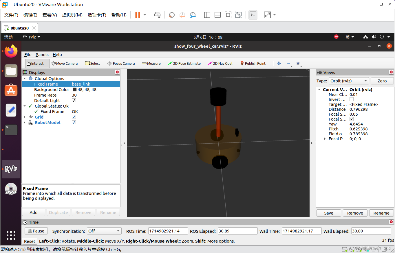
和之前一样的命令启动launch文件,在rviz中显示机器人
三、控制模拟机器人小车运动
3.1 Arbotix简介
Arbotix:Arbotix 是一款控制电机、舵机的控制板,并提供相应的 ros 功能包,这个功能包的功能不仅可以驱动真实的 Arbotix 控制板,它还提供一个差速控制器,通过接受速度控制指令更新机器人的 joint 状态,从而帮助我们实现机器人在 rviz 中的运动。
这个差速控制器在 arbotix_python 程序包中,完整的 arbotix 程序包还包括多种控制器,分别对应 dynamixel 电机、多关节机械臂以及不同形状的夹持器。
3.2 使用流程
需求描述:
控制机器人模型在 rviz 中做圆周运动
实现流程:
1.安装 Arbotix
2.创建新功能包,准备机器人 urdf、xacro 文件
3.添加 Arbotix 配置文件
4.编写 launch 文件配置 Arbotix
5.启动 launch 文件并控制机器人模型运动
3.3 安装 Arbotix
命令行输入
sudo apt-get install ros-noetic-arbotix
当前 ROS 版本名称我使用的是noetic版本的所以
sudo apt-get install ros-<<VersionName()>>-arbotix其中的
<<VsersionName()>> 替换的是noetic
3.4 创建新功能包,准备机器人 urdf、xacro
3.4.1. 添加 arbotix 所需的配置文件
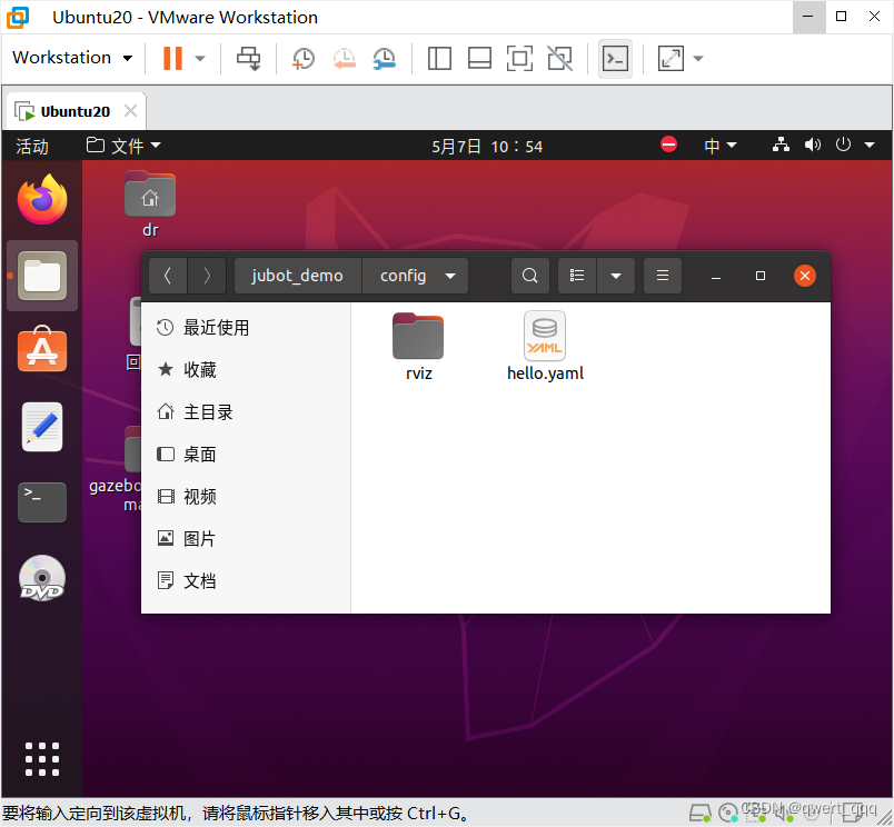
在config文件夹下新建hello.yaml文件
# 该文件是控制器配置,一个机器人模型可能有多个控制器,比如: 底盘、机械臂、夹持器(机械手)....
# 因此,根 name 是 controller
controllers: {
   # 单控制器设置
   base_controller: {
          #类型: 差速控制器
       type: diff_controller,
       #参考坐标
       base_frame_id: base_footprint,
       #两个轮子之间的间距
       base_width: 0.2,
       #控制频率
       ticks_meter: 2000,
       #PID控制参数,使机器人车轮快速达到预期速度
       Kp: 12,
       Kd: 12,
       Ki: 0,
       Ko: 50,
       #加速限制
       accel_limit: 1.0
    }
}
3.4.2 launch 文件中添加配置 arbotix 节点
<!-- 配置 arbotix 节点 -->
  <node name="arbotix" pkg="arbotix_python" type="arbotix_driver" output="screen">
    <rosparam file="$(find jubot_demo)/config/hello.yaml" command="load" />
    <param name="sim" value="true" />
  </node>
代码解释:
调用了 arbotix_python 功能包下的 arbotix_driver 节点
arbotix 驱动机器人运行时,需要获取机器人信息,可以通过 file 加载配置文件
在仿真环境下,需要配置 sim 为 true
3.4.3 启动 launch 文件并控制机器人模型运动
启动launch文件,新建一个终端窗口
调用 rostopic list
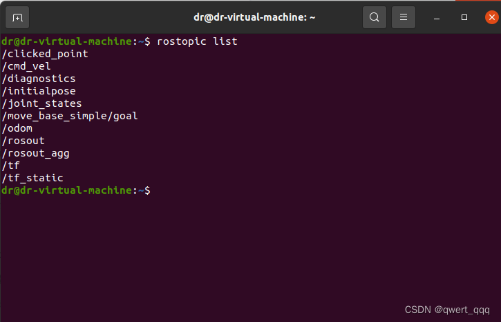
也就说我们可以发布 cmd_vel 话题消息控制小车运动了,该实现策略有多种,可以另行编写节点,或者更简单些可以直接通过如下命令发布消息:
rostopic pub -r 10 /cmd_vel geometry_msgs/Twist '{linear: {x: 0.2, y: 0, z: 0}, angular: {x: 0, y: 0, z: 0.5}}'
小车就运动起来了。
四、URDF集成Gazebo
4.1 相关设置
创建一个新的文件夹
mkdir catkin_urdf_gazebo
cd catkin_urdf_gazebo
mkdir src
catkin_make
source devel/setup.bash
cd src
catkin_create_pkg urdf_gazebo urdf xacro gazebo_ros gazebo_ros_control gazebo_plugins
cd urdf_gazebo
mkdir launch //存储launch文件
mkdir urdf //存储urdf文件的目录
cd urdf
mkdir urdf
mkdir xacro
在URDF建模篇中,我们已经学习了相关的标签,由于在gazebo中要考虑碰撞属性和和惯性矩阵,在这里,特别对碰撞属性和惯性矩阵的设置进行说明。
1、collision
如果机器人link是标准的几何体形状,和link的 visual 属性设置一致即可。
2、inertial
惯性矩阵的设置需要结合link的质量与外形参数动态生成,标准的球体、圆柱与立方体的惯性矩阵公式如下(已经封装为 xacro 实现):
4.1.1 球体惯性矩阵
<!-- Macro for inertia matrix -->
    <xacro:macro name="sphere_inertial_matrix" params="m r">
        <inertial>
            <mass value="${m}" />
            <inertia ixx="${2*m*r*r/5}" ixy="0" ixz="0"
                iyy="${2*m*r*r/5}" iyz="0"
                izz="${2*m*r*r/5}" />
        </inertial>
    </xacro:macro>
4.1.2 圆柱惯性矩阵
<xacro:macro name="cylinder_inertial_matrix" params="m r h">
        <inertial>
            <mass value="${m}" />
            <inertia ixx="${m*(3*r*r+h*h)/12}" ixy = "0" ixz = "0"
                iyy="${m*(3*r*r+h*h)/12}" iyz = "0"
                izz="${m*r*r/2}" />
        </inertial>
    </xacro:macro>
4.1.3 立方体惯性矩阵
<xacro:macro name="Box_inertial_matrix" params="m l w h">
       <inertial>
               <mass value="${m}" />
               <inertia ixx="${m*(h*h + l*l)/12}" ixy = "0" ixz = "0"
                   iyy="${m*(w*w + l*l)/12}" iyz= "0"
                   izz="${m*(w*w + h*h)/12}" />
       </inertial>
   </xacro:macro>
但是需要注意的是,原则上,除了 base_footprint 外,机器人的每个刚体部分都需要设置惯性矩阵,且惯性矩阵必须经计算得出,如果随意定义刚体部分的惯性矩阵,那么可能会导致机器人在 Gazebo 中出现抖动,移动等现象。
颜色设置:
在 gazebo 中显示 link 的颜色,必须要使用指定的标签,material 标签中,设置的值区分大小写,颜色可以设置为Red、Blue、Green、Black等等
4.2 在gazebo中导入小车模型
1、编写xacro文件
在URDF建模和xacro建模中我们已经完成了关于如何创建一个小车模型,这里以在xacro建模篇中构建的小车模型为例,修改其对应的碰撞属性和惯性矩阵,将其导入gazebo中显示。
在xacro文件夹下创建文件
gazebo_car.xacro
gazebo_camera.xacro
gazebo_laser.xacro
gazebo_head.xarco
gazebo_car_union.xacro五个文件。
gazebo_head.xacro文件:
<robot name="base" xmlns:xacro="http://wiki.ros.org/xacro">
    <xacro:macro name="sphere_inertial_matrix" params="m r">
        <inertial>
            <mass value="${m}" />
            <inertia ixx="${2*m*r*r/5}" ixy="0" ixz="0"
                iyy="${2*m*r*r/5}" iyz="0"
                izz="${2*m*r*r/5}" />
        </inertial>
    </xacro:macro>

    <xacro:macro name="cylinder_inertial_matrix" params="m r h">
        <inertial>
            <mass value="${m}" />
            <inertia ixx="${m*(3*r*r+h*h)/12}" ixy = "0" ixz = "0"
                iyy="${m*(3*r*r+h*h)/12}" iyz = "0"
                izz="${m*r*r/2}" />
        </inertial>
    </xacro:macro>

    <xacro:macro name="Box_inertial_matrix" params="m l w h">
       <inertial>
               <mass value="${m}" />
               <inertia ixx="${m*(h*h + l*l)/12}" ixy = "0" ixz = "0"
                   iyy="${m*(w*w + l*l)/12}" iyz= "0"
                   izz="${m*(w*w + h*h)/12}" />
       </inertial>
   </xacro:macro>
</robot>
gazebo_camera.xacro文件:
<robot name="my_camera" xmlns:xacro="http://wiki.ros.org/xacro">

    <xacro:property name="camera_length" value="0.01" />
    <xacro:property name="camera_width" value="0.025" />
    <xacro:property name="camera_height" value="0.025" />
    <xacro:property name="camera_x" value="0.08" />
    <xacro:property name="camera_y" value="0.0" />
    <xacro:property name="camera_z" value="${base_link_length / 2 + camera_height / 2}" />

    <xacro:property name="camera_m" value="0.01" />

    <link name="camera">
        <visual>
            <geometry>
                <box size="${camera_length} ${camera_width} ${camera_height}" />
            </geometry>
            <origin xyz="0.0 0.0 0.0" rpy="0.0 0.0 0.0" />
            <material name="black" />
        </visual>
        <collision>
            <geometry>
                <box size="${camera_length} ${camera_width} ${camera_height}" />
            </geometry>
            <origin xyz="0.0 0.0 0.0" rpy="0.0 0.0 0.0" />
        </collision>
        <xacro:Box_inertial_matrix m="${camera_m}" l="${camera_length}" w="${camera_width}" h="${camera_height}" />
    </link>

    <joint name="camera2base_link" type="fixed">
        <parent link="base_link" />
        <child link="camera" />
        <origin xyz="${camera_x} ${camera_y} ${camera_z}" />
    </joint>
    <gazebo reference="camera">
        <material>Gazebo/Blue</material>
    </gazebo>
</robot>
gazebo_laser.xacro文件:
<robot name="my_laser" xmlns:xacro="http://wiki.ros.org/xacro">

    <xacro:property name="support_length" value="0.15" />
    <xacro:property name="support_radius" value="0.01" />
    <xacro:property name="support_x" value="0.0" />
    <xacro:property name="support_y" value="0.0" />
    <xacro:property name="support_z" value="${base_link_length / 2 + support_length / 2}" />

    <xacro:property name="support_m" value="0.02" />

    <link name="support">
        <visual>
            <geometry>
                <cylinder radius="${support_radius}" length="${support_length}" />
            </geometry>
            <origin xyz="0.0 0.0 0.0" rpy="0.0 0.0 0.0" />
            <material name="red">
                <color rgba="0.8 0.2 0.0 0.8" />
            </material>
        </visual>

        <collision>
            <geometry>
                <cylinder radius="${support_radius}" length="${support_length}" />
            </geometry>
            <origin xyz="0.0 0.0 0.0" rpy="0.0 0.0 0.0" />
        </collision>

        <xacro:cylinder_inertial_matrix m="${support_m}" r="${support_radius}" h="${support_length}" />

    </link>

    <joint name="support2base_link" type="fixed">
        <parent link="base_link" />
        <child link="support" />
        <origin xyz="${support_x} ${support_y} ${support_z}" />
    </joint>

    <gazebo reference="support">
        <material>Gazebo/White</material>
    </gazebo>

    <xacro:property name="laser_length" value="0.05" />
    <xacro:property name="laser_radius" value="0.03" />
    <xacro:property name="laser_x" value="0.0" />
    <xacro:property name="laser_y" value="0.0" />
    <xacro:property name="laser_z" value="${support_length / 2 + laser_length / 2}" />

    <xacro:property name="laser_m" value="0.1" />

    <link name="laser">
        <visual>
            <geometry>
                <cylinder radius="${laser_radius}" length="${laser_length}" />
            </geometry>
            <origin xyz="0.0 0.0 0.0" rpy="0.0 0.0 0.0" />
            <material name="black" />
        </visual>
        <collision>
            <geometry>
                <cylinder radius="${laser_radius}" length="${laser_length}" />
            </geometry>
            <origin xyz="0.0 0.0 0.0" rpy="0.0 0.0 0.0" />
        </collision>
        <xacro:cylinder_inertial_matrix m="${laser_m}" r="${laser_radius}" h="${laser_length}" />
    </link>

    <joint name="laser2support" type="fixed">
        <parent link="support" />
        <child link="laser" />
        <origin xyz="${laser_x} ${laser_y} ${laser_z}" />
    </joint>
    <gazebo reference="laser">
        <material>Gazebo/Black</material>
    </gazebo>
</robot>
gazebo_car.xacro文件:
<robot name="my_base" xmlns:xacro="http://www.ros.org/wiki/xacro">

    <xacro:property name="PI" value="3.1415926"/>

    <material name="black">
        <color rgba="0.0 0.0 0.0 1.0" />
    </material>

    <xacro:property name="base_footprint_radius" value="0.001" />
    <xacro:property name="base_link_radius" value="0.1" />
    <xacro:property name="base_link_length" value="0.08" />
    <xacro:property name="earth_space" value="0.015" />
    <xacro:property name="base_link_m" value="0.5" />

    <link name="base_footprint">
      <visual>
        <geometry>
          <sphere radius="${base_footprint_radius}" />
        </geometry>
      </visual>
    </link>

    <link name="base_link">
      <visual>
        <geometry>
          <cylinder radius="${base_link_radius}" length="${base_link_length}" />
        </geometry>
        <origin xyz="0 0 0" rpy="0 0 0" />
        <material name="yellow">
          <color rgba="0.5 0.3 0.0 0.5" />
        </material>
      </visual>
      <collision>
        <geometry>
          <cylinder radius="${base_link_radius}" length="${base_link_length}" />
        </geometry>
        <origin xyz="0 0 0" rpy="0 0 0" />
      </collision>
      <xacro:cylinder_inertial_matrix m="${base_link_m}" r="${base_link_radius}" h="${base_link_length}" />

    </link>

    <joint name="base_link2base_footprint" type="fixed">
      <parent link="base_footprint" />
      <child link="base_link" />
      <origin xyz="0 0 ${earth_space + base_link_length / 2 }" />
    </joint>
    <gazebo reference="base_link">
        <material>Gazebo/Yellow</material>
    </gazebo>

    <xacro:property name="wheel_radius" value="0.0325" />
    <xacro:property name="wheel_length" value="0.015" />
    <xacro:property name="wheel_m" value="0.05" />

    <xacro:macro name="add_wheels" params="name flag">
      <link name="${name}_wheel">
        <visual>
          <geometry>
            <cylinder radius="${wheel_radius}" length="${wheel_length}" />
          </geometry>
          <origin xyz="0.0 0.0 0.0" rpy="${PI / 2} 0.0 0.0" />
          <material name="black" />
        </visual>
        <collision>
          <geometry>
            <cylinder radius="${wheel_radius}" length="${wheel_length}" />
          </geometry>
          <origin xyz="0.0 0.0 0.0" rpy="${PI / 2} 0.0 0.0" />
        </collision>
        <xacro:cylinder_inertial_matrix m="${wheel_m}" r="${wheel_radius}" h="${wheel_length}" />

      </link>

      <joint name="${name}_wheel2base_link" type="continuous">
        <parent link="base_link" />
        <child link="${name}_wheel" />
        <origin xyz="0 ${flag * base_link_radius} ${-(earth_space + base_link_length / 2 - wheel_radius) }" />
        <axis xyz="0 1 0" />
      </joint>

      <gazebo reference="${name}_wheel">
        <material>Gazebo/Red</material>
      </gazebo>

    </xacro:macro>
    <xacro:add_wheels name="left" flag="1" />
    <xacro:add_wheels name="right" flag="-1" />

    <xacro:property name="support_wheel_radius" value="0.0075" />
    <xacro:property name="support_wheel_m" value="0.03" />

    <xacro:macro name="add_support_wheel" params="name flag" >
      <link name="${name}_wheel">
        <visual>
            <geometry>
                <sphere radius="${support_wheel_radius}" />
            </geometry>
            <origin xyz="0 0 0" rpy="0 0 0" />
            <material name="black" />
        </visual>
        <collision>
            <geometry>
                <sphere radius="${support_wheel_radius}" />
            </geometry>
            <origin xyz="0 0 0" rpy="0 0 0" />
        </collision>
        <xacro:sphere_inertial_matrix m="${support_wheel_m}" r="${support_wheel_radius}" />
      </link>

      <joint name="${name}_wheel2base_link" type="continuous">
          <parent link="base_link" />
          <child link="${name}_wheel" />
          <origin xyz="${flag * (base_link_radius - support_wheel_radius)} 0 ${-(base_link_length / 2 + earth_space / 2)}" />
          <axis xyz="1 1 1" />
      </joint>
      <gazebo reference="${name}_wheel">
        <material>Gazebo/Red</material>
      </gazebo>
    </xacro:macro>

    <xacro:add_support_wheel name="front" flag="1" />
    <xacro:add_support_wheel name="back" flag="-1" />

</robot>
gazebo_car_union.xacro文件:
<robot name="my_car_camera" xmlns:xacro="http://wiki.ros.org/xacro">
    <xacro:include filename="gazebo_head.xacro" />
    <xacro:include filename="gazebo_car.xacro" />
    <xacro:include filename="gazebo_laser.xacro" />
    <xacro:include filename="gazebo_camera.xacro" />
</robot>
4.3 编写launch文件
在launch文件夹下创建一个文件,文件名为gazebo_car.launch
<launch>
    <!-- 将 Urdf 文件的内容加载到参数服务器 -->
    <param name="robot_description" command="$(find xacro)/xacro $(find urdf_gazebo)/urdf/xacro/gazebo_car_union.xacro" />
    <!-- 启动 gazebo -->
    <include file="$(find gazebo_ros)/launch/empty_world.launch" />

    <!-- 在 gazebo 中显示机器人模型 -->
    <node pkg="gazebo_ros" type="spawn_model" name="model" args="-urdf -model mycar -param robot_description"  />
</launch>
4.4 运行launch文件
catkin_make
catkin_make install
source devel/setup.bash
echo $ROS_PACKAGE_PATH
roslaunch urdf_gazebo gazebo_car.launch
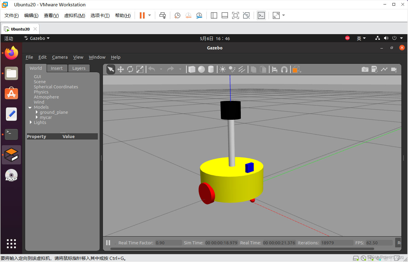
运行结果如图所示,成功将xacro模型文件导入到了gazebo中,实现了URDF集成gazebo。


 1517
1517

 被折叠的 条评论
为什么被折叠?
被折叠的 条评论
为什么被折叠?
 到【灌水乐园】发言


