


【Moveit】step或stl文件转urdf,并添加到机械臂上
文章目录
ROS专门提供了一种机器人建模方法——URDF,用来描述机器人外观、性能等各方面属性。所以我们需要将别的描述格式转换成URDF,才能在ROS中使用。
1. 安装sw_urdf_exporter插件
参考官方给出的wiki page:sw_urdf_exporter/Tutorials
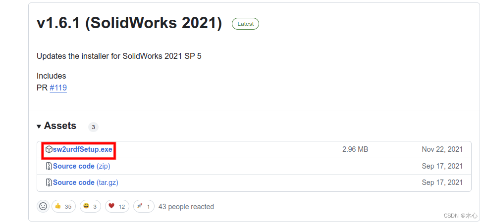
我们需要给solideworks下载一个插件,插件地址为:SolidWorks to URDF Exporter,其github的release为:https://github.com/ros/solidworks_urdf_exporter/releases
注意solideworks的版本不能过高,这个插件支持solidworks的版本为(2018SP5~2021),我们安装的时候可以直接下载这个.exe可执行文件即可,然后默认安装
2. 导出urdf
具体的操作可以参考这个视频:[ROS] Solidworks导出urdf
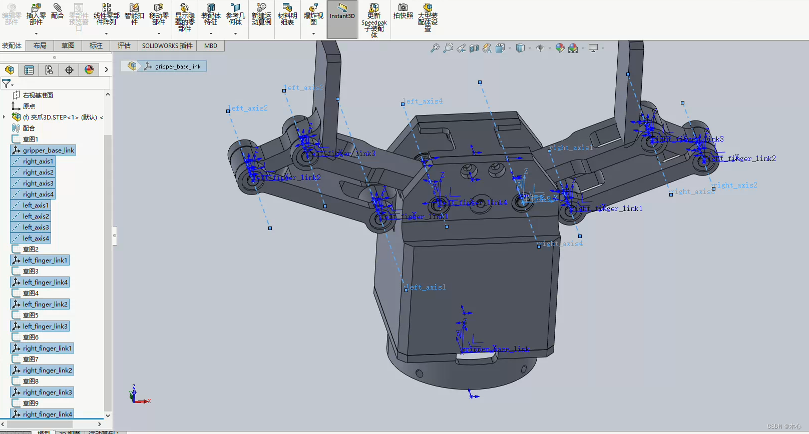
然后按照教程中的方式进行导出即可。这里我导出了一个夹爪,如下所示
导出的结果会生成一个ROS的功能包,其目录结果如下
.
├── CMakeLists.txt
├── config
│   └── joint_names_gripper_urdf3.yaml
├── export.log
├── launch
│   ├── display.launch
│   └── gazebo.launch
├── meshes
│   └── base_link.STL
├── package.xml
├── textures
└── urdf
    ├── gripper_urdf3.csv
    └── gripper_urdf3.urdf

5 directories, 9 files
我们可以使用其display.launch来查看模型是否正确,但是首先得使用catkin_make来进行编译一下,我的显示结果如下
roslaunch gripper_urdf display.launch
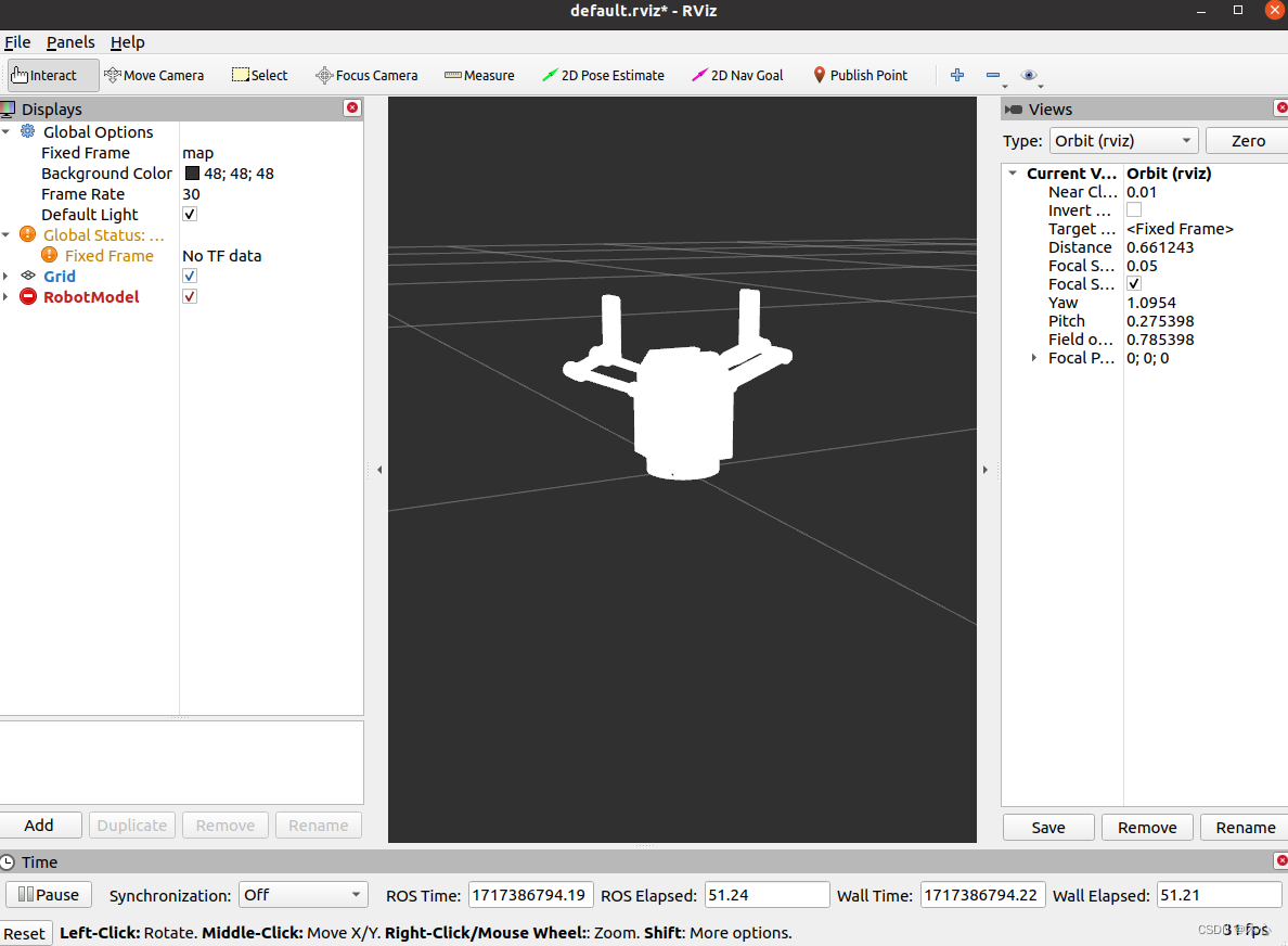
打开rviz之后,我们需要手动添加RobotModel,添加完毕后即可显示
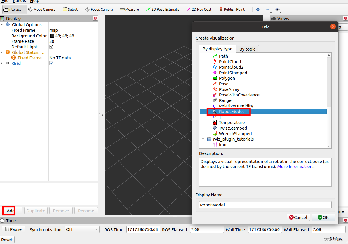
显示的效果如下:
3. 将夹爪连接到机械臂上
在导出的功能包中最重要的内容是meshs目录中的.stl文件,这是我们夹爪的模型外观,还有就是urdf目录中的gripper_urdf3.urdf文件,这个是根据.stl模型文件生成的ROS下的URDF机器人描述文件,我们可以复制其中的部分,然后将其粘贴到我们的机械臂的URDF中。
值得注意的是,link-joint-link是urdf的基本结构,示意如下
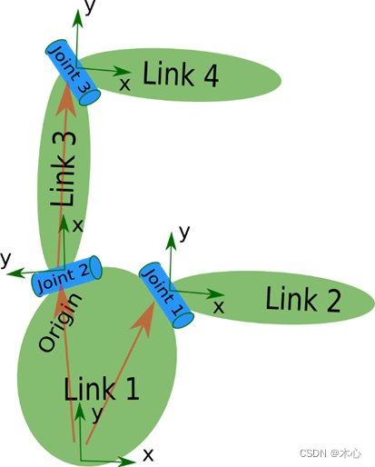
我们在编写joint时,需要指定其类型,一共有这么四种类型可以指定
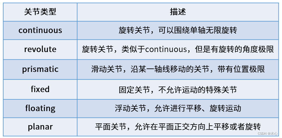
夹爪的基座相对于机械臂是固定的,所以我们在指定夹爪的基座到机械臂的末端的这个joint的时候,一定要选择fixed类型,具体可以这么写
	<joint name="gripper_joint" type="fixed">
	    <origin rpy="0 0 0" xyz="0 0 0.107" />	#xyz rpy是你的夹爪相对于机械臂的姿态
	    <parent link="wrist3_Link" />	#改为你的机械臂的最后一个link
	    <child link="arm_hand_link0" /> #改为你的gripper的base link
	    <axis xyz="0 0 0" />
	</joint>
在定义完这个joint之后,我们就可以将之前生成的URDF中的内容复制到其中,如下是我生成的内容
    </joint>
    <link name="arm_hand_link0">
        <inertial>
            <origin xyz="-2.12153840077004E-06 9.05398824170634E-05 0.0527906490348432" rpy="0 0 0" />
            <mass value="0.113713405635938" />
            <inertia ixx="5.00996061302902E-05" ixy="3.81710319217012E-10" ixz="2.12328984939388E-10" iyy="5.98637675434999E-05" iyz="-3.29078206892533E-08" izz="6.10777596321381E-05" />
        </inertial>
        <visual>
            <origin xyz="0 0 0" rpy="0 0 0" />
            <geometry>
                <mesh filename="package://frcobot_description/meshes/fr5/collision/hand_1.STL" />
            </geometry>
            <material name="">
                <color rgba="0.792156862745098 0.819607843137255 0.933333333333333 1" />
            </material>
        </visual>
        <collision>
            <origin xyz="0 0 0" rpy="0 0 0" />
            <geometry>
                <mesh filename="package://frcobot_description/meshes/fr5/collision/hand_1.STL" />
            </geometry>
        </collision>
    </link>
    <transmission name="trans_j1">
        <type>transmission_interface/SimpleTransmission</type>
        <joint name="j1">
            <hardwareInterface>hardware_interface/EffortJointInterface</hardwareInterface>
        </joint>
        <actuator name="j1_motor">
            <hardwareInterface>hardware_interface/EffortJointInterface</hardwareInterface>
            <mechanicalReduction>1</mechanicalReduction>
        </actuator>
    </transmission>
    <transmission name="trans_j2">
        <type>transmission_interface/SimpleTransmission</type>
        <joint name="j2">
            <hardwareInterface>hardware_interface/EffortJointInterface</hardwareInterface>
        </joint>
        <actuator name="j2_motor">
            <hardwareInterface>hardware_interface/EffortJointInterface</hardwareInterface>
            <mechanicalReduction>1</mechanicalReduction>
        </actuator>
    </transmission>
    <transmission name="trans_j3">
        <type>transmission_interface/SimpleTransmission</type>
        <joint name="j3">
            <hardwareInterface>hardware_interface/EffortJointInterface</hardwareInterface>
        </joint>
        <actuator name="j3_motor">
            <hardwareInterface>hardware_interface/EffortJointInterface</hardwareInterface>
            <mechanicalReduction>1</mechanicalReduction>
        </actuator>
    </transmission>
    <transmission name="trans_j4">
        <type>transmission_interface/SimpleTransmission</type>
        <joint name="j4">
            <hardwareInterface>hardware_interface/EffortJointInterface</hardwareInterface>
        </joint>
        <actuator name="j4_motor">
            <hardwareInterface>hardware_interface/EffortJointInterface</hardwareInterface>
            <mechanicalReduction>1</mechanicalReduction>
        </actuator>
    </transmission>
    <transmission name="trans_j5">
        <type>transmission_interface/SimpleTransmission</type>
        <joint name="j5">
            <hardwareInterface>hardware_interface/EffortJointInterface</hardwareInterface>
        </joint>
        <actuator name="j5_motor">
            <hardwareInterface>hardware_interface/EffortJointInterface</hardwareInterface>
            <mechanicalReduction>1</mechanicalReduction>
        </actuator>
    </transmission>
    <transmission name="trans_j6">
        <type>transmission_interface/SimpleTransmission</type>
        <joint name="j6">
            <hardwareInterface>hardware_interface/EffortJointInterface</hardwareInterface>
        </joint>
        <actuator name="j6_motor">
            <hardwareInterface>hardware_interface/EffortJointInterface</hardwareInterface>
            <mechanicalReduction>1</mechanicalReduction>
        </actuator>
    </transmission>
    <gazebo>
        <plugin name="gazebo_ros_control">
            <robotNamespace>/</robotNamespace>
        </plugin>
    </gazebo>
注意这里的package://需要更改为你存放这个urdf的包的名字,我这里是将其复制了一份,统一放置在了fr_description这个包中了,请将这里修改为你的放置路径。
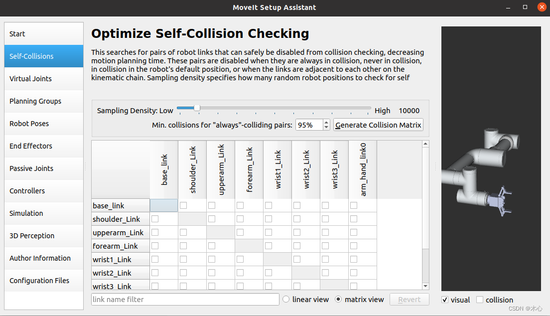
4. 使用moveit_setup_assistant配置功能包
修改完毕后,我们就可以使用moveit_setup_assisatant来配置或者修改功能包了,
roslaunch moveit_setup_assistant setup_assistant.launch
如下所示,我们能看到夹爪正确地显示了


 1687
1687

 被折叠的 条评论
为什么被折叠?
被折叠的 条评论
为什么被折叠?
 到【灌水乐园】发言


