


 本文介绍了一种实验,通过UART传输100x100像素信息到LCD显示器,并对比了使用HDMI的多媒体接口,详细阐述了编码模块和像素产生的过程。着重展示了如何通过串行数据转换实现实时图像显示。
实验目标:先显示彩条,通过uart串口传输100x100 大小图片像素信息,然后开始弹跳显示该图片在显示器上。
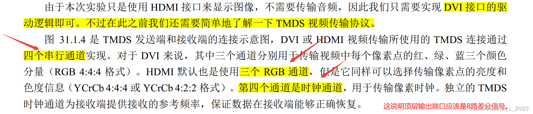
HDMI 是新一代的多媒体接口标准, 英文全称是 High-Definition Multimedia Interface, 即高清多媒体接口。 它能够同时传输视频和音频,简化了设备的接口和连线;同时提供了更高的数据传输带宽, 可以传输无压缩的数字音频及高分辨率视频信号。 HDMI 1.0 版本于 2002 年发布, 最高数据传输速度为 5Gbps; HDMI2.0
版本于 2013 年推出的, 2.0 理论传输速度能达到 18Gbit/s,实际传输速度能达到 14.4Gbit/s; 而 2017 年发布的 HDMI 2.1 标准的理论带宽可达 48Gbps,实际速度也能达到 42.6Gbit/s。

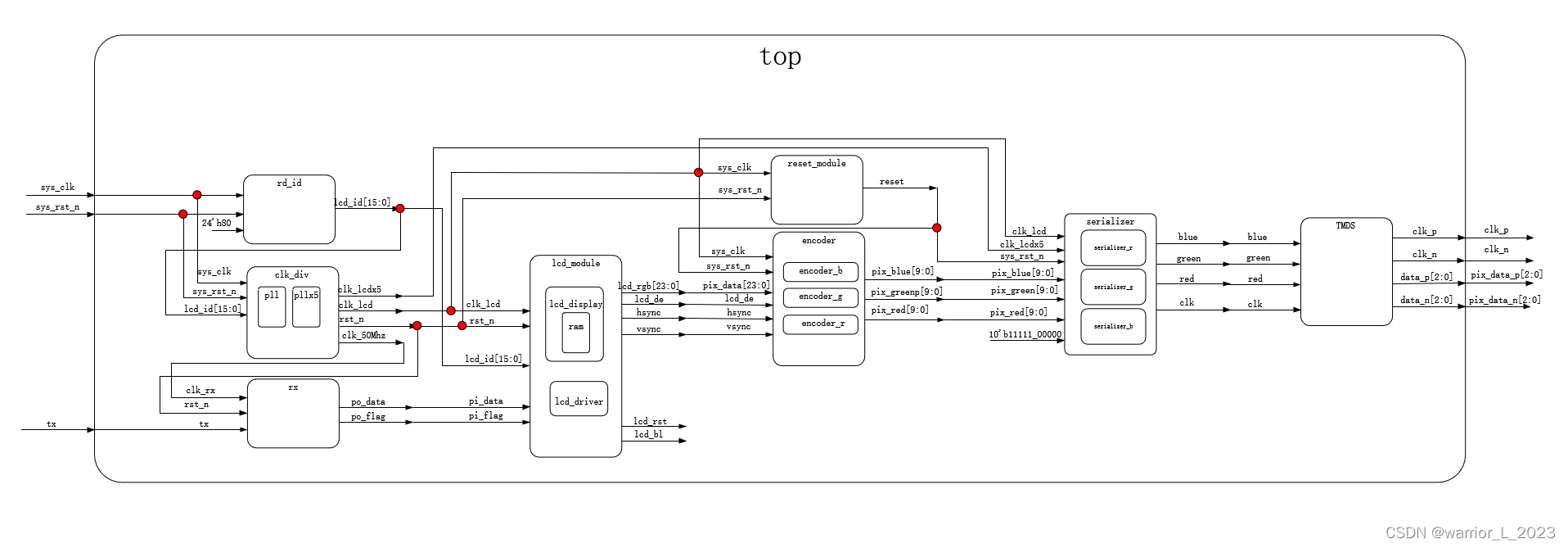
模块框图:
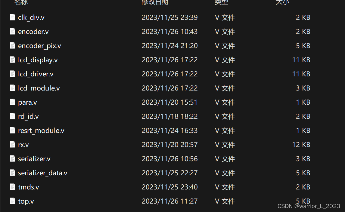
代码:
(与上一个vga显示相比,多了编码模块,串行转并行模块,单端信号转差分信号模块。)
用的是官方给的编码模块,与原语(就相当于开源的简单IP核心)。
只需要进行例化连线即可。
重点讲解像素产生模块:
首先产生彩条像素,当ram中数据存储超过10000个像素信息后,开始在规定范围内,以跳跃的方式显示该图片。
// 根据传进来的有效图像坐标信息,产生有效的像素数据�?
module lcd_display (
    input       wire                sys_clk     , // lcd的时钟,用来读取ram�?数�??
    input       wire                sys_rst_n   ,
    input       wire                clk_wr_ram  , // 50Mhz,与rx模块相同时钟�?
    input       wire    [10:0]      axi_x       , // 直接传递有效坐标数据,其余时刻为0
    input       wire    [10:0]      axi_y       , // 直接传递有效坐标数据,其余时刻为0
    input       wire    [7:0]       pi_data     ,
    input       wire                pi_flag     ,
    input       wire                finish_falg ,

    input       wire    [10:0]      H_SYNC      ,
    input       wire    [10:0]      H_BACK      ,
    input       wire    [10:0]      H_DISP      ,
    input       wire    [10:0]      V_SYNC      ,
    input       wire    [10:0]      V_BACK      ,
    input       wire    [10:0]      V_DISP      ,

    output      reg     [23:0]      pix_data
);
    localparam  BLACK       = 24'h000000 , // 黑色
                WHITE       = 24'hFFFFFF , // 白色
                RosyBrown   = 24'hBC8F8F , // �?瑰�??
                RED         = 24'hFF0000 , // 红色
                APRICOT     = 24'hE69966 , // 杏黄�?
                VIOLET      = 24'h8B00FF , // �?罗兰�?
                LINEN       = 24'hFAF0E6 , // 亚麻�?
                KHAKI       = 24'h996B1F , // 卡其�?
                PEACH       = 24'hFFE5B4 , // 桃色
                GOLDEN      = 24'hFFD700 , // 金色
                SkyBule     = 24'h87CEEB ; // 天空�?
    localparam  PIC_SIZE    = 11'd100    , // 正方形图片像素大�?100*100
                H_BYOND     = 11'd350    ,
                V_BYOND     = 11'd190    ;
    localparam  DEEP        = 18'd10_000 ; // ram深度
    // reg signal define
    reg     [ 7:0]      data1       ;
    reg     [ 7:0]      data2       ;
    reg     [ 7:0]      data3       ;
    reg     [ 1:0]      cnt_data    ;
    reg                 data_flag   ;
    reg     [13:0]      wr_addr     ;
    reg     [23:0]      wr_data     ;
    reg                 wr_en       ;
    reg     [13:0]      rd_addr     ;
    reg                 data_done   ;

    reg                 left_flag   ;
    reg                 down_flag   ;
    reg     [10:0]      cnt_h       ;
    reg     [10:0]      cnt_l       ;

    // wire signal define
    wire                wr_en_r     ;
    wire    [13:0]      wr_addr_r   ;
    wire    [23:0]      wr_data_r   ;
    wire    [13:0]      rd_addr_r   ;
    wire                all_en      ;
    wire                rd_en       ;
    wire    [23:0]      rd_data     ;
/******************************************************************************************
********************************************main code**************************************
*******************************************************************************************/
    // // reg signal define
    // reg     [ 7:0]      data1       ;
    always @(posedge clk_wr_ram or negedge sys_rst_n) begin
        if(~sys_rst_n)
            data1 <= 8'd0 ;
        else if(pi_flag && (cnt_data == 0))
            data1 <= pi_data ;
        else
            data1 <= data1 ;
    end
    // reg     [ 7:0]      data2       ;
    always @(posedge clk_wr_ram or negedge sys_rst_n) begin
        if(~sys_rst_n)
            data2 <= 8'd0 ;
        else if(pi_flag && (cnt_data == 1))
            data2 <= pi_data ;
        else
            data2 <= data2 ;
    end
    // reg     [ 7:0]      data3       ;
    always @(posedge clk_wr_ram or negedge sys_rst_n) begin
        if(~sys_rst_n)
            data3 <= 8'd0 ;
        else if(pi_flag && (cnt_data == 2))
            data3 <= pi_data ;
        else
            data3 <= data3 ;
    end
    // reg     [ 1:0]      cnt_data    ;
    always @(posedge clk_wr_ram or negedge sys_rst_n) begin
        if(~sys_rst_n)
            cnt_data <= 2'd0 ;
        else if(pi_flag && cnt_data == 2)
            cnt_data <= 2'd0 ;
        else if(pi_flag)
            cnt_data <= cnt_data + 1'b1 ;
        else
            cnt_data <= cnt_data ;
    end
    // reg                 data_flag   ;
    always @(posedge clk_wr_ram or negedge sys_rst_n) begin
        if(~sys_rst_n)
            data_flag <= 1'b0 ;
        else if(pi_flag && cnt_data == 2)
            data_flag <= 1'b1 ;
        else
            data_flag <= 1'b0 ;
    end
    // reg     [13:0]      wr_addr     ;
    always @(posedge clk_wr_ram or negedge sys_rst_n) begin
        if(~sys_rst_n)
            wr_addr <= 14'd0 ;
        else if(wr_en &&( wr_addr == DEEP - 1))
            wr_addr <= 14'd0 ;
        else if(wr_en)
            wr_addr <= wr_addr + 1'b1 ;
        else
            wr_addr <= wr_addr ;
    end
    // reg     [23:0]      wr_data     ;
    always @(posedge clk_wr_ram or negedge sys_rst_n) begin
        if(~sys_rst_n)
            wr_data <= 24'd0 ;
        else if(data_flag)
            wr_data <= {data1,data2,data3} ;
        else
            wr_data <= wr_data ;
    end
    // reg                 wr_en       ;
    always @(posedge clk_wr_ram or negedge sys_rst_n) begin
        if(~sys_rst_n)
            wr_en <= 1'b0 ;
        else
            wr_en <= data_flag ;
    end
    // reg     [13:0]      rd_addr     ; // 读地址的时钟与lcd_clk相同
    always @(posedge sys_clk or negedge sys_rst_n) begin
        if(~sys_rst_n)
            rd_addr <= 14'd0 ;
        else if((rd_en && rd_addr == DEEP - 1) || (finish_falg))
            rd_addr <= 14'd0 ;
        else if(rd_en)
            rd_addr <= rd_addr + 1'b1 ;
        else
            rd_addr <= rd_addr ;
    end
    // reg    left_flag     一帧图像显示完,再进行计数。
    always @(posedge sys_clk or negedge sys_rst_n) begin
        if(~sys_rst_n)
            left_flag <= 1'b1 ;
        else if(left_flag && (cnt_h == (H_DISP - PIC_SIZE - 1)))
            left_flag <= 1'b0 ;
        else if((!left_flag) && (cnt_h == 0))
            left_flag <= 1'b1 ;
        else
            left_flag <= left_flag ;
    end
    // reg     [10:0]      cnt_h       ; 行计数器
    always @(posedge sys_clk or negedge sys_rst_n) begin
        if(~sys_rst_n)
            cnt_h <= 11'd0 ; // 初始显示在左上角
        else if(left_flag && finish_falg)
            cnt_h <= cnt_h + 1'b1 ;
        else if(!left_flag && finish_falg)
            cnt_h <= cnt_h - 1'b1 ;
        else
            cnt_h <= cnt_h ;
    end
    // reg    down_flag
    always @(posedge sys_clk or negedge sys_rst_n) begin
        if(~sys_rst_n)
            down_flag <= 1'b1 ;
        else if(down_flag && (cnt_l == (V_DISP - PIC_SIZE - 1)))
            down_flag <= 1'b0 ;
        else if((!down_flag) && (cnt_l == 0))
            down_flag <= 1'b1 ;
        else
            down_flag <= down_flag ;
    end
    // reg     [10:0]      cnt_l       ; 列计数器
    always @(posedge sys_clk or negedge sys_rst_n) begin
        if(~sys_rst_n)
            cnt_l <= 11'd0 ; // 初始显示在左上角
        else if(down_flag && finish_falg)
            cnt_l <= cnt_l + 1'b1 ;
        else if(!down_flag && finish_falg)
            cnt_l <= cnt_l - 1'b1 ;
        else
            cnt_l <= cnt_l ;
    end
    // reg     [10:0]      cnt_l       ;
    // wire signal define
    // wire                wr_en_r     ;
    assign              wr_en_r     = wr_en   ;
    // wire    [13:0]      wr_addr_r   ;
    assign              wr_addr_r   = wr_addr ;
    // wire    [23:0]      wr_data_r   ;
    assign              wr_data_r   = wr_data ;
    // wire    [13:0]      rd_addr_r   ;
    assign              rd_addr_r   = rd_addr ;
    // wire                all_en      ;
    assign  all_en = 1'b1 ;
    // wire                rd_en       ;
    // assign  rd_en = ((axi_y >= V_SYNC + V_BACK + V_BYOND) && (axi_y <= V_SYNC + V_BACK + V_BYOND + PIC_SIZE - 1)
    //                 && (axi_x >= H_SYNC + H_BACK + H_BYOND) && (axi_x <= H_SYNC + H_BACK + H_BYOND + PIC_SIZE - 1)) ? 1'b1 : 1'b0 ;

    //reg  data_done ;
    always @(posedge sys_clk or negedge sys_rst_n) begin
        if(~sys_rst_n)
            data_done <= 1'b0 ;
        else if(wr_addr_r == DEEP - 1)
            data_done <= 1'b1 ;
        else
            data_done <= data_done ;
    end

    assign  rd_en = (((axi_y >= cnt_l + V_SYNC + V_BACK) && (axi_y <= cnt_l + V_SYNC + V_BACK + PIC_SIZE - 1)
                &&  ((axi_x >= cnt_h + H_SYNC + H_BACK) && (axi_x <= cnt_h + H_SYNC + H_BACK + PIC_SIZE - 1))) && data_done) ? 1'b1 : 1'b0 ;
    // wire    [23:0]      rd_data     ;
    // wire    [23:0]      rd_data     ;
    // output pix_data
    always @(posedge sys_clk or negedge sys_rst_n) begin
        if(~sys_rst_n)
            pix_data <= BLACK ;
        else if((axi_y >= V_SYNC + V_BACK) && (axi_y <= V_SYNC + V_BACK + V_DISP - 1)) begin// 在场同�?�有效区间�??
                if(rd_en) begin
                    pix_data <= rd_data ;
                end
                else begin
                    if((axi_x >= H_SYNC + H_BACK) && (axi_x <= H_SYNC + H_BACK + H_DISP/10 - 1))
                        pix_data <= WHITE ;
                    else
                    if((axi_x >= H_SYNC + H_BACK + H_DISP/10) && (axi_x <= H_SYNC + H_BACK + (H_DISP/10)*2 - 1))
                        pix_data <= BLACK ;
                    else
                    if((axi_x >= H_SYNC + H_BACK + (H_DISP/10)*2) && (axi_x <= H_SYNC + H_BACK + (H_DISP/10)*3 - 1))
                        pix_data <= RosyBrown ;
                    else
                    if((axi_x >= H_SYNC + H_BACK + (H_DISP/10)*3) && (axi_x <= H_SYNC + H_BACK + (H_DISP/10)*4 - 1))
                        pix_data <= APRICOT ;
                    else
                    if((axi_x >= H_SYNC + H_BACK + (H_DISP/10)*4) && (axi_x <= H_SYNC + H_BACK + (H_DISP/10)*5 - 1))
                        pix_data <= RED ;
                    else
                    if((axi_x >= H_SYNC + H_BACK + (H_DISP/10)*5) && (axi_x <= H_SYNC + H_BACK + (H_DISP/10)*6 - 1))
                        pix_data <= VIOLET ;
                    else
                    if((axi_x >= H_SYNC + H_BACK + (H_DISP/10)*6) && (axi_x <= H_SYNC + H_BACK + (H_DISP/10)*7 - 1))
                        pix_data <= KHAKI ;
                    else
                    if((axi_x >= H_SYNC + H_BACK + (H_DISP/10)*7) && (axi_x <= H_SYNC + H_BACK + (H_DISP/10)*8 - 1))
                        pix_data <= PEACH ;
                    else
                    if((axi_x >= H_SYNC + H_BACK + (H_DISP/10)*8) && (axi_x <= H_SYNC + H_BACK + (H_DISP/10)*9 - 1))
                        pix_data <= GOLDEN ;
                    else
                    if((axi_x >= H_SYNC + H_BACK + (H_DISP/10)*9) && (axi_x <= H_SYNC + H_BACK + (H_DISP/10)*10 - 1))
                        pix_data <= SkyBule ;
                    else
                        pix_data <= BLACK ;
                end
            end
        else
            pix_data <= BLACK ;
    end

//  例化ram
ram_24x400x400 ram_24x400x400_inst (
    .clka                           ( clk_wr_ram    ) , // input wire clka
    .ena                            ( all_en        ) , // input wire ena
    .wea                            ( wr_en_r       ) , // input wire [0 : 0] wea
    .addra                          ( wr_addr_r     ) , // input wire [13 : 0] addra
    .dina                           ( wr_data_r     ) , // input wire [23 : 0] dina

    .clkb                           ( sys_clk       ) , // input wire clkb
    .enb                            ( rd_en         ) , // input wire enb
    .addrb                          ( rd_addr       ) , // input wire [13 : 0] addrb

    .doutb                          ( rd_data       )   // output wire [23 : 0] doutb
);

// ila_0 your_instance_name (
// 	.clk(clk_wr_ram), // input wire clk


// 	.probe0(pi_flag), // input wire [0:0]  probe0
// 	.probe1(pi_data), // input wire [7:0]  probe1
// 	.probe2(data1), // input wire [6:0]  probe2
// 	.probe3(data2), // input wire [6:0]  probe3
// 	.probe4(data3), // input wire [6:0]  probe4
// 	.probe5(wr_en_r), // input wire [0:0]  probe5
// 	.probe6(wr_addr_r), // input wire [22:0]  probe6
// 	.probe7(wr_addr_r) // input wire [13:0]  probe7
// );

// ila_0 ila_0_inst (
// 	.clk(clk_wr_ram), // input wire clk

// 	// .probe0(rd_en), // input wire [0:0]  probe0
// 	// .probe1(rd_addr), // input wire [13:0]  probe1
// 	// .probe2(rd_data), // input wire [23:0]  probe2
// 	// .probe3(wr_en_r), // input wire [0:0]  probe3
// 	// .probe4(axi_x), // input wire [10:0]  probe4
// 	// .probe5(axi_y), // input wire [10:0]  probe5
// 	.probe0( ), // input wire [0:0]  probe0
// 	.probe1( ), // input wire [13:0]  probe1
// 	.probe2( ), // input wire [23:0]  probe2
// 	.probe3( ), // input wire [0:0]  probe3
// 	.probe4( ), // input wire [10:0]  probe4
// 	.probe5( ), // input wire [10:0]  probe5

// 	.probe6(pi_flag), // input wire [0:0]  probe6
// 	.probe7(pi_data), // input wire [7:0]  probe7
// 	.probe8 (data1), // input wire [7:0]  probe8
// 	.probe9 (data2), // input wire [7:0]  probe9
// 	.probe10(data3), // input wire [7:0]  probe10
// 	.probe11(wr_data), // input wire [23:0]  probe11
// 	.probe12(cnt_data) // input wire [1:0]  probe12

// );

endmodule


 3082
3082

 被折叠的 条评论
为什么被折叠?
被折叠的 条评论
为什么被折叠?
 到【灌水乐园】发言


