树莓派多串口指南(以树莓派4B为例)

树莓派串口简介

树莓派上共有5个TTL电平的串口。其中,UART1可以直接使用,UART2、UART3、UART4、UART5需要通过引脚复用功能配置开启。

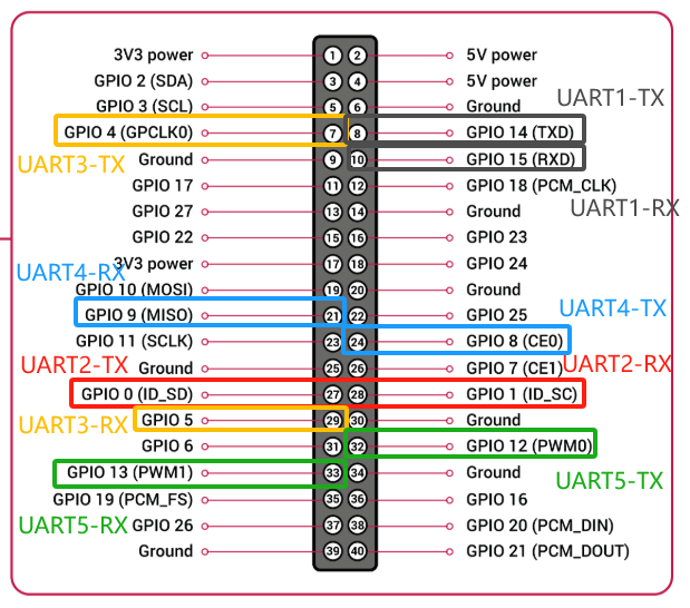
各个引脚在树莓派40Pin上的示意图如下(这里只标出了各个串口的TX和RX,实际使用时可能还需要连接VCC和Ground):

特殊的UART1

 默认情况下,UART1使用的是Mini UART,性能一般,不支持硬件流控,可能不稳定。而性能较强的PL011被分配给蓝牙模块。

如果用户不需要蓝牙,则可以将通过配置使得UART1使用性能较强的PL011,使得UART1更加稳定。详细的切换步骤请参考其他文章。

通过引脚复用功能配置开启串口

进入树莓派系统后,输入以下命令编辑配置文件:

sudo nano /boot/config.txt

如果想配置开启UART2和UART3,就在文件最末尾添加

dtoverlay=uart2
dtoverlay=uart3

同理,如果想配置开启UART4、UART5,继续依次添加即可。

编辑完成后,按下Ctrl+X保存文件,再次按下Enter确认保存。如不会使用nano编辑器,请自行查找相关教程,或使用vim编辑器。

文件保存成功后,重启树莓派:

sudo reboot now

重启完成后,在终端输入下列命令验证串口是否开启成功:

ls /dev | grep AMA

此时,你应该可以发现,除了ttyAMA0之外,在配置文件中新增了几个串口,此命令的输出结果就会多几个串口。

串口排序是按照UART的编号依次排序的。例如,用户启用UART2和UART5,此处的ttyAMA1对应UART2,ttyAMA2对应UART5。

测试脚本

配置完成后,可以通过以下Python脚本检测是否可以正常使用。

注意,运行脚本前,需要将对应串口的TX连接到RX上。

from serial import Serial
from threading import Thread
import time

def recv(uart):
    while True:
        print(uart.read())
        time.sleep(0.1)

if __name__ == "__main__":
    uart = Serial("/dev/ttyAMA2", 19200)
    
    Thread(target=recv, args=(uart,)).start()

    uart.write(b"\x01\x02")

使用nano或vim编辑文件,建议将文件名称保存为uart_test.py。

运行脚本前,需要安装Python外部依赖包。

pip install pyserial

依赖安装完成后,使用下面的命令运行脚本。

python3 uart_test.py

此时程序应当有输出。

### Raspberry Pi 4B Pinout Diagram The Raspberry Pi 4B features a 40-pin GPIO header, which provides various functions including power supply pins, ground pins, and programmable GPIO pins that can be configured as input or output to control devices like LEDs based on the described scenario[^1]. Below is an overview of these functionalities: #### Power Supply Pins - **Pin 1 (3V3)**: Provides a constant 3.3V DC voltage. - **Pin 2 & Pin 4 (5V)**: Provide a stable 5V DC voltage. #### Ground Pins - Multiple GND pins are available at positions such as Pin 6, Pin 9, Pin 14, Pin 20, Pin 25, Pin 30, Pin 34, and Pin 39 for grounding circuits. #### Programmable GPIO Pins These pins support both digital inputs and outputs with configurable pull-up/pull-down resistors: - For example, **Pin 7 (GPIO 4)** could serve as an input/output pin used to detect switch states or drive LED indicators according to the application requirements mentioned earlier. To implement signal detection using tree莓派的GPIO接口,可以利用Python编程来设置特定引脚作为输入或输出端口。通过配置这些引脚的状态变化(如高低电平转换),能够有效地控制外部设备的工作模式。 For visual reference regarding exact placement within the physical layout, refer to diagrams specifically designed for Raspberry Pi 4B models showing all 40-pins clearly labeled by their respective numbers and names. ```python import RPi.GPIO as GPIO import time # Setup channel led_pin = 18 # Example GPIO number connected to LED switch_pin = 17 # Example GPIO number connected to button/switch def setup(): GPIO.setmode(GPIO.BCM) GPIO.setup(led_pin, GPIO.OUT) GPIO.setup(switch_pin, GPIO.IN) try: while True: if GPIO.input(switch_pin): # High level detected GPIO.output(led_pin, GPIO.HIGH) # Turn on LED else: GPIO.output(led_pin, GPIO.LOW) # Turn off LED finally: GPIO.cleanup() ```
评论
添加红包

请填写红包祝福语或标题

红包个数最小为10个

红包金额最低5元

当前余额3.43前往充值 >
需支付:10.00
成就一亿技术人!
领取后你会自动成为博主和红包主的粉丝 规则
hope_wisdom
发出的红包
实付
使用余额支付
点击重新获取
扫码支付
钱包余额 0

抵扣说明:

1.余额是钱包充值的虚拟货币,按照1:1的比例进行支付金额的抵扣。
2.余额无法直接购买下载,可以购买VIP、付费专栏及课程。

余额充值