


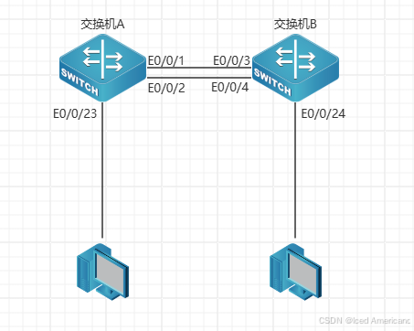
拓扑图:
题目:
将多个物理端口捆绑在一起,成 为一个逻辑端口,以实现出/入流量在各成员端口中的负荷分担,交换机根据用户配置的端口负荷分担策略决定报文从哪一个成员端口发送到对端的交换机。链路聚合在增加链路带宽、实现链路传输弹性和冗余等方面
IP地址表:
| 设备 | ip | mask | 端口 |
| 交换机A | 192.168.1.11 | 255.255.255.0 | 1-2 port–group |
| 交换机B | 192.168.1.12 | 255.255.255.0 | 3-4 port–group |
| PC1 | 192.168.1.101 | 255.255.255.0 | 交换机A端口23 |
| PC2 | 192.168.1.102 | 255.255.255.0 | 交换机B端口24 |
配置命令:
SW-A:

vlan 1

!

port-group 1 load-balance src-mac

!

Interface Ethernet0/0/1

port-group 1 mode active

!

Interface Ethernet0/0/2

port-group 1 mode active

!

Interface Port-Channel1

!

interface Vlan1

ip address 192.168.1.11 255.255.255.0
SW-B:
vlan 1
!
port-group 1 load-balance src-mac
!
Interface Ethernet0/0/3
port-group 1 mode passive
!
Interface Ethernet0/0/4
port-group 1 mode passive
!
Interface Port-Channel1
!
interface Vlan1
ip address 192.168.1.12 255.255.255.0
!


 1591
1591

 被折叠的 条评论
为什么被折叠?
被折叠的 条评论
为什么被折叠?
 到【灌水乐园】发言


