


本文主要讲如何设计飞控板,从硬件上进行DIY,并编译Ardupilot固件将DIY飞控板跑起来,实现修改一些外设支持,还有省点买高端飞控的钱。
Ardupilot飞控系统架构
Ardupilot是一个在航模圈非常知名的开源系统,可以实现对旋翼机、固定翼无人机、无人车、无人船、无人飞艇等设备的运动控制。
参考Ardupilot的系统架构,或者基于Ardupilot衍生的FMU、Pixhawk等飞控产品,可以很容易从淘宝等渠道买到DIY无人机的各种模块,从而DIY出自己的无人机来。
目前无人机系统架构大体可以分为DJI和其他,DJI的系统架构大家参考网上流传的拆机报告或者自行拆解分析,其他的可以参考基于Ardupilot的PixHawk V6X的接线框图。
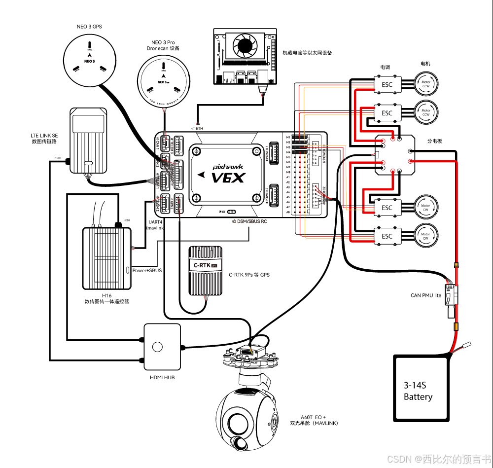
相机-数传系统与飞控无关,这里暂时不讨论;
机载电脑,没特殊需求的话用不到,这里也不讨论;
电池不用说,根据动力系统设计、电机设计进行配置即可;
PMU(Power Mangement Unit),电源管理单元,在业界也叫BEC(Battey Elimination Circuit),实际就是一个高压转低压(通常是5V)给飞控、传感器等模块使用的DCDC电路,加上一个电流检测电路,即检流电阻加上运放,飞控通过ADC采样系统电流电压;
ESC(Electronic Speed Controller),电子调速器,就是驱动无人机旋翼电机的电调驱动,根据飞控指令控制电机启停和转速,选购时需要注意与飞控的协议兼容性(PWM/PPM/CAN/UART/OneShot/DShot等),这里我们采用PWM;ESC也有一些开源方案存在,以后有机会再研究一下;
DroneCan和GPS实际就是无人机的各种传感器模块,Ardupilot飞控系统要求包括如下传感器:GPS全球定位系统、IMU惯性测量单元、Compass指南针、Barometer气压计。传感器可以通过独立的MCU获取数据后通过CAN传递给飞控,也可以由飞控MCU直接去驱动读取。这里我们采用飞控MCU直接驱动读取传感器的方案;
DSM/RC SBUS,遥控器接收机,选购遥控器和配套接收机时,需要注意接收机与遥控器的无线通信兼容性,以及接收机与飞控的数字通信协议(PPM/SBUS)是否兼容,在Ardupilot系统架构中,遥控器只是个飞行控制指令的单向上行信号,而指令执行的反馈需要通过下行的数传系统和地面站来获取,这点与一般商用无人机(穿越机除外)的上下行一体机遥控方案有较大差异。
FC,飞控模块,下文介绍如何基于Ardupilot进行自己的二次硬件开发。
DIY的准备工作
DIY的第一步,先从github下载Ardupilot源代码;
 git clone https://github.com/ArduPilot/ardupilot
 cd ardupilot
 git submodule update --init --recursive
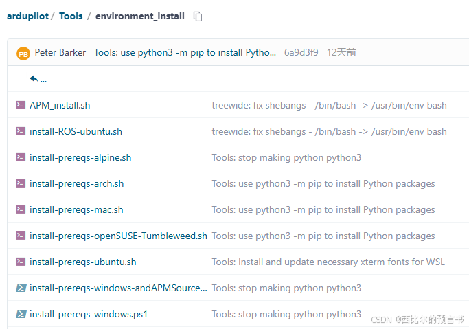
然后安装Ardupilot编译环境,Windows推荐采用WSL安装Linux虚拟机,并在虚拟机中安装编译环境;Ardupilot的源代码包含了基于Debian/Ubuntu系统的编译环境配置工具,可以在Windows WSL Ubuntu或者原生Ubuntu中执行如下脚本安装和配置编译环境;
Tools/environment_install/install-prereqs-ubuntu.sh -y
. ~/.profile
Windows或其他Linux系统安装编译环境只需要执行对应的安装脚本即可
Ardupilot的开发环境就已经安装好。
Ardupilot编译说明
在配置好开发环境后,Ardupilot采用Waf工具进行固件编译,编译指令需要注意一定在ardupilot代码的根目录执行,这点与make不同。
Ardupilot通过硬件配置文件来编译对应硬件的飞控固件;硬件配置文件在目录 ardupilot\libraries\AP_HAL ChibiOS\hwdef 之下,这个目录下有很多文件夹,每个文件夹都对应不同的飞控板,文件夹下有2个文件: hwdef.dat和hwdef_bl.dat,这两个文件就是硬件配置文件;hwdef_bl.dat是Bootloader硬件配置文件,一般进行描述的配置信息比较少,只包含启动和更新固件描述所必须的时钟、存储、板子ID、上位机串口等配置;hwdef.dat是完整的硬件配置文件,除上述信息外,还包括所有IO和外设的描述说明;
假设我们的飞控名称为DIYFC(通过地面站/设备管理器可以读取到这个ID),在 ardupilot\libraries\AP_HAL ChibiOS\hwdef 目录下也新建了名称为DIYFC的文件夹,文件夹下编辑好硬件配置文件: hwdef.dat和hwdef_bl.dat,编译过程的操作如下;
第一步,如果不是第一次编译,建议清理之前的编译中间文件,能避免很多奇怪的问题;
./waf distclean
第二步,生成Bootloader(可省略);
Tools/scripts/build_bootloaders.py DIYFC
第三步,设置编译目标为针对你的硬件的飞控固件;
./waf configure --board DIYFC
第四步,编译飞控固件(此处以编译多旋翼固件为例);
./waf copter
编译好的Bootloader和大包固件会出现在 ardupilot\bulid\DIYFC\bin\ 目录中;
以上步骤可以写个脚本执行。
硬件设计
硬件设计需要考虑这些因素:
1.MCU选型和IO分配
MCU需要是Ardupilot支持的型号,型号列表可以参考ardupilot\libraries\AP_HAL ChibiOS\hwdef\scripts下对应文件列表,IO分配可以参考源代码中某个现有的产品,在这个基础上进行修改,需要注意避免出现端口号重复分配的情况;
2.外设型号
GPS一般是通过报文协议通信,Ardupilot支持多种报文协议,具体报文类别可以参考代码目录 ardupilot\libraries\AP_GPS ,常见的模组或者芯片的报文协议都可以兼容;
IMU涉及到具体型号的驱动兼容,只能选择支持的型号,型号列表可以参考ardupilot\libraries\AP_Inertialsensor\下AP_InertialSensor_Invensensev.cpp、AP_InertialSensor_Invensensev2.cpp、AP_InertialSensor_Invensensev3.cpp描述的兼容型号,需要注意三个IMU接口支持的IMU型号可能有差异,选型和配置接口需要注意兼容;
指南针涉及到具体型号的驱动兼容,只能选择支持的型号,型号列表可以参考ardupilot\libraries\AP_Compass下的文件列表;
气压计涉及到具体型号的驱动兼容,只能选择支持的型号,型号列表可以参考ardupilot\libraries\AP_Baro下的文件列表;
具体设计可以参考基于Ardupilot的其他开源飞控板进行。
硬件配置文件说明
硬件配置文件通过源代码中的宏定义来配置一些功能,GPIO和接口名实际也是内部宏定义,通过名称可以直观理解其含义;
下面以某个产品的hwdef.dat为例进行说明,注释包括了官方的文本规则解释和本人增加的解释。
# 井号"#"开头的行表示注释内容
# hw definition file for processing by chibios_hwdef.py
# for FMUv3 hardware (ie. for Pixhawk1, Pixhawk2 cube, XUAV2.1 etc)

# This hwdef.dat file contains a lot of comments so it can act as a
# reference for developers adding new boards.

# The hwdef.dat file defines all the hardware peripherals and pins for
# a port of ArduPilot to a board using the ChibiOS HAL. You should be
# able to write the hwdef.dat file for a new board with just the
# schematic for the board.

# This file is processed by chibios_hwdef.py to create hwdef.h for
# this board. You may find it useful to run chibios_hwdef.py manually
# when building this file for a new board. The resulting hwdef.h file
# is formatted to make it quite readable. It is strongly suggested
# that you read the resulting hwdef.h file when porting to a new board
# to make sure it has resulted in what you want.

# You should read this file in conjunction with the schematic for your
# board, the datasheet for the MCU for your board and the python
# tables file that we have extracted from the datasheet for your
# MCU. The python tables file is particularly important, so if you
# haven't seen it before go and look at it now. For the STM32F427 it
# it called STM32F427xx.py and it is in the hwdef/script/ directory
# inside the HAL_ChibiOS directory. That file tells you what each pin
# can do (the alternate functions table) and what DMA channels can be
# used for each peripheral type. The alternative functions table is
# particularly useful when doing a new hwdef.dat file as you can work
# out peripheral numbers given a port/pin name.

# We need to start off by saying what main CPU is on the board. There
# are two CPU identifiers that you need to specify. The first is the
# ChibiOS MCU type. So far we only support STM32F4xx for all STM32F4
# board types. In the future we will add F7 and other MCU types
# The second string needs to match the name of a config file in the
# libraries/AP_HAL_ChibiOS/hwdef/script directory. In this case we are
# using a F427 MCU, so we select STM32F427xx to match the
# STM32F427xx.py file in the script directory. If you are supporting a
# board type that doesn't have a python hardware database file yet
# then you will need to create one. There are scripts in the scripts
# directory to help with that by parsing the STM32 datasheets to
# extract the required DMA and alternate function tables.

# MCU class and specific type
MCU STM32F4xx STM32F427xx
# 定义MCU型号系列

# We set a specific HAL_BOARD_SUBTYPE, allowing for custom config in
# drivers. For this to be used the subtype needs to be added to
# AP_HAL/AP_HAL_Boards.h as well.
define CONFIG_HAL_BOARD_SUBTYPE HAL_BOARD_SUBTYPE_CHIBIOS_FMUV3

# Now we need to specify the APJ_BOARD_ID. This is the ID that the
# bootloader presents to GCS software so it knows if this firmware is
# suitable for the board. Please see
# https://github.com/ArduPilot/Bootloader/blob/master/hw_config.h for
# a list of current board IDs. If you add a new board type then please
# get it added to that repository so we don't get conflicts.

# Note that APJ is "ArduPilot JSON Firmware Format".

# board ID for firmware load
APJ_BOARD_ID 9
# 定义飞控板Board ID,提交源代码给Ardupilot的话申请与其他厂商的ID区分的ID,本地编译运行随便写

# Now you need to say what crystal frequency you have for this
# board. All of the clocks are scaled against this. Typical values are
# 24000000 or 8000000.

# crystal frequency
OSCILLATOR_HZ 24000000
# 参考时钟的的频率,即晶体或者晶振的频率参数

# On some boards you will need to also set the various PLL values. See
# the defaults in common/mcuconf.h, and use the define mechanism
# explained later in this file to override values suitable for your
# board. Refer to your MCU datasheet or examples from supported boards
# in ChibiOS for the right values.

# Now define the voltage the MCU runs at. This is needed for ChibiOS
# to set various internal driver limits. It is in 0.01 volt units.


# This is the STM32 timer that ChibiOS will use for the low level
# driver. This must be a 32 bit timer. We currently only support
# timers 2, 3, 4, 5 and 21. See hal_st_lld.c in ChibiOS for details.

# ChibiOS system timer
STM32_ST_USE_TIMER 5
# 用到的定时器数量

# Now the size of flash in kilobytes, for creating the ld.script.

# flash size
FLASH_SIZE_KB 2048
# 选用STM32芯片内置的Flash容量

# Now define which UART is used for printf(). We rarely use printf()
# in ChibiOS, so this is really only for debugging very early startup
# in drivers.

# Serial port for stdout. This is optional. If you leave it out then
# output from printf() lines will go to the ArduPilot console, which is the
# first UART in the SERIAL_ORDER list.  But note that some startup code
# runs before USB is set up.
# The value for STDOUT_SERIAL is a serial device name, and must be for a
# serial device for which pins are defined in this file. For example, SD7
# is for UART7 (SD7 == "serial device 7" in ChibiOS).
#STDOUT_SERIAL SD7
#STDOUT_BAUDRATE 57600

# Now the USB setup, if you have USB. All of these settings are
# option, and the ones below are the defaults. It ends up creating a
# USB ID on Linux like this:
# /dev/serial/by-id/usb-ArduPilot_fmuv3_3E0031000B51353233343932-if00
# If creating a board for a RTF vehicle you may wish to customise these.

# USB setup
USB_STRING_MANUFACTURER "ArduPilot"
# 呈现给地面站或者设备管理器的厂商名

# Now define the order that I2C buses are presented in the hal.i2c API
# in ArduPilot. For historical reasons inherited from HAL_PX4 the
# 'external' I2C bus should be bus 1 in hal.i2c, and internal I2C bus
# should be bus 0. On fmuv3 the STM32 I2C1 is our external bus and
# I2C2 is our internal bus, so we need to setup the order as I2C2
# followed by I2C1 in order to achieve the conventional order that
# drivers expect.

# order of I2C buses
I2C_ORDER I2C2 I2C1
# 内部I2C和外部I2C对应的接口,按顺序定义,内部接口接传感器如指南针,外部接口接用户定义外设如LED驱动器

# Now the serial ordering. These map to the SERIALn_ parameter numbers
# If you use a shorter list then HAL_Empty::UARTDriver
# objects are substituted for later UARTs, or you can leave a gap by
# listing one or more of the uarts as EMPTY.

# The normal usage of this ordering is:
# 1) SERIAL0: console (primary mavlink, usually USB)
# 2) SERIAL1: telem1
# 3) SERIAL2: telem2
# 4) SERIAL3: primary GPS
# 5) SERIAL4: GPS2
# 6) SERIAL5: extra UART (usually RTOS debug console)

# order of UARTs (and USB)
SERIAL_ORDER OTG1 USART2 USART3 UART4 UART8 UART7
# 按顺序定义的功能串口,依次为上位机终端、数传1、数传2、GPS1、GPS2、外部串口,上位机终端接PC,OTG1表示MCU的USB转串口

# If the board has an IOMCU connected via a UART then this defines the
# UART to talk to that MCU. Leave it out for boards with no IOMCU.

# UART for IOMCU
IOMCU_UART USART6
# 多MCU系统中,MCU之间通信的串口

# Now we start on the pin definitions. Every pin used by ArduPilot
# needs to be in this file. The pins in this file can be defined in any order.

# The format is P+port+pin. So PC4 is portC pin4.
# For every pin the second column is the label. If this is a
# peripheral that has an alternate function defined in the STM32
# datasheet then the label must be the name of that alternative
# function. The names are looked up in the python database for this
# MCU. Please see STM32F427xx.py for the F427 database. That database
# is used to automatically fill in the alternative function (and later
# for the DMA channels).

# The third column is the peripheral type. This must be one of the
# following: UARTn, USARTn, OTGn, SPIn, I2Cn, ADCn, TIMn, SWD, SDIO,
# INPUT, OUTPUT, CS.

# The fourth and later columns are for modifiers on the pin. The
# possible modifiers are:
# pin speed: SPEED_VERYLOW, SPEED_LOW, SPEED_MEDIUM, SPEED_HIGH
# pullup: PULLUP, PULLDOWN, FLOATING
# out type: OPENDRAIN, PUSHPULL
# default value: LOW, HIGH

# Additionally, each class of pin peripheral can have extra modifiers
# suitable for that pin type. For example, for an OUTPUT you can map
# it to a GPIO number in hal.gpio using the GPIO(n) modifier. For ADC
# inputs you can apply a scaling factor (to bring it to unit volts)
# using the SCALE(x) modifier. See the examples below for more
# modifiers, or read the python code in chibios_hwdef.py.

# Now we define UART4 which is for the GPS. Be careful
# of the difference between USART and UART. Check the STM32F427xx.py
# if unsure which it is. For a UART we need to specify at least TX and
# RX pins.

# UART4 serial GPS
PA0 UART4_TX UART4
PA1 UART4_RX UART4
# 串口定义,格式为:GPIO端口号 复用接口信号名 复用接口名

# Now define the primary battery connectors. The labels we choose here
# are used to create defines for pins in the various drivers, so
# choose names that match existing board setups where possible. Here
# we define two pins PA2 and PA3 for voltage and current sensing, with
# a scale factor of 1.0 and connected on ADC1. The pin number this
# maps to in hal.adc is automatically determined using the datasheet
# tables in STM32F427xx.py.

PA2 BATT_VOLTAGE_SENS ADC1 SCALE(1)
PA3 BATT_CURRENT_SENS ADC1 SCALE(1)
# 电池电压和电流检测ADC,格式为:GPIO端口号 检测宏定义名 ADC端口号 SCALE(x)
# 检测宏定义名和系数可以参考ardupilot\libraries源代码,SCALE(x)表示对ADC重新编号,上位机进行用户自定义时看到的是这个数字

# Now the VDD sense pin. This is used to sense primary board voltage.
PA4 VDD_5V_SENS ADC1 SCALE(2)

# Now the first SPI bus. At minimum you need SCK, MISO and MOSI pin
definitions. You can add speed modifiers if you want them, otherwise
the defaults for the peripheral class are used.

PA5 SPI1_SCK SPI1
PA6 SPI1_MISO SPI1
PA7 SPI1_MOSI SPI1
# SPI接口定义,格式为:GPIO端口号 复用接口信号名 复用接口名

# This defines an output pin which will default to output LOW. It is a
# pin that enables peripheral power on this board.

PA8 nVDD_5V_PERIPH_EN OUTPUT LOW
# GPIO定义,格式为:GPIO端口号 功能宏定义名 输入输出方向 初始化状态
# 宏定义参考Ardupilot源代码

# This is the pin that senses USB being connected. It is an input pin
# setup as OPENDRAIN.
PA9 VBUS INPUT OPENDRAIN

# This is a commented out pin for talking to the debug UART on the
# IOMCU, not used yet, but left as a comment (with a '#' in front) for
# future reference
# PA10 IO-debug-console

# Now we define the pins that USB is connected on.
PA11 OTG_FS_DM OTG1
PA12 OTG_FS_DP OTG1
# USB(转串口)接口定义,格式为:GPIO端口号 复用接口信号名 复用接口名

# These are the pins for SWD debugging with a STlinkv2 or black-magic probe.
PA13 JTMS-SWDIO SWD
PA14 JTCK-SWCLK SWD
# SWD烧录接口定义

# This defines the PWM pin for the buzzer (if there is one). It is
# also mapped to a GPIO output so you can play with the buzzer via
# MAVLink relay commands if you want to.

# PWM output for buzzer
PA15 TIM2_CH1 TIM2 GPIO(77) ALARM
# 定时器接口定义,格式为:GPIO端口号 定时器通道 定时器 GPIO(x) 宏定义
# GPIO(x)表示对端口重新编号,上位机进行用户自定义时看到的是这个数字

# This defines a couple of general purpose outputs, mapped to GPIO
# numbers 1 and 2 for users.
PB0 EXTERN_GPIO1 OUTPUT GPIO(1)
PB1 EXTERN_GPIO2 OUTPUT GPIO(2)
# 对GPIO端口重新编号,GPIO(x)表示上位机进行用户自定义时看到的是这个数字

# This defines some input pins, currently unused.
PB2 BOOT1 INPUT
PB3 FMU_SW0 INPUT

# This defines the pins for the 2nd CAN interface, if available.
PB6 CAN2_TX CAN2
PB12 CAN2_RX CAN2
# CAN接口定义,格式为:GPIO端口号 复用接口信号名 复用接口名

# Now the first I2C bus. The pin speeds are automatically setup
# correctly, but can be overridden here if needed.
PB8 I2C1_SCL I2C1
PB9 I2C1_SDA I2C1
# I2C接口定义,格式为:GPIO端口号 复用接口信号名 复用接口名

# the 2nd I2C bus
PB10 I2C2_SCL I2C2
PB11 I2C2_SDA I2C2

# the 2nd SPI bus
PB13 SPI2_SCK SPI2
PB14 SPI2_MISO SPI2
PB15 SPI2_MOSI SPI2

# This input pin is used to detect that power is valid on USB.
PC0 VBUS_nVALID INPUT PULLUP

# This defines the CS pin for the magnetometer and first IMU. Note
# that CS pins are software controlled, and are not tied to a particular
# SPI bus.
PC1 MAG_CS CS
PC2 MPU_CS CS
# 片选信号定义,格式为:GPIO端口号 片选宏定义 CS
# Ardupilot对SPI的片选是通过控制GPIO端口实现

# This defines more ADC inputs.
PC3 AUX_POWER ADC1 SCALE(1)
PC4 AUX_ADC2 ADC1 SCALE(1)

# And the analog input for airspeed (rarely used these days).
PC5 PRESSURE_SENS ADC1 SCALE(2)

# This sets up the UART for talking to the IOMCU. Note that it is
# vital that this UART has DMA available. See the DMA settings below
# for more information.

#  USART6 to IO
PC6 USART6_TX USART6
PC7 USART6_RX USART6

# Now setup the pins for the microSD card, if available.
PC8 SDIO_D0 SDIO
PC9 SDIO_D1 SDIO
PC10 SDIO_D2 SDIO
PC11 SDIO_D3 SDIO
PC12 SDIO_CK SDIO
PD2 SDIO_CMD SDIO
# SDIO(TF卡)接口定义,格式为:GPIO端口号 复用接口信号名 复用接口名

# More CS pins for more sensors. The labels for all CS pins need to
# match the SPI device table later in this file.
PC13 GYRO_EXT_CS CS
PC14 BARO_EXT_CS CS
PC15 ACCEL_EXT_CS CS
PD7 BARO_CS CS
PE4 MPU_EXT_CS CS

# the first CAN bus
PD0 CAN1_RX CAN1
PD1 CAN1_TX CAN1

# Another USART, this one for telem1. This one has RTS and CTS lines.
# USART2 serial2 telem1
PD3 USART2_CTS USART2
PD4 USART2_RTS USART2
PD5 USART2_TX USART2
PD6 USART2_RX USART2

# The telem2 USART, also with RTS/CTS available.
# USART3 serial3 telem2
PD8 USART3_TX USART3
PD9 USART3_RX USART3
PD11 USART3_CTS USART3
PD12 USART3_RTS USART3

# The CS pin for FRAM (ramtron). This one is marked as using
# SPEED_VERYLOW, which matches the HAL_PX4 setup.
PD10 FRAM_CS CS SPEED_VERYLOW

# Now we start defining some PWM pins. We also map these pins to GPIO
# values, so users can set BRD_PWM_COUNT to choose how many of the PWM
# outputs on the primary MCU are setup as PWM and how many as
# GPIOs. To match HAL_PX4 we number the GPIOs for the PWM outputs
# starting at 50.
PE14 TIM1_CH4 TIM1 PWM(1) GPIO(50)
PE13 TIM1_CH3 TIM1 PWM(2) GPIO(51)
PE11 TIM1_CH2 TIM1 PWM(3) GPIO(52)
PE9  TIM1_CH1 TIM1 PWM(4) GPIO(53)
PD13 TIM4_CH2 TIM4 PWM(5) GPIO(54)
PD14 TIM4_CH3 TIM4 PWM(6) GPIO(55)
# 对定时器对应的PWM和GPIO重新编号,上位机用户自定义看到的是重新编号的数字

# This is the invensense data-ready pin. We don't use it in the
# default driver.
PD15 MPU_DRDY INPUT

# the 2nd GPS UART
# UART8 serial4 GPS2
PE0 UART8_RX UART8
PE1 UART8_TX UART8

# Now setup SPI bus4.
PE2 SPI4_SCK  SPI4
PE5 SPI4_MISO SPI4
PE6 SPI4_MOSI SPI4

# This is the pin to enable the sensors rail. It can be used to power
# cycle sensors to recover them in case there are problems with power on
# timing affecting sensor stability. We pull it high by default.
PE3 VDD_3V3_SENSORS_EN OUTPUT HIGH

# UART7 maps to SERIAL5.
PE7 UART7_RX UART7
PE8 UART7_TX UART7

# Define a LED, mapping it to GPIO(0). LOW will illuminate the LED
PE12 FMU_LED_AMBER OUTPUT HIGH OPENDRAIN GPIO(0)

# Power flag pins: these tell the MCU the status of the various power
# supplies that are available. The pin names need to exactly match the
# names used in AnalogIn.cpp.
PB5 VDD_BRICK_nVALID INPUT PULLUP
PB7 VDD_BRICK2_nVALID INPUT PULLUP
PE10 VDD_5V_HIPOWER_nOC INPUT PULLUP
PE15 VDD_5V_PERIPH_nOC INPUT PULLUP

# Now the SPI device table. This table creates all accessible SPI
# devices, giving the name of the device (which is used by device
# drivers to open the device), plus which SPI bus it it on, what
# device ID will be used (which controls the IDs used in parameters
# such as COMPASS_DEV_ID, so we can detect when the list of devices
# changes between reboots for calibration purposes), the SPI mode to
# use, and the low and high speed settings for the device.

# You can define more SPI devices than you actually have, to allow for
# flexibility in board setup, and the driver code can probe to see
# which are responding.

# The DEVID values and device names are chosen to match the PX4 port
# of ArduPilot so users don't need to re-do their accel and compass
# calibrations when moving to ChibiOS.

SPIDEV ms5611         SPI1 DEVID3  BARO_CS      MODE3 20*MHZ 20*MHZ
SPIDEV ms5611_ext     SPI4 DEVID2  BARO_EXT_CS  MODE3 20*MHZ 20*MHZ
SPIDEV mpu6000        SPI1 DEVID4  MPU_CS       MODE3  2*MHZ  8*MHZ
SPIDEV icm20608-am    SPI1 DEVID2  ACCEL_EXT_CS MODE3  4*MHZ  8*MHZ
SPIDEV mpu9250        SPI1 DEVID4  MPU_CS       MODE3  4*MHZ  8*MHZ
SPIDEV mpu9250_ext    SPI4 DEVID1  MPU_EXT_CS   MODE3  4*MHZ  8*MHZ
SPIDEV icm20948       SPI1 DEVID4  MPU_CS       MODE3  4*MHZ  8*MHZ
SPIDEV icm20948_ext   SPI4 DEVID1  MPU_EXT_CS   MODE3  4*MHZ  8*MHZ
SPIDEV hmc5843        SPI1 DEVID5  MAG_CS       MODE3 11*MHZ 11*MHZ
SPIDEV lsm9ds0_g      SPI1 DEVID1  GYRO_EXT_CS  MODE3 11*MHZ 11*MHZ
SPIDEV lsm9ds0_am     SPI1 DEVID2  ACCEL_EXT_CS MODE3 11*MHZ 11*MHZ
SPIDEV lsm9ds0_ext_g  SPI4 DEVID4  GYRO_EXT_CS  MODE3 11*MHZ 11*MHZ
SPIDEV lsm9ds0_ext_am SPI4 DEVID3  ACCEL_EXT_CS MODE3 11*MHZ 11*MHZ
SPIDEV icm20602_ext   SPI4 DEVID4  GYRO_EXT_CS  MODE3  4*MHZ  8*MHZ
SPIDEV ramtron        SPI2 DEVID10 FRAM_CS      MODE3  8*MHZ  8*MHZ
SPIDEV external0m0    SPI4 DEVID5  MPU_EXT_CS   MODE0  2*MHZ  2*MHZ
SPIDEV external0m1    SPI4 DEVID5  MPU_EXT_CS   MODE1  2*MHZ  2*MHZ
SPIDEV external0m2    SPI4 DEVID5  MPU_EXT_CS   MODE2  2*MHZ  2*MHZ
SPIDEV external0m3    SPI4 DEVID5  MPU_EXT_CS   MODE3  2*MHZ  2*MHZ
SPIDEV pixartPC15     SPI4 DEVID13 ACCEL_EXT_CS MODE3  2*MHZ  2*MHZ
# SPI外设定义,格式为:SPIDEV 外设型号 SPI端口号 DEVID编号 片选宏定义 SPI接口模式 SPI写时钟频率 SPI读时钟频率
# 当不同外设通过不同片选接入同一个SPI接口时DEVID编号需要有差异

# Now some commented out SPI device names which can be used by
# developers to test that the clock calculations are right for a
# bus. This is used in conjunction with the mavproxy devop module.

# for SPI clock testing
#SPIDEV clock500 SPI4 DEVID5  MPU_EXT_CS   MODE0  500*KHZ 500*KHZ # gives 329KHz
#SPIDEV clock1   SPI4 DEVID5  MPU_EXT_CS   MODE0  1*MHZ 1*MHZ     # gives 657kHz
#SPIDEV clock2   SPI4 DEVID5  MPU_EXT_CS   MODE0  2*MHZ 2*MHZ     # gives 1.3MHz
#SPIDEV clock4   SPI4 DEVID5  MPU_EXT_CS   MODE0  4*MHZ 4*MHZ     # gives 2.6MHz
#SPIDEV clock8   SPI4 DEVID5  MPU_EXT_CS   MODE0  8*MHZ 8*MHZ     # gives 5.5MHz
#SPIDEV clock16  SPI4 DEVID5  MPU_EXT_CS   MODE0  16*MHZ 16*MHZ   # gives 10.6MHz

# This adds a C define which sets up the ArduPilot architecture
# define. Any line starting with 'define' is copied literally as
# a #define in the hwdef.h header.
define HAL_CHIBIOS_ARCH_FMUV3 1
# 向hwdef.h增加宏定义

# We need to tell HAL_ChibiOS/Storage.cpp how much storage is
# available (in bytes).
define HAL_STORAGE_SIZE 16384
# 定义可用的外部存储空间(铁电存储器FRAM)

# allow to have have a dedicated safety switch pin
define HAL_HAVE_SAFETY_SWITCH 1
# 定义安全开关是否是能

# This enables the use of a ramtron device for storage, if one is
# found on SPI. You must have a ramtron entry in the SPI device table.

# Enable RAMTROM parameter storage.
define HAL_WITH_RAMTRON 1
# 使能铁电存储器FRAM

# Setup for the possibility of an IMU heater since the pixhawk2 cube has
# an IMU heater.
define HAL_HAVE_IMU_HEATER 1
# 使能IMU加热恒温电路

# Enable FAT filesystem support (needs a microSD defined via SDIO).
define HAL_OS_FATFS_IO 1

# Now setup the default battery pins driver analog pins and default
# scaling for the power brick.
define HAL_BATT_VOLT_PIN 2
define HAL_BATT_CURR_PIN 3
define HAL_BATT_VOLT_SCALE 10.1
define HAL_BATT_CURR_SCALE 17.0
# 定义ADC分压系数,输出时将采样的ADC值乘以这个系数,系数取决于外部分压电路

# This defines the default maximum clock on I2C devices.
define HAL_I2C_MAX_CLOCK 100000
# 定义I2C最大信号频率

# We can't share the IO UART (USART6).
DMA_NOSHARE USART6_TX ADC1
DMA_PRIORITY USART6* SPI*

# List of files to put in ROMFS. For fmuv3 we need an IO firmware so
# we can automatically update the IOMCU firmware on boot. The format
# is "ROMFS ROMFS-filename source-filename". Paths are relative to the
# ardupilot root.
ROMFS io_firmware.bin Tools/IO_Firmware/iofirmware_lowpolh.bin

# for users running fmuv3 on their Solo:
define AP_NOTIFY_OREOLED_ENABLED (BOARD_FLASH_SIZE > 1024)
define HAL_SOLO_GIMBAL_ENABLED (HAL_MOUNT_ENABLED && BOARD_FLASH_SIZE > 1024)

undef AP_BATTERY_SMBUS_SOLO_ENABLED
define AP_BATTERY_SMBUS_SOLO_ENABLED (AP_BATTERY_SMBUS_ENABLED && BOARD_FLASH_SIZE > 1024)

# produce this error if we are on a 1M board
define BOARD_CHECK_F427_USE_1M "ERROR: 1M flash use fmuv2"

# one baro

BARO LPS2XH SPI:lps22h
# 定义气压计,格式为:BARO 型号宏定义 接口:型号名

# one IMU

IMU Invensense SPI:mpu6000 ROTATION_PITCH_180
# 定义IMU,格式为:IMU Invensense 接口:型号名 装配旋转角度

# one internal compass, plus external probe

COMPASS QMC5883L I2C:0:0x0D false ROTATION_PITCH_180_YAW_270
# 定义指南针,格式为:COMPASS 型号宏定义 接口:0:设备ID false 装配旋转角度

define HAL_PROBE_EXTERNAL_I2C_COMPASSES
# 定义是否通过外部I2C接口接第二个指南针

# LED setup is similar to PixRacer

define AP_NOTIFY_GPIO_LED_RGB_ENABLED 1
PB1 LED_RED OUTPUT GPIO(0)
PC5 LED_GREEN OUTPUT GPIO(1)
PE12 LED_BLUE OUTPUT GPIO(2)
define AP_NOTIFY_GPIO_LED_RGB_RED_PIN 0
define AP_NOTIFY_GPIO_LED_RGB_GREEN_PIN 1
define AP_NOTIFY_GPIO_LED_RGB_BLUE_PIN 2
# 三色灯驱动IO定义

define AP_SIM_LP5562_ENABLED
# 定义LED驱动器是否使能

include ../include/minimize_features.inc
# 包含其他配置文件的配置信息


 1万+
1万+

 被折叠的 条评论
为什么被折叠?
被折叠的 条评论
为什么被折叠?
 到【灌水乐园】发言


