


注:本文为 “交流电的功率 | 有功功率 / 无功功率 / 视在功率” 相关合辑。
英文引文,机翻未校。
中文引文,略作重排。
未整理去重,如有内容异常,请看原文。
Active Power, Reactive Power, Apparent Power, and the Role of Power Factor
有功功率、无功功率、视在功率及功率因数的作用
August 09, 2022 by Munir Ahmad
The diverse power terms in electrical generation systems include active, reactive, and apparent power, all of which lead to the introduction of ‘power factor’ effectiveness in an AC circuit.
电气发电系统中的多种功率术语包括有功功率、无功功率和视在功率,这些都引出了交流电路中“功率因数”的有效性。
AC circuits transfer energy to resistive and reactive loads, and in the case of purely resistive loads, the energy is dissipated in the same way direct current dissipates energy in resistors.
交流电路将能量传输到电阻性和电抗性负载,在纯电阻负载的情况下,能量的耗散方式与直流电在电阻中耗散能量的方式相同。
Active power comes from DC or the resistive part of AC circuits when the voltage is in phase with the current, measured in watts.
有功功率来自直流电或交流电路的电阻部分,当电压与电流同相时,以瓦特为单位进行测量。
Reactive power comes from the capacitive or inductive parts of an AC circuit, when the voltage lags or leads the voltage, measured in VAR.
无功功率来自交流电路的电容或电感部分,当电压滞后或超前于电流时,以乏尔为单位进行测量。
Apparent power is the vector combination of active and reactive power, expressed in VA.
视在功率是有功功率和无功功率的矢量组合,以伏安为单位表示。
What is Power?
什么是功率?
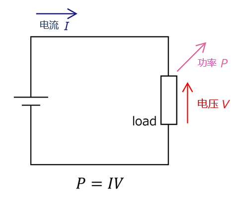
We must begin by understanding electrical power in the first place: the rate at which energy is transferred to or from a component of an electrical circuit.
我们首先需要了解什么是电气功率:电气电路中能量传输到或从一个元件的速率。
In an electrical circuit, the power is equal to the voltage difference across the element times current. The power is measured in watts (1W = 1J/s).
在电气电路中,功率等于元件两端的电压差乘以电流,功率以瓦特为单位测量 (1W = 1J/s)。
V × I V \times I V×I
Electric current
电流
E l e c t r i c P o w e r = V o l t a g e × C u r r e n t P = V × I P = I 2 × R P = V 2 R \begin{aligned} Electric\ Power &= Voltage \times Current \\ P &= V \times I \\ P &= I^{2} \times R \\ P &= \frac{V^{2}}{R} \\ \end{aligned} Electric PowerPPP=Voltage×Current=V×I=I2×R=RV2
These equations are derived from Ohm’s Law, where
V
V
V is the voltage in the circuit,
I
I
I is the current, and
R
R
R is the resistance in the circuit.
这些方程是从欧姆定律推导出来的,其中
V
V
V 是电路中的电压,
I
I
I 是电流,
R
R
R 是电路中的电阻。
V = I × R V = I \times R V=I×R

Figure 1. Measuring AC current is a major component of verifying power generation and dissipation in large loads. Image used courtesy of Canva
Instantaneous Power
瞬时功率
Instantaneous power means the power at any instant of time or the power at any given moment of time and can be written as:
瞬时功率是指任何瞬间的功率或任何给定时刻的功率,可以表示为:
P ( t ) = V ( t ) × I ( t ) P(t) = V(t) \times I(t) P(t)=V(t)×I(t)
In a DC circuit, the power required for voltage
V
V
V to force current
I
I
I through a circuit is equal to
V
V
V times
I
I
I. Similarly, if the instantaneous current is passed through the circuit, the power required at each instant is equal to the value of the voltage at that instant times the current at the same instant. In the practical world, loads are the combination of resistive, inductive, and capacitive elements at the consumer end.
在直流电路中,电压
V
V
V 强制电流
I
I
I 通过电路所需的功率等于
V
V
V 乘以
I
I
I。同样,如果将瞬时电流通过电路,每个瞬时所需的功率等于该瞬时的电压值乘以同一瞬时的电流值。在实际应用中,负载是电阻性、电感性和电容性元件的组合,位于消费端。
Three Types of Loads
三种类型的负载
1. Resistive Load: where
V
V
V and
I
I
I are in phase and the power is always positive like braking resistors, heaters, and light bulbs.
电阻性负载:电压
V
V
V 和电流
I
I
I 同相,功率始终为正,例如制动电阻、加热器和灯泡。
2. Inductive Load: current lags behind voltage like motors, transformers, and inductors.
电感性负载:电流滞后于电压,例如电机、变压器和电感器。
3. Capacitive Load: current leads voltage (few examples of pure capacitive loads).
电容性负载:电流超前于电压(纯电容负载的例子很少)。
The phase-angle difference between the current and voltage has an important effect on the power supplied, as the instantaneous voltage corresponding to any particular instantaneous current depends on the angle between them. Therefore, in alternating current circuits, power cannot usually be obtained simply by multiplying the effective voltages and effective currents as done in the case of DC. The effect on the power of the difference in phase angle between the current and voltage must be taken into account.
电流和电压之间的相位角差对供电功率有重要影响,因为任何特定瞬时电流对应的瞬时电压取决于它们之间的相位角。因此,在交流电路中,功率通常不能像直流电路那样简单地通过有效电压和有效电流的乘积来获得,必须考虑电流和电压相位角差对功率的影响。
Types of Power:
功率的类型:
1. Active Power (kW, MW, GW)
有功功率(千瓦、兆瓦、吉瓦)
2. Reactive Power (kVAR, MVAR)
无功功率(千乏、兆乏)
3. Apparent Power (kVA, MVA)
视在功率(千伏安、兆伏安)

Figure 2 describes the famous analogy to understand the difference between the three powers. The glass filled with water represents the true power, and the frothy form on the top is reactive power, and the sum of active and reactive is apparent power in the analogy.
图 2 描述了一个著名的类比,用于理解这三种功率之间的区别。装满水的玻璃杯代表有功功率,顶部的泡沫代表无功功率,有功功率和无功功率的总和是视在功率。
Active Power or Real Power
有功功率或实际功率
Active power is often called real, true, actual, or useful power. In DC circuits, power is simply the voltage across the load times the current flowing through it because in DC circuits there is no phase angle between the voltage and current, therefore no power factor in DC circuits. In other words, the voltage and current are in phase with each other, meaning the voltage and current start and end at the same time, each peak, and then go to zero at the same time.
有功功率通常被称为实际功率、真实功率、实际功率或有用功率。在直流电路中,功率仅仅是负载两端的电压乘以流过它的电流,因为在直流电路中电压和电流之间没有相位角,因此直流电路中没有功率因数。换句话说,电压和电流彼此同相,意味着电压和电流同时开始和结束,每个峰值,然后同时归零。
In DC circuits
在直流电路中
P = V × I f o r D C c i r c u i t s P = V \times I\ for\ DC\ circuits P=V×I for DC circuits
Whereas in AC circuits, there is a phase angle between voltage and current expressed with the added component of
θ
\theta
θ.
而在交流电路中,电压和电流之间存在相位角,用
θ
\theta
θ 表示。
In a single-phase AC circuit, active power is:
在单相交流电路中,有功功率为:
P = V × I × cos θ P = V \times I \times \cos \theta P=V×I×cosθ
In a three-phase AC circuit:
在三相交流电路中:
P = 3 × V × I × cos θ P = \sqrt{3} \times V \times I \times \cos \theta P=3×V×I×cosθ
In Figure 3, the current and voltage are in phase with each other making
θ
=
0
\theta = 0
θ=0 degree angle at the same time and the positive voltage times positive current generates positive power. When both current and voltage are negative, the power is still positive, therefore in both cases the power is always positive, this is called active power. The power curve will entirely be above the horizontal axis and reflects that all of the work done is positive.
在图 3 中,电流和电压彼此同相,使
θ
=
0
\theta = 0
θ=0 度角在同一时间,正电压乘以正电流产生正功率。当电流和电压均为负值时,功率仍为正,因此在两种情况下,功率始终为正,这被称为有功功率。功率曲线将完全位于水平轴上方,反映出所做的所有工作均为正。
The real power (also called useful power or watt-full power) actually does the real work in the circuit and always flows from source to load or is supplied to the load from the generator all of the time as in Figure 4.
真正的功率(也称为有效功率或有功功率)实际上在电路中做实际的工作,总是从电源流向负载,或者从发电机持续供应给负载,如图 4 所示。
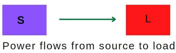
Figure 4. Active power flows from source to load
Features of Active Power:
有功功率的特点:
-
The active power is always positive and does not change its direction, always flows from source to load.
有功功率始终为正,不会改变方向,始终从电源流向负载。 -
Denoted by P P P and measured in watts (kW, MW, GW).
用 P P P 表示,以瓦特(千瓦、兆瓦、吉瓦)为单位进行测量。 -
Measure using a wattmeter.
使用瓦特表进行测量。 -
Active power produces heat, mechanical power, and work.
有功功率产生热量、机械功率和功。
Reactive Power
无功功率
Reactive power occurs in AC circuits when voltage and current are not in phase. Its unit is VAR (volt-ampere reactive). In the real world, loads are a combination of resistive, inductive, and capacitive elements and it is impossible to determine the nature of the load (small/large, domestic/industrial, inductive/capacitive). There are two types of reactance:
无功功率出现在交流电路中,当电压和电流不同相时。其单位是乏尔(VAR)。在现实世界中,负载是电阻性、电感性和电容性元件的组合,无法确定负载的性质(小/大、家用/工业、电感性/电容性)。有两种类型的电抗:
-
Capacitive Reactance (negative)
电容性电抗(负) -
Inductive Reactance (positive)
电感性电抗(正)
The power can be positive and negative. When the power is flowing from source to load then it’s positive, and the power is flowing from load to source then it’s called negative power. In general, reactive power is only defined for AC circuits and continuously bounces back and forth between source and load and is symbolized with the letter Q as in Figure 5.
功率可以是正的,也可以是负的。当功率从电源流向负载时,它是正的;而当功率从负载流向电源时,则被称为负功率。一般来说,无功功率仅针对交流电路定义,它在电源和负载之间持续来回振荡,并用字母 Q 表示,如图 5 所示。
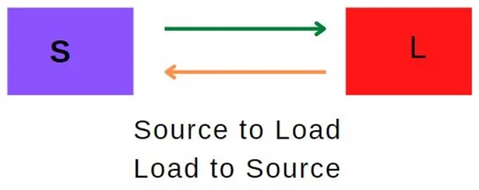
Figure 5. Reactive power flows from source to load and back to the source.
Reactive Power
Q
Q
Q
无功功率
Q
Q
Q
Q = V × I × sin θ Q = V \times I \times \sin \theta Q=V×I×sinθ
Features of Reactive Power:
无功功率的特点:
-
Changes its direction periodically and it is positive as well as negative.
周期性地改变方向,可以是正的也可以是负的。 -
Donated by the letter " Q Q Q " and measured in VAR, KVAR, MVAR.
用字母“ Q Q Q ”表示,以乏尔(VAR)、千乏(KVAR)、兆乏(MVAR)为单位进行测量。 -
Measured using VAR meter.
使用乏尔表进行测量。 -
Transformers and induction motors use reactive power to produce a magnetic field.
变压器和感应电机使用无功功率来产生磁场。
Transformers also need reactive power to generate a magnetic field in the primary coil and induce voltage in the secondary coil. Therefore, if the reactive power supply is not adequate, the transformer will not transform voltages and the motor will not rotate. Synchronous generators also generate or absorb reactive power depending upon DC excitation to its field winding. When the generator is over-excited it generates reactive power and absorbs reactive power when the generator is under-excited.
变压器还需要无功功率来在初级线圈中产生磁场,并在次级线圈中感应电压。因此,如果无功功率供应不足,变压器将无法变换电压,电机将无法旋转。同步发电机也会根据其励磁绕组的直流励磁生成或吸收无功功率。当发电机过励时,它会生成无功功率,而当发电机欠励时,它会吸收无功功率。
Apparent Power
视在功率
This power is the combination of active and reactive power and is expressed in volt-amperes or kilovolt-amperes (kVA).
这种功率是有功功率和无功功率的组合,以伏安或千伏安(kVA)为单位表示。
In fact, most of the loads in our everyday life (electric fan, electric iron, induction motor) are a combination of resistive & inductive loads. The resistive load consumes active power and the inductive load consumes reactive power and the total power derived by the source is the combination of active & reactive power is called apparent power.
事实上,我们日常生活中的大多数负载(电扇、电熨斗、感应电机)是电阻性负载和电感性负载的组合。电阻性负载消耗有功功率,电感性负载消耗无功功率,电源提供的总功率是有功功率和无功功率的组合,称为视在功率。
Apparent Power S S S
视在功率 S S S
S 2 = P 2 + Q 2 S^{2} = P^{2} + Q^{2} S2=P2+Q2
Where
S
S
S is Apparent Power measured in kVA,
Q
Q
Q is Reactive Power in kVAR and
P
P
P is Active Power in kW.
其中
S
S
S 是以千伏安(kVA)为单位的视在功率,
Q
Q
Q 是以千乏(kVAR)为单位的无功功率,
P
P
P 是以千瓦(kW)为单位的有功功率。
Features of Apparent Power:
视在功率的特点:
-
Apparent power is the sum of active and reactive power.
视在功率是有功功率和无功功率的总和。 -
Donated by the letter " S S S ".
用字母“ S S S ”表示。 -
Measured in VA, kVA, and MVA.
以伏安(VA)、千伏安(kVA)和兆伏安(MVA)为单位进行测量。
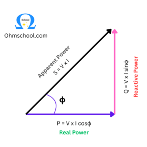
Power Triangle
功率三角形
The relationship between powers can be represented in the form of vectors called the “Power Triangle”. The active power is represented as horizontal whereas reactive power is shown as vertical vector and the apparent power connects the active and reactive vectors. If the angle "
θ
\theta
θ " between active and apparent power increases, the reactive power increases.
功率之间的关系可以用向量表示,称为“功率三角形”。有功功率用水平向量表示,无功功率用垂直向量表示,视在功率连接有功功率和无功功率向量。如果有功功率和视在功率之间的角度“
θ
\theta
θ ”增大,无功功率也会增大。
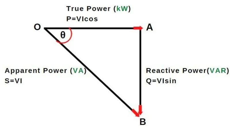
Figure 6. The power triangle describes the relationship between active, reactive, and apparent power
图 6. 功率三角形描述了有功功率、无功功率和视在功率之间的关系
Power Factor
功率因数
The power factor is an important concept in an electrical system and a good power factor determines the design quality and efficient use of the supply in the electrical system. It shows the ratio of the true power to the apparent power and is simply the ratio of active (true) power in watts to apparent power in volt-amperes.
功率因数是电气系统中的一个重要概念,良好的功率因数决定了电气系统中供电的设计质量和有效利用。它表示有功功率与视在功率的比率,即以瓦特为单位的有功功率与以伏安为单位的视在功率的比率。
P o w e r F a c t o r = A c t i v e P o w e r A p p a r e n t P o w e r 功率因数 = 有功功率 视在功率 Power\ Factor = \frac{Active\ Power}{Apparent\ Power} \\[1em] 功率因数 = \frac{有功功率}{视在功率} Power Factor=Apparent PowerActive Power功率因数=视在功率有功功率
A power factor of 1.0 is called “unity power factor” or 100% power factor, which means that the current and voltage are “in phase”. It is impossible to obtain 100% power factor at any point of the power system. In transmission lines, high PF is necessary which reduces transmission losses and is also better for inductive load-like motors to run efficiently and avoid overheating.
功率因数为 1.0 被称为“单位功率因数”或 100% 功率因数,这意味着电流和电压“同相”。在电力系统的任何一点都无法获得 100% 的功率因数。在输电线中,高功率因数是必要的,它可以减少传输损耗,对于像电机这样的电感性负载来说,也有助于高效运行并避免过热。
The question is: what does the power factor actually indicate? Suppose the power factor is 0.8. This means that, out of 100%, the system is consuming 80% of active power and 20% is reactive power. This is the significance of the power factor that indicates the total amount of active power in the system. The power factor is an important term in an AC power system. If the voltage and power of the system are constant, then the power factor is inversely proportional.
问题是:功率因数实际上表示什么?假设功率因数为 0.8。这意味着在 100% 中,系统消耗了 80% 的有功功率,而 20% 是无功功率。这就是功率因数的意义,它表示系统中总的有功功率量。功率因数是交流电力系统中的一个重要术语。如果系统的电压和功率是恒定的,那么功率因数是成反比的。
L i n e C u r r e n t ∝ 1 P o w e r F a c t o r 线路电流 ∝ 1 P F Line\ Current \propto \frac{1}{Power\ Factor}\\[1em] \text{线路电流} \propto \frac{1}{PF} Line Current∝Power Factor1线路电流∝PF1
The expression of three-phase power is written as:
三相功率的表达式为:
P = 3 × V × I × cos θ T h e r e f o r e , I = P 3 × V × cos θ \begin{aligned} P &= \sqrt{3} \times V \times I \times \cos \theta \\ Therefore,\\ I &= \frac{P}{\sqrt{3} \times V \times \cos \theta} \\ \end{aligned} PTherefore,I=3×V×I×cosθ=3×V×cosθP
Here the factors
P
P
P,
3
\sqrt{3}
3,
V
V
V are taken as constants, therefore current is inversely proportional to
cos
θ
\cos \theta
cosθ. i.e.
I
∝
1
/
cos
θ
I \propto {1}/{\cos \theta }
I∝1/cosθ This means that if the power factor of the system is low, the current of the system becomes large.
这里,将
P
P
P、
3
\sqrt{3}
3 和
V
V
V 视为常数,因此电流与
cos
θ
\cos \theta
cosθ 成反比。这意味着如果系统的功率因数较低,系统的电流就会变大
I
∝
1
cos
θ
I \propto \frac{1}{\cos \theta}
I∝cosθ1。
Disadvantages of Low Power Factor in a System
系统中低功率因数的缺点
-
If the power factor of the system is lower, the system’s current becomes large.
如果系统的功率因数较低,系统的电流会变大。 -
Large KVA rating of the equipment: alternators, transformers, and switchgear are rated in KVA as we know that K V A = K W cos θ KVA = \frac{KW}{\cos \theta} KVA=cosθKW, which means that if you need desired power in kW from the machine, the KVA of the machine needs to be higher. Therefore, to increase the current-carrying capacity of the machine, the cross-sectional conducting parts of the machine have to be made larger which makes the machine larger, heavier, and more expensive.
设备的千伏安(KVA)额定值较大:发电机、变压器和开关设备的额定值为千伏安,因为 K V A = K W cos θ KVA = \frac{KW}{\cos \theta} KVA=cosθKW,这意味着如果你需要从机器中获取所需的千瓦(kW)功率,机器的千伏安(KVA)需要更高。因此,为了增加机器的载流能力,机器的导电部分截面积需要增大,这会使机器更大、更重、更昂贵。 -
Greater conductor size: At the low power factor for transmitting the same quantity of power larger cross-section of the conductor is required. This is because, at low power factor conditions, more current is required to fulfill the useful power demand of the consumer.
导体尺寸更大:在低功率因数下传输相同数量的功率时,需要更大截面积的导体。这是因为,在低功率因数条件下,需要更多的电流来满足消费者的有用功率需求。 -
Large copper losses: As we already know that current is inversely proportional to the power factor, therefore if the power factor of the power system is low, the current will increase I ∝ 1 P F I \propto \frac{1}{PF} I∝PF1. The line losses increased by I 2 × R I^{2} \times R I2×R which results in lower efficiency of the system.
铜损较大:正如我们已经知道的,电流与功率因数成反比,因此如果电力系统的功率因数较低,电流会增加 I ∝ 1 P F I \propto \frac{1}{PF} I∝PF1。线路损耗增加 I 2 × R I^{2} \times R I2×R,导致系统效率降低。 -
The low lagging power factor causes a high voltage drop in alternators and transformers.
低滞后功率因数会导致发电机和变压器中出现较大的电压降。
Power Factor Lagging vs Leading
功率因数滞后与超前
In the power network system, reactive power can be increased and decreased using system excitation. If excitation increases, it means flux increases and consequently reactive power will increase. When reactive power increases power factor lags (decreases). The lagging load consumes reactive power and the generator will supply reactive power to the system.
在电力网络系统中,可以通过系统励磁来增加和减少无功功率。如果励磁增加,意味着磁通量增加,因此无功功率也会增加。当无功功率增加时,功率因数滞后(降低)。滞后负载消耗无功功率,发电机将向系统供应无功功率。
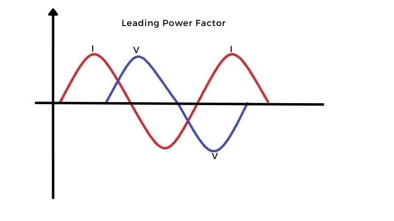
Figure 7. Visualization of ‘leading’ power factor.
Let’s look into another way when the voltage decreases, excitation decreases which means flux decreases and consequently reactive power will decrease, and hence power factor leads (increases). The generator consumes reactive power from the load. This reactive power is used to build the magnetic field required by the generator to work properly. So we can say that over-excited synchronous machine acts as a capacitor and under-excited synchronous machine acts as an inductor.
让我们再看看另一种情况,当电压降低时,励磁也会降低,这意味着磁通量减少,因此无功功率也会减少,从而功率因数超前(增加)。发电机从负载中消耗无功功率。这种无功功率用于建立发电机正常工作所需的磁场。因此,我们可以这样说,过励的同步电机表现为电容器,而欠励的同步电机表现为电感器。
It has become the practice to say that the power factor is lagging when the current lags the supply voltage and leading when the current leads the supply voltage.
通常的做法是说,当电流滞后于供电电压时,功率因数为滞后;当电流超前于供电电压时,功率因数为超前。
Power Factor Effect on a System
功率因数对系统的影响
Active power is useful power that does some actual work in an AC circuit, whereas reactive power is non-useful power that flows back and forth (in both directions from source to load) but produces electric or magnetic flux. Apparent power is the total power in the system and is the combination of active power and reactive power and measured in KVAR. Large industrial types of equipment like transformers are mentioned in KVA. The lower the power factor, the greater the size of the source to generate that power which results in the cost of generation and transmission of the electric energy.
有功功率是有用功率,在交流电路中完成实际工作,而无功功率是非有用功率,它在电源和负载之间来回流动(双向流动),但会产生电场或磁场通量。视在功率是系统中的总功率,是有功功率和无功功率的组合,以千乏(KVAR)为单位进行测量。像变压器这样的大型工业设备以千伏安(KVA)为单位提及。功率因数越低,产生该功率所需的电源尺寸越大,这会导致发电和输电的成本增加。
What is Active, Reactive and Apparent Power
什么是有功功率、无功功率和视在功率
26/07/2025 by ohmschool.com
In electrical engineering, understanding the types of power in an AC circuit is essential. The three key types of power are Active Power, Reactive Power, and Apparent Power. These terms help explain how energy is consumed, stored, and transferred in electrical systems.
在电气工程中,理解交流电路中的功率类型是至关重要的。三种关键的功率类型是有功功率(Active Power)、无功功率(Reactive Power)和视在功率(Apparent Power)。这些术语有助于解释电能系统中能量是如何被消耗、储存和传输的。
What is Active Power? (True or Real Power)
什么是主动功率?(真实功率或实际功率)
Definition:
定义:
Active Power (also known as Real Power or True Power) is the power that is actually consumed or utilized in an AC electrical circuit to perform useful work—such as lighting, heating, or rotating a motor.
有功功率(也称为实际功率或真实功率)是在交流电路中实际被消耗或利用的功率,用于完成有用的工作,例如照明、加热或驱动电机。
-
Measured in: kilowatts (kW) or megawatts (MW)
测量单位: 千瓦(kW)或兆瓦(MW) -
Symbol: P
符号: P P P
Active Power Formula:
有功功率公式:
P = V × I × cos ϕ P = V \times I \times \cos \phi P=V×I×cosϕ
What is Reactive Power?
什么是无功功率?
Definition:
定义:
Reactive Power is the power that flows back and forth between the source and reactive components (inductors and capacitors) in an AC circuit. It does not perform any useful work but is necessary to maintain the electric and magnetic fields in the system.
无功功率是在交流电路中在电源和电抗元件(电感和电容)之间来回流动的功率。它不完成任何有用的工作,但对于维持系统中的电场和磁场是必要的。
-
Measured in: kilovolt-amperes reactive (kVAR) or megavolt-amperes reactive (MVAR)
测量单位: 千乏(kVAR)或兆乏(MVAR) -
Symbol: Q
符号: Q Q Q
Reactive power exists due to the phase difference between voltage and current. This type of power is needed to energize inductive and capacitive loads, such as motors and transformers.
无功功率的存在是由于电压和电流之间的相位差。这种类型的功率用于激励电感性和电容性负载,例如电机和变压器。
Reactive Power Formula:
无功功率公式:
Q = V × I × sin ( ϕ ) Q = V \times I \times \sin(\phi) Q=V×I×sin(ϕ)
What is Apparent Power?
什么是视在功率?
Definition:
定义:
Apparent Power is the total power flowing in the circuit, which is a combination of both Active Power and Reactive Power.
视在功率是电路中流动的总功率,是有功功率和无功功率的组合。
-
Measured in: kilovolt-amperes (kVA) or megavolt-amperes (MVA)
测量单位: 千伏安(kVA)或兆伏安(MVA) -
Symbol: S
符号: S S S
Apparent power represents the total capacity of an electrical system to deliver energy, regardless of whether the power is used for work or just circulating in the system.
视在功率代表了电气系统提供能量的总能力,无论功率是用于做功还是仅仅在系统中循环。
It has been seen that power is consumed only in resistance. A pure inductor and a pure capacitor do not consume any power since in a half cycle whatever power is received from the source by these components, the same power is returned to the source. This power which returns and flows in both directions in the circuit, is called Reactive power. This reactive power does not perform any useful work in the circuit.
人们发现,功率只在电阻中被消耗。纯电感和纯电容不消耗任何功率,因为在半个周期内,这些元件从电源接收的功率与返回到电源的功率相同。这种在电路中双向流动的功率被称为无功功率。这种无功功率在电路中不完成任何有用的工作。
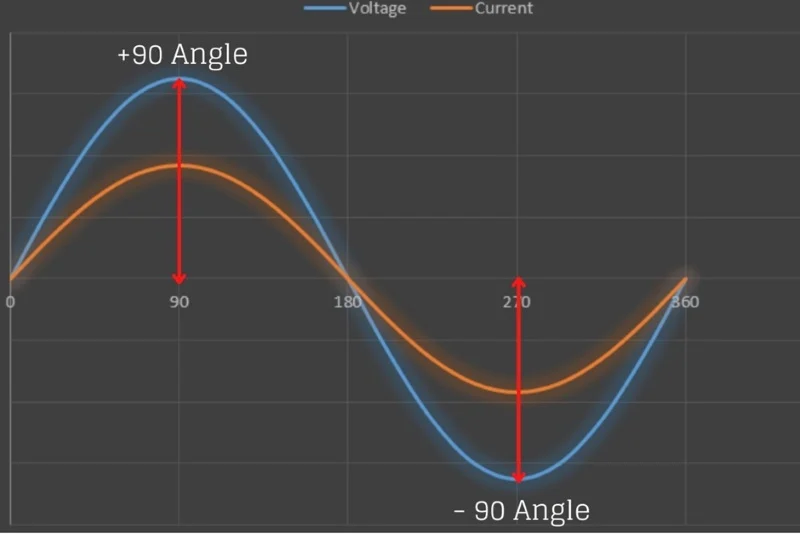
In a purely resistive circuit, the current is in phase with the applied voltage, whereas in a purely inductive and capacitive circuit the current is 90 degrees out of phase, i.e., if the inductive load is connected in the circuit the current lags voltage by 90 degrees and if the capacitive load is connected the current leads the voltage by 90 degrees.
在纯电阻电路中,电流与施加的电压同相,而在纯电感和电容电路中,电流与电压相差 90 度,即如果电路中连接了电感负载,电流滞后于电压 90 度,如果连接了电容负载,电流超前于电压 90 度。

Hence, from all the above discussion, it is concluded that the current in phase with the voltage produces true or active power, whereas, the current 90 degrees out of phase with the voltage contributes to reactive power in the circuit.
因此,从上述所有讨论中可以得出结论,与电压同相的电流产生真实功率或有功功率,而与电压相差 90 度的电流则对电路中的无功功率有贡献。
Therefore,
因此,
-
True power = voltage × \times × current in phase with the voltage
真实功率 = 电压 × \times × 与电压同相的电流 -
Reactive power = voltage × \times × current out of phase with the voltage
无功功率 = 电压 × \times × 与电压不同相的电流
The phasor diagram for an inductive circuit is shown below:
下面显示了一个电感电路的相量图:
Taking voltage
V
V
V as reference, the current
I
I
I lags behind the voltage
V
V
V by an angle
ϕ
\phi
ϕ. The current
I
I
I is divided into two components:
以电压
V
V
V 为参考,电流
I
I
I 落后于电压
V
V
V 一个角度
ϕ
\phi
ϕ。电流
I
I
I 被分为两个分量:
-
I cos ϕ I \cos \phi Icosϕ in phase with the voltage V V V
与电压 V V V 同相的 I cos ϕ I \cos \phi Icosϕ -
I sin ϕ I \sin \phi Isinϕ which is 90 degrees out of phase with the voltage V V V
与电压 V V V 相差 90 度的 I sin ϕ I \sin \phi Isinϕ
Therefore, the following expression shown below gives the active, reactive and apparent power respectively.
因此,下面的表达式分别给出了有功功率、无功功率和视在功率。
-
Active power P = V × I cos ϕ = V I cos ϕ P = V \times I \cos \phi = V I \cos \phi P=V×Icosϕ=VIcosϕ
有功功率 P = V × I cos ϕ = V I cos ϕ P = V \times I \cos \phi = V I \cos \phi P=V×Icosϕ=VIcosϕ -
Reactive power P r P_r Pr or Q = V × I sin ϕ = V I sin ϕ Q = V \times I \sin \phi = V I \sin \phi Q=V×Isinϕ=VIsinϕ
无功功率 P r P_r Pr 或 Q = V × I sin ϕ = V I sin ϕ Q = V \times I \sin \phi = V I \sin \phi Q=V×Isinϕ=VIsinϕ -
Apparent power P a P_a Pa or S = V × I = V I S = V \times I = VI S=V×I=VI
视在功率 P a P_a Pa 或 S = V × I = V I S = V \times I = VI S=V×I=VI
Components of Current
电流的分量
Active component of the current
电流的有功分量
The current component, which is in phase with the circuit voltage and contributes to the active or true power of the circuit, is called an active component or watt-full component or in-phase component of the current.
与电路电压同相并且对电路的有功功率或真实功率有贡献的电流分量被称为有功分量,或瓦特满量分量,或电流的同相分量。
Reactive component of the current
电流的无功分量
The current component, which is in quadrature or 90 degrees out of phase to the circuit voltage and contributes to the reactive power of the circuit, is called a reactive component of the current.
与电路电压相差 90 度或正交并且对电路的无功功率有贡献的电流分量被称为电流的无功分量。
Final Thoughts
总结
-
Active Power is useful power that runs your appliances.
有功功率是有用的功率,用于驱动您的电器。 -
Reactive Power is needed for maintaining the voltage levels.
无功功率用于维持电压水平。 -
Apparent Power is the total power your system must handle.
视在功率是您的系统必须处理的总功率。
Understanding the difference between active, reactive, and apparent power helps in designing efficient electrical systems, improving power factor, and optimizing load capacity.
理解有功功率、无功功率和视在功率之间的区别有助于设计高效的电气系统,提高功率因数,并优化负载能力。
True, Reactive, and Apparent Power | Power Factor
有功功率、无功功率与视在功率 | 功率因数
True Power
有功功率
The actual amount of power being used, or dissipated, in a circuit is called true power, and it is measured in watts (symbolized by the capital letter
P
P
P, as always).
电路中实际使用或损耗的功率称为有功功率,其计量单位为瓦特(符号始终为大写字母
P
P
P)。
Reactive Power
无功功率
We know that reactive loads such as inductors and capacitors dissipate zero power, yet the fact that they drop voltage and draw current gives the deceptive impression that they actually do dissipate power.
我们知道,电感器和电容器等无功负载的功率损耗为零,但它们会产生电压降并汲取电流,这容易让人误以为它们确实消耗了功率。
This “phantom power” is called reactive power, and it is measured in a unit called Volt-Amps-Reactive (VAR), rather than watts.
这种“虚功功率”被称为无功功率,其计量单位为乏(Volt-Amps-Reactive, VAR),而非瓦特。
The mathematical symbol for reactive power is (unfortunately) the capital letter
Q
Q
Q.
无功功率的数学符号(遗憾的是)为大写字母
Q
Q
Q。
Apparent Power
视在功率
The combination of reactive power and true power is called apparent power, and it is the product of a circuit’s voltage and current, without reference to phase angle.
无功功率与有功功率的合成称为视在功率,它是电路电压与电流的乘积,与相位角无关。
Apparent power is measured in the unit of Volt-Amps (VA) and is symbolized by the capital letter
S
S
S.
视在功率的计量单位为伏安(Volt-Amps, VA),符号为大写字母
S
S
S。
Calculating for Reactive, True, or Apparent Power
无功功率、有功功率与视在功率的计算
As a rule, true power is a function of a circuit’s dissipative elements, usually resistances (
R
R
R). Reactive power is a function of a circuit’s reactance (
X
X
X). Apparent power is a function of a circuit’s total impedance (
Z
Z
Z).
通常,有功功率是电路耗能元件(通常为电阻
R
R
R)的函数,无功功率是电路电抗
X
X
X 的函数,视在功率是电路总阻抗
Z
Z
Z 的函数。
Since we’re dealing with scalar quantities for power calculation, any complex starting quantities such as voltage (
V
V
V), current (
I
I
I), and impedance must be represented by their polar magnitudes, not by real or imaginary rectangular components.
由于功率计算涉及标量,所有初始复数量(如电压
V
V
V、电流
I
I
I 和阻抗)均需以极坐标幅值表示,而非实部或虚部的直角坐标分量。
For instance, if I’m calculating true power from current and resistance, I must use the polar magnitude for current, and not merely the “real” or “imaginary” portion of the current.
例如,若通过电流和电阻计算有功功率,必须使用电流的极坐标幅值,而非仅采用电流的“实部”或“虚部”。
If I’m calculating apparent power from voltage and impedance, both of these formerly complex quantities must be reduced to their polar magnitudes for the scalar arithmetic.
若通过电压和阻抗计算视在功率,这两个原复数量均需转换为极坐标幅值,再进行标量运算。
Equations Using Scalar Quantities
基于标量的计算公式
There are several power equations relating the three types of power to resistance, reactance, and impedance (all using scalar quantities):
以下是三种功率与电阻、电抗和阻抗相关的计算公式(均采用标量):
-
有功功率(瓦特)
T r u e P o w e r ( W a t t s ) = P = I 2 R = V 2 R True\ Power\ (Watts) = P = I^2 R = \frac{V^2}{R} True Power (Watts)=P=I2R=RV2 -
无功功率(乏,VAR)
R e a c t i v e P o w e r ( V o l t − A m p s − R e a c t i v e , V A R ) = Q = I 2 X = V 2 X Reactive\ Power\ (Volt-Amps-Reactive, VAR) = Q = I^2 X = \frac{V^2}{X} Reactive Power (Volt−Amps−Reactive,VAR)=Q=I2X=XV2 -
视在功率(伏安,VA)
A p p a r e n t P o w e r ( V o l t − A m p s , V A ) = S = I 2 Z = V 2 Z = I V Apparent\ Power\ (Volt-Amps, VA) = S = I^2 Z = \frac{V^2}{Z} = I V Apparent Power (Volt−Amps,VA)=S=I2Z=ZV2=IV
Please note that there are two equations each for the calculation of true and reactive power. There are three equations available for the calculation of apparent power,
S
=
I
V
S = I V
S=IV being useful only for that purpose.
请注意,有功功率和无功功率各有两个计算公式,视在功率有三个计算公式,其中
S
=
I
V
S = I V
S=IV 仅适用于视在功率的计算。
Example Power Calculations
功率计算示例
Examine the following circuits and see how these three types of power interrelate for: a purely resistive load, a purely reactive load, and a resistive/reactive load.
请分析以下三种电路,了解三种功率的相互关系:纯电阻负载电路、纯无功负载电路以及电阻-无功混合负载电路。
Resistive Load Only
纯电阻负载
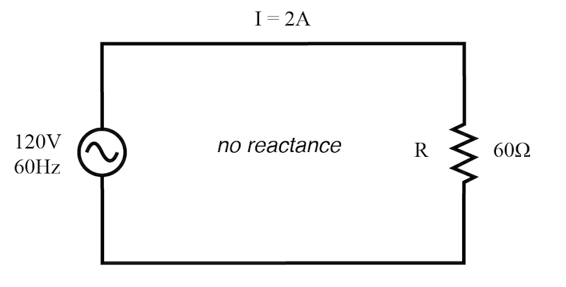
True power, reactive power, and apparent power for a purely resistive load.
纯电阻负载的有功功率、无功功率与视在功率。
I
=
2
A
,
120
V
,
60
H
z
,
无电抗
,
R
=
60
Ω
I = 2 \, A,120 \, V,\ 60 \, Hz,\ 无电抗,\ R = 60 \, \Omega
I=2A,120V, 60Hz, 无电抗, R=60Ω
-
有功功率
T r u e P o w e r = P = I 2 R = 2 2 × 60 = 240 W True\ Power = P = I^2 R = 2^2 \times 60 = 240 \, W True Power=P=I2R=22×60=240W -
无功功率
R e a c t i v e P o w e r = Q = I 2 X = 2 2 × 0 = 0 V A R Reactive\ Power = Q = I^2 X = 2^2 \times 0 = 0 \, VAR Reactive Power=Q=I2X=22×0=0VAR -
视在功率
A p p a r e n t P o w e r = S = I 2 Z = 2 2 × 60 = 240 V A Apparent\ Power = S = I^2 Z = 2^2 \times 60 = 240 \, VA Apparent Power=S=I2Z=22×60=240VA
Reactive Load Only
纯无功负载
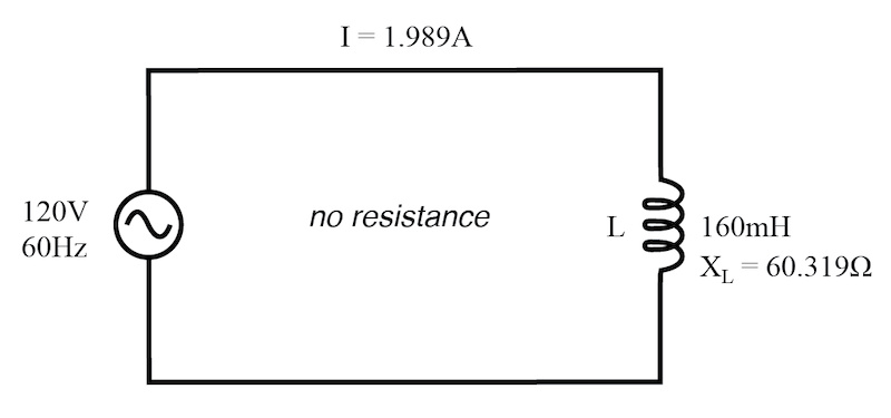
True power, reactive power, and apparent power for a purely reactive load.
纯无功负载的有功功率、无功功率与视在功率。
I
=
1.989
A
,
120
V
,
60
H
z
,
无电阻
,
X
=
60.319
Ω
(
160
m
H
)
I = 1.989 \, A,120 \, V,\ 60 \, Hz,\ 无电阻,\ X = 60.319 \, \Omega\ (160 \, mH)
I=1.989A,120V, 60Hz, 无电阻, X=60.319Ω (160mH)
-
有功功率
T r u e P o w e r = P = I 2 R = 1.98 9 2 × 0 = 0 W True\ Power = P = I^2 R = 1.989^2 \times 0 = 0 \, W True Power=P=I2R=1.9892×0=0W -
无功功率
R e a c t i v e P o w e r = Q = I 2 X = 1.98 9 2 × 60.319 ≈ 238.73 V A R Reactive\ Power = Q = I^2 X = 1.989^2 \times 60.319 \approx 238.73 \, VAR Reactive Power=Q=I2X=1.9892×60.319≈238.73VAR -
视在功率
A p p a r e n t P o w e r = S = I 2 Z = 1.98 9 2 × 60.319 ≈ 238.73 V A Apparent\ Power = S = I^2 Z = 1.989^2 \times 60.319 \approx 238.73 \, VA Apparent Power=S=I2Z=1.9892×60.319≈238.73VA
Resistive/Reactive Load
电阻-无功混合负载
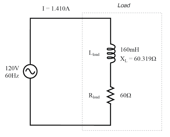
True power, reactive power, and apparent power for a resistive/reactive load.
电阻-无功混合负载的有功功率、无功功率与视在功率。
I
=
1.410
A
,
120
V
,
60
H
z
,
R
l
o
a
d
=
60
Ω
,
X
=
60.319
Ω
(
160
m
H
)
I = 1.410 \, A,120 \, V,\ 60 \, Hz,\ R_{load} = 60 \, \Omega,\ X = 60.319 \, \Omega\ (160 \, mH)
I=1.410A,120V, 60Hz, Rload=60Ω, X=60.319Ω (160mH)
-
总阻抗
Z = R 2 + X 2 = 6 0 2 + 60.31 9 2 ≈ 85.158 Ω Z = \sqrt{R^2 + X^2} = \sqrt{60^2 + 60.319^2} \approx 85.158 \, \Omega Z=R2+X2=602+60.3192≈85.158Ω -
有功功率
T r u e P o w e r = P = I 2 R = 1.41 0 2 × 60 ≈ 119.364 W True\ Power = P = I^2 R = 1.410^2 \times 60 \approx 119.364 \, W True Power=P=I2R=1.4102×60≈119.364W -
无功功率
R e a c t i v e P o w e r = Q = I 2 X = 1.41 0 2 × 60.319 ≈ 119.998 V A R Reactive\ Power = Q = I^2 X = 1.410^2 \times 60.319 \approx 119.998 \, VAR Reactive Power=Q=I2X=1.4102×60.319≈119.998VAR -
视在功率
A p p a r e n t P o w e r = S = I 2 Z = 1.41 0 2 × 85.158 ≈ 169.256 V A Apparent\ Power = S = I^2 Z = 1.410^2 \times 85.158 \approx 169.256 \, VA Apparent Power=S=I2Z=1.4102×85.158≈169.256VA
The Power Triangle
功率三角形
These three types of power—true, reactive, and apparent—relate to one another in trigonometric form. We call this the power triangle.
有功功率、无功功率和视在功率三者呈三角函数关系,这种关系被称为功率三角形。
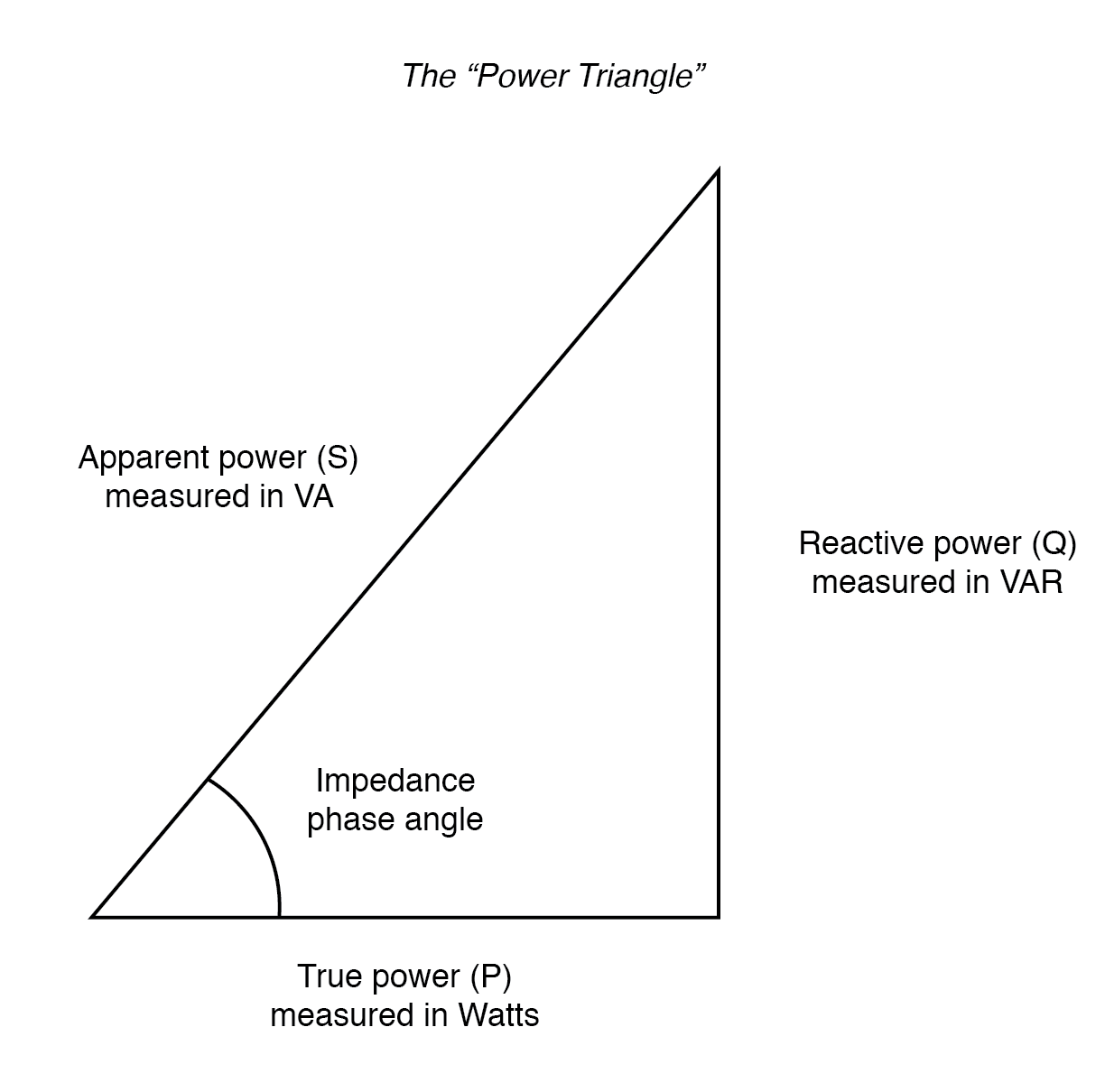
Power triangle relating apparent power to true power and reactive power.
功率三角形展示了视在功率与有功功率、无功功率的关系。
| 功率类型 | 符号 | 单位 | 三角形对应边 |
|---|---|---|---|
| Apparent Power | S S S | Volt-Amps (VA) | 斜边(hypotenuse) |
| True Power | P P P | Watts (W) | 邻边(adjacent) |
| Reactive Power | Q Q Q | Volt-Amps-Reactive (VAR) | 对边(opposite) |
Using the laws of trigonometry, we can solve for the length of any side (amount of any type of power), given the lengths of the other two sides, or the length of one side and an angle. The opposite angle to the reactive power (
Q
Q
Q) is equal to the circuit’s impedance (
Z
Z
Z) phase angle (
θ
\theta
θ), and the trigonometric relationships are as follows:
根据三角定律,已知任意两边的长度(或任意一边的长度与一个角度),可求解第三边的长度(即任意一种功率的数值)。无功功率
Q
Q
Q 对应的角等于电路阻抗
Z
Z
Z 的相位角
θ
\theta
θ,三角函数关系如下:
cos
θ
=
P
S
,
sin
θ
=
Q
S
,
tan
θ
=
Q
P
\cos\theta = \frac{P}{S}, \quad \sin\theta = \frac{Q}{S}, \quad \tan\theta = \frac{Q}{P}
cosθ=SP,sinθ=SQ,tanθ=PQ
cos
θ
=
有功功率
视在功率
,
sin
θ
=
无功功率
视在功率
,
tan
θ
=
无功功率
有功功率
\cos\theta = \frac{有功功率}{视在功率}, \quad \sin\theta = \frac{无功功率}{视在功率}, \quad \tan\theta = \frac{无功功率}{有功功率}
cosθ=视在功率有功功率,sinθ=视在功率无功功率,tanθ=有功功率无功功率
Review
总结
-
The power dissipated by a load is referred to as true power. True power is symbolized by the letter P P P and is measured in the unit of Watts (W).
负载消耗的功率称为有功功率,符号为 P P P,单位为瓦特(W)。 -
Power merely absorbed and returned in load due to its reactive properties is referred to as reactive power. Reactive power is symbolized by the letter Q Q Q and is measured in the unit of Volt-Amps-Reactive (VAR).
负载因无功特性而吸收并回馈的功率称为无功功率,符号为 Q Q Q,单位为乏(VAR)。 -
Total power in an AC circuit, both dissipated and absorbed/returned, is referred to as apparent power. Apparent power is symbolized by the letter S S S and is measured in the unit of Volt-Amps (VA).
交流电路中,消耗的功率与吸收/回馈的功率之和称为视在功率,符号为 S S S,单位为伏安(VA)。 -
These three types of power are trigonometrically related to one another. In a right triangle, P P P = adjacent length, Q Q Q = opposite length, and S S S = hypotenuse length. The opposite angle is equal to the circuit’s impedance ( Z Z Z) phase angle ( θ \theta θ).
三种功率呈三角函数关系:在直角三角形中,有功功率 P P P 为邻边,无功功率 Q Q Q 为对边,视在功率 S S S 为斜边,对边对应的角度等于电路阻抗 Z Z Z 的相位角 θ \theta θ。
无功功率的本质解析与电路特性
技成培训 发布于 2021-03-31 15:14
在交流电相关应用场景中,“无功功率”是一个频繁出现的术语,但对其物理意义与电路作用的深入理解仍存在局限。本文将从功率基础定义出发,结合电感、电容元件的能量特性,系统阐述无功功率的内涵、表现形式及工程意义。
无功功率并非“无用的功率”,而是一类不涉及能量消耗、仅用于电路储能元件与电源之间能量交换的功率形式。它与有功功率存在明确区分,差异体现在能量转换的方式上。
在正弦交流电路中,无功功率的产生与电感、电容两类储能元件直接相关。因此,在深入分析无功功率之前,需先明确功率的基本定义,以及交流电路中电感、电容元件的功率变化规律。
一、相关功率的定义
无论是热能、电能还是机械能,所有涉及能量变化(做功)的过程,都需要通过功率进行量化分析。功率表征能量变化(消耗或转换)的快慢,这一物理量的本质可通过类比理解:若将能量变化类比为跑步的位移,功率则对应跑步的速度——速度越快,相同时间内的位移(能量变化量)越大。
若以能量变化量为纵轴、时间为横轴绘制曲线(如图 1-1 所示),则该曲线上任意一点的切线斜率,即为对应时刻的功率值。
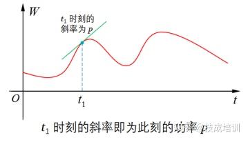
图 1-1 能量变化曲线与功率的关系
由图 1-1 可见,随着时间推移,能量变化曲线的斜率随时间动态变化,表明功率随时间呈周期性波动,这种随时间变化的功率称为瞬时功率。
在电路中,瞬时功率的数学定义为某一时刻电压瞬时值与电流瞬时值的乘积,表达式为:
p
=
u
i
p = ui
p=ui
其中,
p
p
p、
u
u
u、
i
i
i 分别表示瞬时功率、瞬时电压、瞬时电流(均用小写字母标注),单位为瓦特(W)。瞬时功率的物理意义可通过实例说明:
t
=
0
t=0
t=0 时刻瞬时功率
p
=
10
W
p=10\ \text{W}
p=10 W,表示该时刻电能的变化速度为
10
J/s
10\ \text{J/s}
10 J/s;
t
=
t
1
t=t_1
t=t1 时刻瞬时功率
p
=
25
W
p=25\ \text{W}
p=25 W,表示此时电能的变化速度为
25
J/s
25\ \text{J/s}
25 J/s。
工程应用中,电能计量仪表显示的功率、家用电器铭牌标注的功率均为平均功率。平均功率是瞬时功率在一个周期内的时间平均值,用大写字母 P P P 表示,单位同样为瓦特(W)。
根据功率与能量的本质关系,电能总量
W
W
W 与平均功率
P
P
P、时间
t
t
t 的关系为:
W
=
P
t
W = Pt
W=Pt
该式与“跑步总位移 = 平均速度 × 时间”的逻辑一致。若以瞬时功率为纵轴、时间为横轴绘制曲线,則该曲线与时间轴围成的面积即为对应时间段内的能量变化量(如图 1-2 所示)。
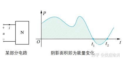
图 1-2 瞬时功率曲线与能量变化量的关系
由图 1-2 可知,电路端口的瞬时功率曲线与时间轴围成的面积存在正负之分:
- 在 0 ∼ t 1 0 \sim t_1 0∼t1 时间段内,瞬时功率为正值,曲线与时间轴围成的面积为正,表明该部分电路从外部吸收能量;
- 在 t 1 ∼ t 2 t_1 \sim t_2 t1∼t2 时间段内,瞬时功率为负值,曲线与时间轴围成的面积为负,表明该部分电路向外部释放能量。
平均功率的计算方法为:将某一时间段内所有能量变化量(吸收为正、释放为负)求和,再除以该时间段的时长,即:
P
=
W
总
t
P = \frac{W_{\text{总}}}{t}
P=tW总
这一计算逻辑与“平均速度 = 总位移 ÷ 总时间”(向前位移为正、向后位移为负)完全一致。
基于上述对瞬时功率与平均功率的定义,下文将进一步分析正弦交流电路中电感元件和电容元件的功率特性。
二、交流电路中电感元件和电容元件的功率
在正弦交流电路中,理想电感元件与理想电容元件均属于储能元件,其特性为非耗能性——在任意完整周期内,这类元件从电源吸收的总能量与释放的总能量相等,总能量变化量为零。这一特性的物理本质可通过以下功率分析进行说明。
1、交流电路中电感元件的功率
在正弦交流电路中,理想电感元件的电压相位超前电流相位 9 0 ∘ 90^\circ 90∘( π / 2 \pi/2 π/2 弧度),其电压、电流的波形关系如图 1-3 所示(绿色曲线为电压 u u u,蓝色曲线为电流 i i i)。
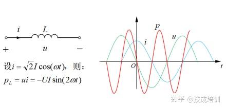
图 1-3 电感元件的电压、电流及瞬时功率波形
电压相位超前电流相位 9 0 ∘ 90^\circ 90∘ 的直观判断方法:
- 时间轴上,电压波形先达到最大值,电流波形后达到最大值,两者峰值出现的时间差对应相位差 9 0 ∘ 90^\circ 90∘;
- 电压波形先经过正斜率过零点(从负向变为正向的零点),电流波形后经过正斜率过零点,两者过零点的时间差对应相位差 9 0 ∘ 90^\circ 90∘。
根据瞬时功率的定义 p = u i p = ui p=ui,结合电压与电流的相位关系,可推导得出电感元件的瞬时功率波形(图 1-3 中红色曲线)。该波形的数学推导需基于三角函数运算,具体过程可参考正弦交流电路分析相关资料。
将电感元件的瞬时功率波形单独提取(如图 1-4 所示),可见其瞬时功率按正弦规律变化,是一个周期性物理量,周期为电压或电流周期的 1 / 2 1/2 1/2。
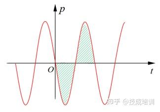
图 1-4 电感元件的瞬时功率单独波形
结合瞬时功率与能量变化的关系(曲线与时间轴围成的面积为能量),从图 1-4 可观察到:
- 在瞬时功率的正半周期,功率为正值,电感元件从电源吸收能量,转化为磁场能储存;
- 在瞬时功率的负半周期,功率为负值,电感元件将储存的磁场能释放回电源;
- 由于波形的对称性,正半周期与负半周期围成的面积大小相等、符号相反,表明一个周期内电感元件吸收的总能量与释放的总能量相等,总能量变化量为零。
这一特性体现了电感元件的非耗能本质:电感元件仅在电源与自身之间进行磁场能与电能的相互转换,不将电能转化为热能、光能等不可逆形式消耗(与电阻元件的耗能特性形成鲜明对比),这种能量交换特性称为储能特性。
基于瞬时功率的周期性与对称性,电感元件的平均功率可通过一个周期内的能量变化量计算:
P
L
=
1
T
∫
0
T
p
L
(
t
)
d
t
P_L = \frac{1}{T} \int_0^T p_L(t) dt
PL=T1∫0TpL(t)dt
由于一个周期内总能量变化量
∫
0
T
p
L
(
t
)
d
t
=
0
\int_0^T p_L(t) dt = 0
∫0TpL(t)dt=0,因此电感元件的平均功率
P
L
=
0
P_L = 0
PL=0,其物理意义如图 1-5 所示。
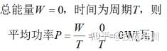
图 1-5 电感元件的平均功率为零的物理意义
2、交流电路中电容元件的功率
在正弦交流电路中,理想电容元件的电流相位超前电压相位 9 0 ∘ 90^\circ 90∘( π / 2 \pi/2 π/2 弧度),其电压、电流的波形关系如图 1-6 所示(绿色曲线为电压 u u u,蓝色曲线为电流 i i i)。
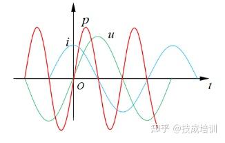
图 1-6 电容元件的电压、电流及瞬时功率波形
根据瞬时功率的定义 p = u i p = ui p=ui,结合电容元件电压与电流的相位关系,可推导得出其瞬时功率波形(图 1-6 中红色曲线)。该波形同样为周期性正弦曲线,周期为电压或电流周期的 1 / 2 1/2 1/2。
与电感元件类似,电容元件的瞬时功率波形具有对称性:正半周期内电容吸收电能转化为电场能储存,负半周期内释放电场能回电源,一个周期内吸收与释放的总能量相等,总能量变化量为零。因此,电容元件的平均功率 P C = 0 P_C = 0 PC=0。
由于电感元件和电容元件的平均功率均为零,而工程计量与应用中常用平均功率描述能量消耗,因此需要引入一个新的物理量来表征这类储能元件与电源之间的能量交换强度——这一物理量即为无功功率。
三、无功功率的定义与物理意义
为量化电感元件、电容元件与电源之间的能量交换规模,工程上将这类储能元件的瞬时功率最大值定义为无功功率,用字母 Q Q Q 表示,单位为乏(var)。
以电容元件为例,其无功功率的物理意义如图 1-7 所示:瞬时功率波形的峰值即为无功功率的数值,它表征储能元件与电源之间能量交换的最大速率(与功率表征能量变化快慢的本质一致)。
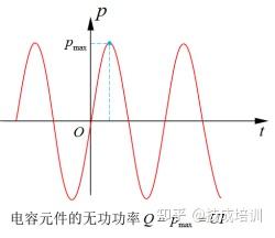
图 1-7 电容元件的无功功率(瞬时功率最大值)
在数值上,无功功率等于储能元件两端电压的有效值与通过元件电流的有效值的乘积,即:
Q
=
U
I
Q = UI
Q=UI
该公式的数学推导基于正弦交流电路中电压、电流的瞬时表达式(
u
=
U
m
sin
(
ω
t
)
u = U_m \sin(\omega t)
u=Umsin(ωt)、
i
=
I
m
sin
(
ω
t
±
9
0
∘
)
i = I_m \sin(\omega t \pm 90^\circ)
i=Imsin(ωt±90∘)),通过三角函数运算可证明瞬时功率的最大值为
U
m
I
m
/
2
=
U
I
U_m I_m / 2 = UI
UmIm/2=UI(其中
U
=
U
m
/
2
U = U_m / \sqrt{2}
U=Um/2、
I
=
I
m
/
2
I = I_m / \sqrt{2}
I=Im/2 分别为电压、电流的有效值),具体推导过程可参考正弦交流电路功率分析相关理论。
电感元件的无功功率同样满足 Q = U I Q = UI Q=UI,其物理意义与电容元件一致,均表征元件与电源之间能量交换的最大速率。
从物理本质来看,无功功率具有“功率的形式、非耗能的特性”:
- 其“功率属性”体现在表征能量变化的速率;
- 其“非耗能特性”体现在仅涉及能量的交换与储存,不产生不可逆的能量损耗。
这一特性也解释了“无功”的含义——无能量消耗,但存在能量交换。
补充:电感与电容的无功功率互补特性
当电感元件与电容元件串联时,若施加相同的正弦交流电压,两者的瞬时功率波形呈现反向互补关系(如图 1-8 所示):当电感元件吸收能量(瞬时功率为正)时,电容元件释放能量(瞬时功率为负);反之,当电感元件释放能量时,电容元件吸收能量。这种互补特性使得电感与电容之间可实现部分能量的内部交换,从而减少与电源之间的能量交换规模。
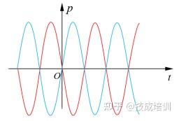
图 1-8 串联电感与电容的瞬时功率互补波形
多元件电路的有功功率与无功功率
当电路中同时存在电阻、电感、电容三类元件时,端口的总瞬时功率为三类元件瞬时功率的叠加(如图 1-9 所示)。为明确区分不同元件的功率特性,工程上作出如下定义:
- 电阻元件消耗的平均功率称为有功功率,其数值等于端口电压有效值、电流有效值与电压电流相位差余弦值的乘积,即 P = U I cos φ P = UI \cos\varphi P=UIcosφ( φ \varphi φ 为电压与电流的相位差);
- 电感与电容元件的总无功功率称为电路的总无功功率,其数值等于端口电压有效值、电流有效值与电压电流相位差正弦值的乘积,即 Q = U I sin φ Q = UI \sin\varphi Q=UIsinφ。
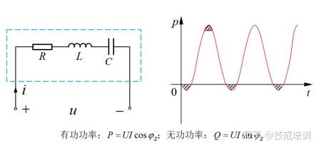
图 1-9 混合电路的总瞬时功率波形(红色为总功率,蓝色为电阻功率,绿色为储能元件总功率)
有功功率 P = U I cos φ P = UI \cos\varphi P=UIcosφ 与无功功率 Q = U I sin φ Q = UI \sin\varphi Q=UIsinφ 的推导过程
设正弦交流电路端口的电压、电流瞬时表达式为:
u
=
U
m
sin
(
ω
t
)
i
=
I
m
sin
(
ω
t
−
φ
)
u = U_m \sin(\omega t)\\ i = I_m \sin(\omega t - \varphi)
u=Umsin(ωt)i=Imsin(ωt−φ)
其中,
φ
\varphi
φ 为电压超前电流的相位差(电阻、电感、电容混合电路中,
φ
\varphi
φ 的取值范围为
−
9
0
∘
∼
9
0
∘
-90^\circ \sim 90^\circ
−90∘∼90∘)。
1:瞬时功率
根据瞬时功率定义
p
=
u
i
p = ui
p=ui,代入电压、电流瞬时值:
p
=
U
m
sin
(
ω
t
)
⋅
I
m
sin
(
ω
t
−
φ
)
=
U
m
I
m
2
[
cos
φ
−
cos
(
2
ω
t
−
φ
)
]
\begin{align*} p &= U_m \sin(\omega t) \cdot I_m \sin(\omega t - \varphi) \\ &= \frac{U_m I_m}{2} \left[ \cos\varphi - \cos(2\omega t - \varphi) \right] \end{align*}
p=Umsin(ωt)⋅Imsin(ωt−φ)=2UmIm[cosφ−cos(2ωt−φ)]
该推导利用了三角函数积化和差公式:
sin
A
sin
B
=
1
2
[
cos
(
A
−
B
)
−
cos
(
A
+
B
)
]
\sin A \sin B = \frac{1}{2}[\cos(A-B) - \cos(A+B)]
sinAsinB=21[cos(A−B)−cos(A+B)]。
2:有功功率(平均功率)
平均功率为瞬时功率在一个周期内的时间平均值:
P
=
1
T
∫
0
T
p
d
t
=
1
T
∫
0
T
U
m
I
m
2
[
cos
φ
−
cos
(
2
ω
t
−
φ
)
]
d
t
P = \frac{1}{T} \int_0^T p dt = \frac{1}{T} \int_0^T \frac{U_m I_m}{2} \left[ \cos\varphi - \cos(2\omega t - \varphi) \right] dt
P=T1∫0Tpdt=T1∫0T2UmIm[cosφ−cos(2ωt−φ)]dt
由于余弦函数
cos
(
2
ω
t
−
φ
)
\cos(2\omega t - \varphi)
cos(2ωt−φ) 在一个周期内的积分值为零(正负半周期对称抵消),因此:
P
=
U
m
I
m
2
cos
φ
P = \frac{U_m I_m}{2} \cos\varphi
P=2UmImcosφ
代入电压、电流有效值与最大值的关系
U
=
U
m
2
U = \frac{U_m}{\sqrt{2}}
U=2Um、
I
=
I
m
2
I = \frac{I_m}{\sqrt{2}}
I=2Im(即
U
m
I
m
=
2
U
I
U_m I_m = 2UI
UmIm=2UI),可得:
P
=
U
I
cos
φ
P = UI \cos\varphi
P=UIcosφ
3:无功功率
瞬时功率表达式可拆分为两部分:
p
=
U
I
cos
φ
−
U
I
cos
(
2
ω
t
−
φ
)
p = UI \cos\varphi - UI \cos(2\omega t - \varphi)
p=UIcosφ−UIcos(2ωt−φ)
其中,
U
I
cos
φ
UI \cos\varphi
UIcosφ 为恒定分量(对应电阻元件的平均功率),
U
I
cos
(
2
ω
t
−
φ
)
UI \cos(2\omega t - \varphi)
UIcos(2ωt−φ) 为交变分量(对应电感、电容元件的能量交换功率)。
交变分量的最大值为
U
I
UI
UI,但由于电感与电容的相位差影响,实际参与能量交换的最大速率需考虑相位差
φ
\varphi
φ。结合三角函数展开:
U
I
cos
(
2
ω
t
−
φ
)
=
U
I
cos
φ
cos
2
ω
t
+
U
I
sin
φ
sin
2
ω
t
UI \cos(2\omega t - \varphi) = UI \cos\varphi \cos2\omega t + UI \sin\varphi \sin2\omega t
UIcos(2ωt−φ)=UIcosφcos2ωt+UIsinφsin2ωt
其中,与电阻功率相关的恒定分量已单独分离,剩余交变分量的最大值为
U
I
sin
φ
UI \sin\varphi
UIsinφ,该值即为电路的总无功功率:
Q
=
U
I
sin
φ
Q = UI \sin\varphi
Q=UIsinφ
当电路中仅含电阻时,
φ
=
0
∘
\varphi = 0^\circ
φ=0∘,
sin
φ
=
0
\sin\varphi = 0
sinφ=0,
Q
=
0
Q = 0
Q=0(无无功功率);
当电路中仅含电感时,
φ
=
9
0
∘
\varphi = 90^\circ
φ=90∘,
sin
φ
=
1
\sin\varphi = 1
sinφ=1,
Q
=
U
I
Q = UI
Q=UI;
当电路中仅含电容时,
φ
=
−
9
0
∘
\varphi = -90^\circ
φ=−90∘,
sin
φ
=
−
1
\sin\varphi = -1
sinφ=−1,
Q
=
−
U
I
Q = -UI
Q=−UI(负号表示无功功率的方向与电感相反)。
交流电的功率:有功功率、无功功率及视在功率
1. 概述
1.1 定义与研究背景
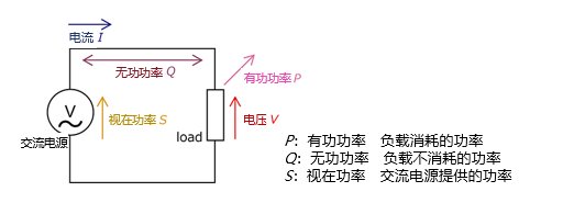
在交流电路分析及工程应用中,有功功率、无功功率和视在功率是描述能量传输与转换特性的关键参数。三者的量化关系与电压、电流的相位差密切相关,其比值衍生出功率因数这一重要指标,直接影响电能利用效率与电力系统稳定性。掌握这些参数的定义、计算方法及工程特性,是电力系统设计、设备选型、能效优化的重要基础。
1.2 参数基本特征
- 有功功率:对应负载实际消耗并用于做功的电能,与电阻元件相关,能量转换不可逆;
- 无功功率:储能元件与电源之间往返交换的能量,不直接转化为有用功,但为电力设备正常运行所必需;
- 视在功率:表征交流电源的总容量,是有功功率与无功功率的矢量合成结果;
- 功率因数:有功功率与视在功率的比值,反映电能利用效率,取值范围为 0 ∼ 1 0 \sim 1 0∼1(正弦电路)。
2. 交直流电路的功率差异
2.1 直流电路的功率特性
直流电路中,电压
V
V
V 与电流
I
I
I 的幅值和方向恒定,不存在相位差,功率计算仅为电压与电流的乘积,即:
P
=
I
V
P = IV
P=IV
该功率全部转化为有用功(如热能、机械能),单位为瓦特(
W
W
W)。
2.2 交流电路的功率特性
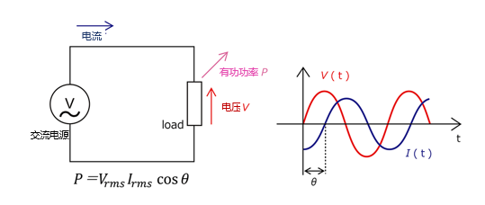
交流电路中,电压与电流随时间按正弦规律变化( u = U m sin ω t u = U_m\sin\omega t u=Umsinωt, i = I m sin ( ω t − θ ) i = I_m\sin(\omega t - \theta) i=Imsin(ωt−θ)),且因电感、电容等储能元件的存在,二者产生相位差 θ \theta θ。这种周期性变化与相位差异导致能量传输存在“消耗”与“交换”两种形式,因此需通过有功功率、无功功率、视在功率三个参数分别表征。
3. 功率的定义、数学表达与特性
3.1 有功功率( P P P)
3.1.1 定义与物理意义
有功功率的单位为瓦特( W W W),是电路中电阻元件消耗的有效电能,对应实际做功的能量转换过程(如电能转化为热能、光能、机械能)。有功功率仅与电路的电阻分量相关,因电阻不会使电压与电流产生相位差,能量转换过程不可逆。日常表述中,未特别说明的“功率”通常特指有功功率。
3.1.2 数学表达式与推导
瞬时功率
p
p
p 定义为电压瞬时值
u
u
u 与电流瞬时值
i
i
i 的乘积:
p
=
u
i
p = ui
p=ui
设正弦交流电路中电压
u
=
U
m
sin
ω
t
u = U_m\sin\omega t
u=Umsinωt,电流
i
=
I
m
sin
(
ω
t
−
θ
)
i = I_m\sin(\omega t - \theta)
i=Imsin(ωt−θ)(
θ
\theta
θ 为电流滞后电压的相位差),代入得:
p
=
U
m
I
m
sin
ω
t
⋅
sin
(
ω
t
−
θ
)
p = U_mI_m\sin\omega t \cdot \sin(\omega t - \theta)
p=UmImsinωt⋅sin(ωt−θ)
利用三角函数积化和差公式
sin
A
sin
B
=
1
2
[
cos
(
A
−
B
)
−
cos
(
A
+
B
)
]
\sin A\sin B = \frac{1}{2}[\cos(A-B) - \cos(A+B)]
sinAsinB=21[cos(A−B)−cos(A+B)] 化简:
p
=
U
m
I
m
2
[
cos
θ
−
cos
(
2
ω
t
−
θ
)
]
p = \frac{U_mI_m}{2}[\cos\theta - \cos(2\omega t - \theta)]
p=2UmIm[cosθ−cos(2ωt−θ)]
有功功率为瞬时功率在一个周期
T
T
T 内的平均值,因余弦项
cos
(
2
ω
t
−
θ
)
\cos(2\omega t - \theta)
cos(2ωt−θ) 在一个周期内积分值为 0,最终得:
P
=
U
I
cos
θ
P = UI\cos\theta
P=UIcosθ
其中,
U
=
U
m
2
U = \frac{U_m}{\sqrt{2}}
U=2Um、
I
=
I
m
2
I = \frac{I_m}{\sqrt{2}}
I=2Im 分别为电压、电流的有效值,
cos
θ
\cos\theta
cosθ 为功率因数。
3.1.3 计算步骤
- 测量电压有效值 U rms U_{\text{rms}} Urms 与电流有效值 I rms I_{\text{rms}} Irms,确保数据对应电路实际工况;
- 通过示波器等设备测量电压与电流的相位差 θ \theta θ(观测波形过零点或峰值的时间偏差);
- 代入公式 P = U rms I rms cos θ P = U_{\text{rms}}I_{\text{rms}}\cos\theta P=UrmsIrmscosθ 计算有功功率。
3.1.4 工程意义
有功功率的准确计算与优化,可提高电源效率(家用电器领域)、优化生产工艺(工业领域)、保障供电稳定性(可再生能源领域),同时减少电压降与电流波动,实现电力系统负载均衡分配。
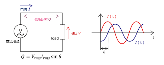
3.2 无功功率( Q Q Q)
3.2.1 定义与物理意义
无功功率的单位为乏( VAR \text{VAR} VAR),是表征电感、电容等储能元件与电源之间能量交换快慢的物理量,定义为储能元件瞬时功率的最大值。
无功功率的“无功”并非指“无用”,而是指能量仅在储能元件与电源之间往返交换,不转化为不可逆的有用功(如热能)。电机、变压器等设备需借助无功功率建立磁场,维持正常运行。直流电路中无储能元件的周期性能量交换,故不存在无功功率。
3.2.2 产生机制
无功功率由电压与电流的相位差( θ ≠ 0 ∘ \theta \neq 0^\circ θ=0∘)产生,源于非阻性负载的电抗特性:
- 电感元件通过磁场存储电能,电流相位滞后电压 9 0 ∘ 90^\circ 90∘,产生感性无功(规定 Q > 0 Q > 0 Q>0);
- 电容元件通过电场存储电能,电流相位超前电压 9 0 ∘ 90^\circ 90∘,产生容性无功(规定 Q < 0 Q < 0 Q<0)。
3.2.3 数学表达式与推导
由瞬时功率化简式
p
=
U
I
cos
θ
−
U
I
cos
(
2
ω
t
−
θ
)
p = UI\cos\theta - UI\cos(2\omega t - \theta)
p=UIcosθ−UIcos(2ωt−θ) 可知,瞬时功率的交变分量(频率为
2
ω
2\omega
2ω)反映储能元件与电源的能量交换过程,其幅值即为无功功率:
Q
=
U
I
sin
θ
Q = UI\sin\theta
Q=UIsinθ
其中,
U
U
U 为电压有效值,
I
I
I 为电流有效值,
θ
\theta
θ 为电压与电流的相位差。
3.2.4 单一储能元件的无功功率特性
- 电感元件:设电感电压 u L = U L m cos ω t u_L = U_{Lm}\cos\omega t uL=ULmcosωt,电流 i L = I L m sin ω t i_L = I_{Lm}\sin\omega t iL=ILmsinωt,则瞬时功率 p L = U L I L sin 2 ω t p_L = U_LI_L\sin2\omega t pL=ULILsin2ωt,平均功率 P L = 0 P_L = 0 PL=0,无功功率 Q L = U L I L Q_L = U_LI_L QL=ULIL(感性无功, Q L > 0 Q_L > 0 QL>0);
- 电容元件:设电容电压 u C = U C m sin ω t u_C = U_{Cm}\sin\omega t uC=UCmsinωt,电流 i C = I C m cos ω t i_C = I_{Cm}\cos\omega t iC=ICmcosωt,则瞬时功率 p C = U C I C sin 2 ω t p_C = U_CI_C\sin2\omega t pC=UCICsin2ωt,平均功率 P C = 0 P_C = 0 PC=0,无功功率 Q C = − U C I C Q_C = -U_CI_C QC=−UCIC(容性无功, Q C < 0 Q_C < 0 QC<0)。
3.2.5 互补特性与工程意义
当电感元件与电容元件串联时,两者的瞬时功率波形呈现反向互补关系:电感吸收能量时电容释放能量,反之亦然,这种特性可减少与电源的能量交换规模。
无功功率虽不直接做功,但会增加电力传输过程中的电流幅值,导致线路损耗增大、设备容量利用率下降。精准控制无功功率(如通过电容补偿感性无功)可提高电力系统稳定性,降低额外损耗,提升电能传输效率。
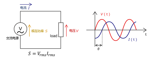
3.3 视在功率( S S S)
3.3.1 定义与物理意义
视在功率的单位为伏安( VA \text{VA} VA),是交流电源输出的总功率,表征电源的容量能力,数值上等于电压有效值与电流有效值的乘积。
视在功率是有功功率与无功功率的矢量和,反映电路中总能量的传输规模,是电力设备(如变压器、发电机)容量标注的依据。
3.3.2 数学表达式
S
=
U
I
S = UI
S=UI
结合有功功率与无功功率的表达式,三者满足矢量勾股关系:
S
=
P
2
+
Q
2
S = \sqrt{P^2 + Q^2}
S=P2+Q2
3.3.3 工程意义
视在功率的计算与优化在电力系统设计中至关重要:
- 设备容量规划:电源设备(如变压器)的额定容量需按视在功率选型,以满足有功功率输出与无功功率交换的双重需求;
- 电网负载分析:视在功率增大意味着电源负载加重,需通过无功补偿等手段控制其增长,避免设备过载;
- 电能质量评估:视在功率与有功功率的比值(功率因数)直接反映电能利用效率。
4. 三大功率的关系
4.1 数学关联
4.1.1 基本表达式
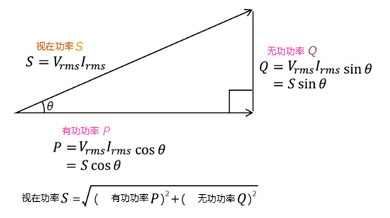
- 有功功率: P = U I cos θ = S cos θ P = UI\cos\theta = S\cos\theta P=UIcosθ=Scosθ
- 无功功率: Q = U I sin θ = S sin θ Q = UI\sin\theta = S\sin\theta Q=UIsinθ=Ssinθ
- 视在功率: S = U I = P 2 + Q 2 S = UI = \sqrt{P^2 + Q^2} S=UI=P2+Q2
4.1.2 三角函数关系
由
cos
2
θ
+
sin
2
θ
=
1
\cos^2\theta + \sin^2\theta = 1
cos2θ+sin2θ=1,可推导:
(
P
S
)
2
+
(
Q
S
)
2
=
1
\left(\frac{P}{S}\right)^2 + \left(\frac{Q}{S}\right)^2 = 1
(SP)2+(SQ)2=1
表明有功功率与无功功率是视在功率在不同相位方向上的分量:
cos
θ
\cos\theta
cosθ 反映同相位分量占比(能量消耗),
sin
θ
\sin\theta
sinθ 反映反相位分量占比(能量交换)。
4.2 矢量表征(功率三角形)
4.2.1 构成要素
功率三角形是三者关系的直观可视化工具,直角三角形的三边对应:
- 水平边(实轴):有功功率 P P P(能量消耗分量);
- 垂直边(虚轴):无功功率 Q Q Q(能量交换分量);
- 斜边:视在功率 S S S(总功率矢量);
- 夹角 θ \theta θ:电压与电流的相位差,也是视在功率与有功功率的夹角。
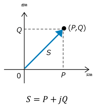
4.2.2 复数表示
在复平面中,视在功率可表示为复数形式:
S
=
P
+
j
Q
S = P + jQ
S=P+jQ
其中,
j
j
j 为虚数单位,实部为有功功率,虚部为无功功率,模值为视在功率的大小。
4.2.3 应用价值
通过功率三角形可快速分析相位差对功率分配的影响:
- θ \theta θ 减小(功率因数提高):有功功率占比增大,无功功率占比减小,电能利用效率提升;
- θ \theta θ 增大(功率因数降低):无功功率占比增大,视在功率同步增大,电力系统损耗增加。
5. 功率因数( cos θ \cos\theta cosθ)
5.1 定义与物理意义
功率因数是有功功率与视在功率的比值,即:
cos
θ
=
P
S
\cos\theta = \frac{P}{S}
cosθ=SP
取值范围为
0
∼
1
0 \sim 1
0∼1(正弦电路),是评估电能利用效率的重要指标。
功率因数越接近 1 1 1,表明无功功率占比越小,电能转化为有用功的比例越高;功率因数过低会导致电网电流增大,增加线路损耗与设备负担,造成电力资源浪费。
5.2 计算方法
5.2.1 基础公式法
直接利用定义式 cos θ = P S \cos\theta = \frac{P}{S} cosθ=SP,结合 S = U I S = UI S=UI 或 S = P 2 + Q 2 S = \sqrt{P^2 + Q^2} S=P2+Q2 计算。
5.2.2 阻抗关联式
在 RL 串联电路中,功率因数等于电阻
R
R
R 与阻抗
Z
Z
Z 的比值:
cos
θ
=
R
Z
\cos\theta = \frac{R}{Z}
cosθ=ZR
其中,阻抗
Z
=
R
2
+
(
2
π
f
L
)
2
Z = \sqrt{R^2 + (2\pi fL)^2}
Z=R2+(2πfL)2(
L
L
L 为电感,
f
f
f 为频率)。
5.2.3 三相电路计算
三相电路中,视在功率
S
=
3
U
L
I
L
S = \sqrt{3}U_LI_L
S=3ULIL(
U
L
U_L
UL 为线电压,
I
L
I_L
IL 为线电流),功率因数:
cos
θ
=
P
3
U
L
I
L
\cos\theta = \frac{P}{\sqrt{3}U_LI_L}
cosθ=3ULILP
5.3 工程测量方法
| 测量方法 | 设备 | 适用场景 | 优势 | 局限性 |
|---|---|---|---|---|
| 功率因数表法 | 指针/数字式功率因数表 | 工频交流电路、简单负载(电机、照明)实时抽检 | 操作简便、成本低 | 仅支持工频、无法监测谐波,精度较低 |
| 多功能电力仪表法 | 集成式电力监测仪 | 工业配电系统、连续运行设备长期监测 | 自动计算、支持数据存储与远程传输 | 需匹配电压/电流量程,不适用于高频电路 |
| 间接计算法 | 电压表+电流表+功率表 | 实验室调试、无专用仪表时临时测量 | 设备通用性强,适用于特殊电压/频率场景 | 需手动计算,效率低,易引入人为误差 |
| 宽频带功率分析仪法 | 谐波功率分析仪 | 含变频器、整流器的谐波负载电路(光伏、变频设备) | 可区分基波/总功率因数,谐波适应性强 | 设备成本高,操作复杂度较高 |
5.4 测量误差修正
- 量程匹配:选择量程为被测值 1.2 ∼ 1.5 1.2 \sim 1.5 1.2∼1.5 倍的仪表,避免量程不足或过大导致失真;
- 接线规范:单相电路按“电压并联、电流串联”接线,三相电路区分线/相电压、电流的对应关系;
- 谐波修正:含非线性负载时,选用支持傅里叶变换的分析仪,分别测量基波与总功率因数;
- 环境屏蔽:远离强电磁干扰源,使用屏蔽线并单端接地,减少信号耦合失真;
- 负载稳定:测量前确保负载连续运行 10 ∼ 15 10 \sim 15 10∼15 分钟,避免启停或波动导致的误差。
5.5 改善方法与工程效果
- 电容补偿:在感性负载端并联电容器,抵消感性无功功率,适用于负载集中的工业场景;
- 功率因数校正装置:通过电力电子技术自动调节电路相位,实时优化功率因数;
- 负载优化:合理分配负载运行时间,避免设备空载或轻载运行,从源头减少无功功率产生。
改善后可实现:电能利用效率提升 5 % ∼ 30 % 5\% \sim 30\% 5%∼30%,线路损耗降低 10 % ∼ 40 % 10\% \sim 40\% 10%∼40%,电力设备使用寿命延长,同时减少电网电压波动。
6. 典型电路功率计算示例
6.1 纯电阻电路(白炽灯、电炉)
- 特性: θ = 0 ∘ \theta = 0^\circ θ=0∘, cos θ = 1 \cos\theta = 1 cosθ=1, Q = 0 Q = 0 Q=0
- 计算:已知单相电路
U
=
220
V
U = 220\ \text{V}
U=220 V,
I
=
5
A
I = 5\ \text{A}
I=5 A
P = 220 V × 5 A × 1 = 1100 W P = 220\ \text{V} \times 5\ \text{A} \times 1 = 1100\ \text{W} P=220 V×5 A×1=1100 W
Q = 220 V × 5 A × 0 = 0 VAR Q = 220\ \text{V} \times 5\ \text{A} \times 0 = 0\ \text{VAR} Q=220 V×5 A×0=0 VAR
S = 220 V × 5 A = 1100 VA S = 220\ \text{V} \times 5\ \text{A} = 1100\ \text{VA} S=220 V×5 A=1100 VA
6.2 纯电感电路(空载变压器)
- 特性: θ = 9 0 ∘ \theta = 90^\circ θ=90∘, cos θ = 0 \cos\theta = 0 cosθ=0, P = 0 P = 0 P=0
- 计算:已知单相电路
U
=
380
V
U = 380\ \text{V}
U=380 V,
I
=
2
A
I = 2\ \text{A}
I=2 A
P = 380 V × 2 A × 0 = 0 W P = 380\ \text{V} \times 2\ \text{A} \times 0 = 0\ \text{W} P=380 V×2 A×0=0 W
Q = 380 V × 2 A × 1 = 760 VAR Q = 380\ \text{V} \times 2\ \text{A} \times 1 = 760\ \text{VAR} Q=380 V×2 A×1=760 VAR
S = 380 V × 2 A = 760 VA S = 380\ \text{V} \times 2\ \text{A} = 760\ \text{VA} S=380 V×2 A=760 VA
6.3 纯电容电路(补偿电容器)
- 特性: θ = − 9 0 ∘ \theta = -90^\circ θ=−90∘, cos θ = 0 \cos\theta = 0 cosθ=0, P = 0 P = 0 P=0
- 计算:已知单相电路
U
=
220
V
U = 220\ \text{V}
U=220 V,
I
=
1.5
A
I = 1.5\ \text{A}
I=1.5 A
P = 220 V × 1.5 A × 0 = 0 W P = 220\ \text{V} \times 1.5\ \text{A} \times 0 = 0\ \text{W} P=220 V×1.5 A×0=0 W
Q = 220 V × 1.5 A × ( − 1 ) = − 330 VAR Q = 220\ \text{V} \times 1.5\ \text{A} \times (-1) = -330\ \text{VAR} Q=220 V×1.5 A×(−1)=−330 VAR
S = 220 V × 1.5 A = 330 VA S = 220\ \text{V} \times 1.5\ \text{A} = 330\ \text{VA} S=220 V×1.5 A=330 VA
6.4 三相电机(对称负载)
- 计算:已知
U
L
=
380
V
U_L = 380\ \text{V}
UL=380 V,
I
L
=
10
A
I_L = 10\ \text{A}
IL=10 A,
cos
θ
=
0.85
\cos\theta = 0.85
cosθ=0.85
S = 3 × 380 V × 10 A ≈ 6582 VA S = \sqrt{3} \times 380\ \text{V} \times 10\ \text{A} \approx 6582\ \text{VA} S=3×380 V×10 A≈6582 VA
P = 3 × 380 V × 10 A × 0.85 ≈ 5595 W P = \sqrt{3} \times 380\ \text{V} \times 10\ \text{A} \times 0.85 \approx 5595\ \text{W} P=3×380 V×10 A×0.85≈5595 W
Q = 3 × 380 V × 10 A × 1 − 0.8 5 2 ≈ 3470 VAR Q = \sqrt{3} \times 380\ \text{V} \times 10\ \text{A} \times \sqrt{1 - 0.85^2} \approx 3470\ \text{VAR} Q=3×380 V×10 A×1−0.852≈3470 VAR
6.5 基础参数计算实例
实例 1:功率三角形法
已知
U
rms
=
100
V
U_{\text{rms}} = 100\ \text{V}
Urms=100 V,
I
rms
=
10
A
I_{\text{rms}} = 10\ \text{A}
Irms=10 A,
P
=
800
W
P = 800\ \text{W}
P=800 W,
Q
=
600
VAR
Q = 600\ \text{VAR}
Q=600 VAR,则:
S
=
100
V
×
10
A
=
1000
VA
cos
θ
=
800
W
1000
VA
=
0.8
\begin{aligned}S &= 100\ \text{V} \times 10\ \text{A} &=& 1000\ \text{VA}\\ \cos\theta &=\frac{800\ \text{W}}{1000\ \text{VA}} &=& 0.8\end{aligned}
Scosθ=100 V×10 A=1000 VA800 W==1000 VA0.8
实例 2:RL 电路法
已知 R = 50 Ω R = 50\ \Omega R=50 Ω, L = 0.1 H L = 0.1\ \text{H} L=0.1 H, U = 100 V U = 100\ \text{V} U=100 V, f = 50 Hz f = 50\ \text{Hz} f=50 Hz,则:
- 感抗 X L = 2 π f L = 2 × 3.14 × 50 × 0.1 ≈ 31.4 Ω X_L = 2\pi fL = 2 \times 3.14 \times 50 \times 0.1 \approx 31.4\ \Omega XL=2πfL=2×3.14×50×0.1≈31.4 Ω;
- 阻抗 Z = R 2 + X L 2 = 5 0 2 + 31. 4 2 ≈ 59.03 Ω Z = \sqrt{R^2 + X_L^2} = \sqrt{50^2 + 31.4^2} \approx 59.03\ \Omega Z=R2+XL2=502+31.42≈59.03 Ω;
- 功率因数 cos θ = R Z = 50 59.03 ≈ 0.847 \cos\theta = \frac{R}{Z} = \frac{50}{59.03} \approx 0.847 cosθ=ZR=59.0350≈0.847。
7. 公式汇总
7.1 基本参数定义
| 参数名称 | 符号 | 单位 | 定义式/换算关系 |
|---|---|---|---|
| 电压有效值 | U U U | V \text{V} V | U = U m 2 U = \frac{U_m}{\sqrt{2}} U=2Um; U = 1 T ∫ 0 T u 2 ( t ) d t U = \sqrt{\frac{1}{T}\int_0^T u^2(t)dt} U=T1∫0Tu2(t)dt |
| 电流有效值 | I I I | A \text{A} A | I = I m 2 I = \frac{I_m}{\sqrt{2}} I=2Im; I = 1 T ∫ 0 T i 2 ( t ) d t I = \sqrt{\frac{1}{T}\int_0^T i^2(t)dt} I=T1∫0Ti2(t)dt |
| 相位差 | θ \theta θ | ∘ / rad ^\circ/\text{rad} ∘/rad | 1 rad ≈ 57. 3 ∘ 1\ \text{rad} \approx 57.3^\circ 1 rad≈57.3∘ |
| 功率因数 | cos θ \cos\theta cosθ | - | cos θ = P S = R Z \cos\theta = \frac{P}{S} = \frac{R}{Z} cosθ=SP=ZR |
7.2 单相交流电路功率公式
| 功率类型 | 公式 | 衍生公式 |
|---|---|---|
| 有功功率 P P P | P = U I cos θ P = UI\cos\theta P=UIcosθ | P = 1 T ∫ 0 T u i d t P = \frac{1}{T}\int_0^T ui dt P=T1∫0Tuidt |
| 无功功率 Q Q Q | Q = U I sin θ Q = UI\sin\theta Q=UIsinθ | Q = S 2 − P 2 Q = \sqrt{S^2 - P^2} Q=S2−P2 |
| 视在功率 S S S | S = U I S = UI S=UI | S = P 2 + Q 2 S = \sqrt{P^2 + Q^2} S=P2+Q2 |
7.3 三相交流电路功率公式
| 功率类型 | 线电压/线电流公式 | 相电压/相电流公式 |
|---|---|---|
| 有功功率 P P P | P = 3 U L I L cos θ P = \sqrt{3}U_LI_L\cos\theta P=3ULILcosθ | P = 3 U P I P cos θ P = 3U_PI_P\cos\theta P=3UPIPcosθ |
| 无功功率 Q Q Q | Q = 3 U L I L sin θ Q = \sqrt{3}U_LI_L\sin\theta Q=3ULILsinθ | Q = 3 U P I P sin θ Q = 3U_PI_P\sin\theta Q=3UPIPsinθ |
| 视在功率 S S S | S = 3 U L I L S = \sqrt{3}U_LI_L S=3ULIL | S = 3 U P I P S = 3U_PI_P S=3UPIP |
7.4 无功补偿量计算
当需将功率因数从
cos
θ
1
\cos\theta_1
cosθ1 提升至
cos
θ
2
\cos\theta_2
cosθ2 时,所需补偿电容的无功功率:
Q
C
=
P
(
tan
θ
1
−
tan
θ
2
)
Q_C = P(\tan\theta_1 - \tan\theta_2)
QC=P(tanθ1−tanθ2)
其中,
P
P
P 为电路总有功功率,
tan
θ
=
sin
θ
cos
θ
\tan\theta = \frac{\sin\theta}{\cos\theta}
tanθ=cosθsinθ。
7.5 非正弦电路说明
含谐波的变频电路中,仅瞬时功率积分法可准确计算有功功率:
P
=
1
T
∫
0
T
u
(
t
)
i
(
t
)
d
t
P = \frac{1}{T}\int_0^T u(t)i(t)dt
P=T1∫0Tu(t)i(t)dt
无功功率分为位移无功(基波相位差引起)与畸变无功(谐波引起),需通过宽频带分析仪测量。
8. 非正弦交流电路的功率特性(补充拓展)
8.1 非正弦电路的产生与特点
非正弦交流电路是指电压或电流波形不满足正弦规律的电路,其产生源于两类场景:
- 非正弦电源激励:如方波发生器、锯齿波电源、变频器输出等;
- 非线性负载作用:如整流器、变频器、电弧炉等非线性元件,会使正弦电源输出的电流产生畸变,形成非正弦电流。
非正弦波形可通过傅里叶级数分解为基波(频率与电源频率一致)和一系列谐波(频率为基波的整数倍,如 3 次、5 次谐波等),即:
f
(
t
)
=
A
0
+
∑
n
=
1
∞
A
n
sin
(
n
ω
t
+
φ
n
)
f(t) = A_0 + \sum_{n=1}^{\infty} A_n\sin(n\omega t + \varphi_n)
f(t)=A0+n=1∑∞Ansin(nωt+φn)
其中,
A
0
A_0
A0 为直流分量(非正弦电路中可能存在),
A
n
A_n
An 为第
n
n
n 次谐波的幅值,
φ
n
\varphi_n
φn 为第
n
n
n 次谐波的初相位,
ω
\omega
ω 为基波角频率。
8.2 非正弦电路的功率计算原则
非正弦电路的功率计算遵循“谐波独立作用原理”:总功率等于各次谐波单独作用时产生的功率之和,不同谐波之间的交叉乘积在一个周期内积分值为 0,不产生有功功率。
8.2.1 有功功率
总有功功率为直流分量的功率与各次谐波有功功率之和:
P
=
P
0
+
∑
n
=
1
∞
P
n
=
U
0
I
0
+
∑
n
=
1
∞
U
n
I
n
cos
θ
n
P = P_0 + \sum_{n=1}^{\infty} P_n = U_0I_0 + \sum_{n=1}^{\infty} U_nI_n\cos\theta_n
P=P0+n=1∑∞Pn=U0I0+n=1∑∞UnIncosθn
其中,
U
0
U_0
U0、
I
0
I_0
I0 分别为电压、电流的直流分量,
U
n
U_n
Un、
I
n
I_n
In 分别为第
n
n
n 次谐波的电压、电流有效值,
θ
n
\theta_n
θn 为第
n
n
n 次谐波电压与电流的相位差。
8.2.2 无功功率
总无功功率为各次谐波无功功率的代数和(需考虑谐波的正负特性):
Q
=
∑
n
=
1
∞
Q
n
=
∑
n
=
1
∞
U
n
I
n
sin
θ
n
Q = \sum_{n=1}^{\infty} Q_n = \sum_{n=1}^{\infty} U_nI_n\sin\theta_n
Q=n=1∑∞Qn=n=1∑∞UnInsinθn
非正弦电路中,无功功率分为“位移无功功率”(基波及各次谐波的相位差引起)和“畸变无功功率”(谐波本身导致的功率损耗),后者无法通过传统电容补偿消除,需专用滤波装置处理。
8.2.3 视在功率
总视在功率为电压总有效值与电流总有效值的乘积:
S
=
U
I
S = UI
S=UI
其中,电压总有效值
U
=
U
0
2
+
∑
n
=
1
∞
U
n
2
U = \sqrt{U_0^2 + \sum_{n=1}^{\infty} U_n^2}
U=U02+∑n=1∞Un2,电流总有效值
I
=
I
0
2
+
∑
n
=
1
∞
I
n
2
I = \sqrt{I_0^2 + \sum_{n=1}^{\infty} I_n^2}
I=I02+∑n=1∞In2。
需注意:非正弦电路中
P
2
+
Q
2
≠
S
\sqrt{P^2 + Q^2} \neq S
P2+Q2=S,两者的差值反映畸变无功功率的影响,因此引入“畸变功率
D
D
D”表征这一差异:
D
=
S
2
−
P
2
−
Q
2
D = \sqrt{S^2 - P^2 - Q^2}
D=S2−P2−Q2
8.3 非正弦电路的功率因数
非正弦电路的功率因数(总功率因数)仍定义为总有功功率与总视在功率的比值:
cos
θ
总
=
P
S
\cos\theta_{\text{总}} = \frac{P}{S}
cosθ总=SP
其数值受两方面影响:
- 各次谐波的位移功率因数( cos θ n \cos\theta_n cosθn);
- 谐波含量(畸变率):谐波含量越高,畸变功率越大,总功率因数越低。
例如,含 3 次谐波的电路中,若基波功率因数为 0.9,谐波畸变率为 30%,总功率因数可能降至 0.85 以下。
8.4 工程应用注意事项
- 谐波抑制:通过加装无源滤波器、有源电力滤波器(APF)等设备,降低谐波含量,减少畸变无功功率;
- 设备选型:非正弦电路中的电力设备(如变压器、电缆)需按总视在功率选型,同时考虑谐波损耗导致的额外温升;
- 功率测量:需选用支持宽频带测量的功率分析仪,避免传统工频仪表因无法识别谐波导致的测量误差。
9. 功率测量的工程实践与常见问题
9.1 测量仪器的选型依据
| 测量场景 | 要求 | 推荐仪器 | 关键参数 |
|---|---|---|---|
| 家用/普通工频电路(照明、家电) | 低成本、易操作 | 数字万用表(带功率档)、指针式功率因数表 | 测量范围: 0 ∼ 220 V 0 \sim 220\ \text{V} 0∼220 V、 0 ∼ 10 A 0 \sim 10\ \text{A} 0∼10 A,精度 ± 2 % \pm 2\% ±2% |
| 工业工频电路(电机、水泵) | 连续监测、数据记录 | 多功能电力仪表 | 支持三相测量,精度 ± 0.5 % \pm 0.5\% ±0.5%,带 RS485 通讯 |
| 谐波负载电路(变频器、光伏逆变器) | 宽频带、谐波分析 | 宽频带功率分析仪 | 测量频率范围 0 ∼ 1 MHz 0 \sim 1\ \text{MHz} 0∼1 MHz,谐波分析次数 ≥ 50 \geq 50 ≥50 次 |
| 实验室高精度测试 | 高分辨率、实时波形 | 示波器+功率探头 | 采样率 ≥ 100 MSa/s \geq 100\ \text{MSa/s} ≥100 MSa/s,功率测量精度 ± 0.1 % \pm 0.1\% ±0.1% |
9.2 常见测量误差来源与修正方法
9.2.1 接线错误导致的误差
- 问题表现:单相电路中电流互感器二次侧开路、三相电路中线电压与相电流错配,导致功率计算值偏大或偏小;
- 修正方法:严格遵循“电压并联、电流串联”原则,三相电路需确保电压端子与电流端子一一对应,接线后进行空载校验(负载为零时功率应接近 0)。
9.2.2 仪器量程不匹配导致的误差
- 问题表现:被测功率远小于仪器量程时,分辨率不足;被测功率超过量程时,数据饱和失真;
- 修正方法:根据被测负载的额定电压、电流估算视在功率,选择量程为估算值 1.2 ∼ 1.5 1.2 \sim 1.5 1.2∼1.5 倍的仪器,对于可变负载(如电机),选用自动量程仪器。
9.2.3 电磁干扰导致的误差
- 问题表现:工业现场的变频器、电焊机等设备产生强电磁辐射,导致测量数据波动;
- 修正方法:使用屏蔽电缆传输信号,仪器接地端单独接地(避免共地干扰),将测量仪器远离干扰源(距离 ≥ 1 m \geq 1\ \text{m} ≥1 m)。
9.2.4 负载不稳定导致的误差
- 问题表现:负载启停、波动时,电压、电流瞬时变化,导致平均功率测量值偏差;
- 修正方法:测量前让负载连续运行 10 ∼ 15 10 \sim 15 10∼15 分钟,待工况稳定后再记录数据,对于周期性波动负载,延长测量周期(如测量 3 个周期取平均值)。
9.3 工程中的功率优化案例
案例 1:工业车间感性负载的无功补偿
- 背景:某车间有 10 台感应电机(总功率 500 kW 500\ \text{kW} 500 kW),运行时功率因数为 0.75 0.75 0.75,导致电网电流过大,线路损耗增加;
- 方案:在车间配电房并联一组自愈式并联电容器(总补偿容量 350 kVAR 350\ \text{kVAR} 350 kVAR),通过无功补偿控制器自动投切;
- 效果:功率因数提升至 0.95 0.95 0.95,线路电流从 800 A 800\ \text{A} 800 A 降至 630 A 630\ \text{A} 630 A,每月减少线路损耗 1.2 1.2 1.2 万度,电力公司力率电费减免 20 % 20\% 20%。
案例 2:变频器谐波治理与功率优化
- 背景:某工厂变频器输出侧电流谐波畸变率为 28 % 28\% 28%,总功率因数仅 0.8 0.8 0.8,导致变压器温升过高;
- 方案:在变频器输出侧加装无源滤波器(针对 5 次、7 次谐波),同时在输入端加装功率因数校正(PFC)模块;
- 效果:谐波畸变率降至 5 % 5\% 5% 以下,总功率因数提升至 0.98 0.98 0.98,变压器温升降低 1 5 ∘ C 15^\circ\text{C} 15∘C,设备使用寿命延长。
10. 总结与工程应用要点
10.1 知识体系梳理
- 交流电路的功率需通过有功功率(能量消耗)、无功功率(能量交换)、视在功率(总容量)三个参数全面表征,三者通过功率三角形建立矢量关系;
- 功率因数是电能利用效率的关键指标,其数值由电压与电流的相位差及谐波含量共同决定,改善功率因数可显著降低电网损耗;
- 正弦电路与非正弦电路的功率计算遵循不同原则,非正弦电路需考虑谐波的独立作用与畸变功率的影响;
- 工程实践中,功率测量的准确性依赖仪器选型、接线规范与干扰抑制,功率优化需结合负载特性选择合适的补偿或滤波方案。
10.2 工程应用要点
- 设备选型:电源设备(发电机、变压器)按视在功率选型,负载设备(电机、电阻炉)按有功功率选型;
- 无功补偿:感性负载优先采用并联电容补偿,谐波负载需结合滤波装置与无功补偿器联合使用;
- 测量规范:工频电路可选用普通电力仪表,含谐波的电路需选用宽频带分析仪,测量前需进行量程匹配与接线校验;
- 系统优化:从负载端(合理分配负载、避免空载)、传输端(无功补偿、谐波治理)、电源端(稳定电压频率)多维度提升电能利用效率。
via:
- Active Power, Reactive Power, Apparent Power, and the Role of Power Factor - Technical Articles
https://control.com/technical-articles/active-power-reactive-power-apparent-power-and-the-role-of-power-factor/ - What is Active, Reactive and Apparent Power - OhmSchool.com
https://ohmschool.com/active-reactive-apparent-power/ - True, Reactive, and Apparent Power | Power Factor | Electronics Textbook
https://www.allaboutcircuits.com/textbook/alternating-current/chpt-11/true-reactive-and-apparent-power/ - Real power, Reactive power, and Apparent Power | Power Triangle
https://electrically4u.com/real-power-reactive-power-and-apparent-power-power-triangle/ - 交流电的功率三要素 | 什么是有功功率、无功功率和视在功率?
https://techclass.rohm.com.cn/knowledge/si/s-si/20887 - 如何理解有功功率与无功功率? - 知乎
https://www.zhihu.com/question/20361729 - 无功功率到底是什么? - 知乎
https://zhuanlan.zhihu.com/p/360944940


 2万+
2万+

 被折叠的 条评论
为什么被折叠?
被折叠的 条评论
为什么被折叠?
 到【灌水乐园】发言


