


OVERVIEW:
This example uses the SW CRC APP to check the integrity of an incoming data frame.
The incoming frame is a 9-bytes frame (8bytes data + 1byte CRC checksum).
DESCRIPTION:
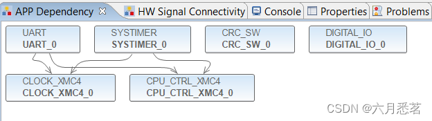
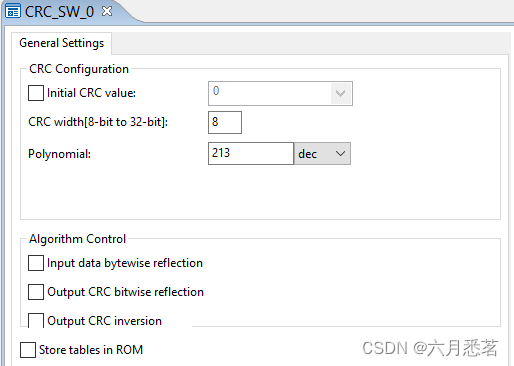
- CRC_SW APP is used to calculate a CRC checksum based on a pre-determined polynomial. No
algorithm control is selected for the CRC calculation. - UART APP is used to receive the incoming data frame. The incoming frame is a 9-bytes frame
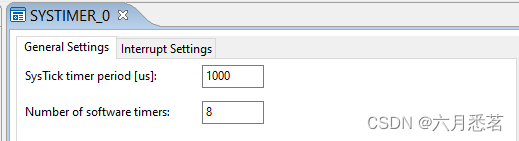
(8bytes data + 1byte CRC checksum). The 9th byte is the checksum byte. - SYSTIMER APP is used to generate a period SW timer of 0.5 seconds interval. It toggles the LED if checksum is matching, else LED is turned off.
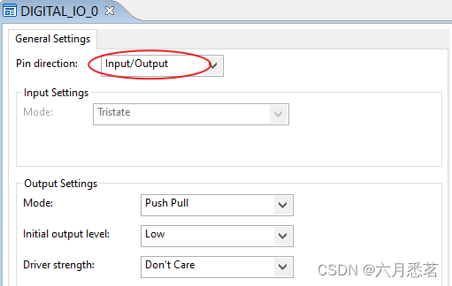
- DIGITAL_IO APP is used for LED toggling.
- Main program polls for a 9bytes data frame. The incoming frame (8 bytes data) is used to
calculate the CRC checksum. The result is used to compare against the checksum byte of the data frame. If result is matching, the LED toggles every 0.5 seconds, else LED is turned off.
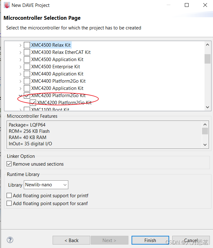
REQUIRMENTS:
Boards Required: XMC4200 Platform2Go Board
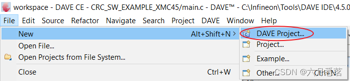
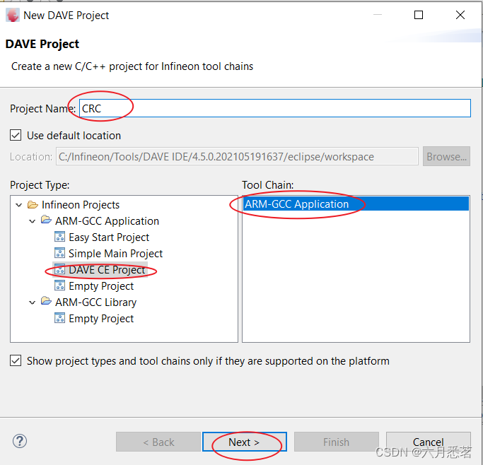
HOW TO CREATE THE PROJECT:
- Open the DAVE CE and use “Add IDE New Project Wizard” on the toolbar to add a new
DAVE Project.
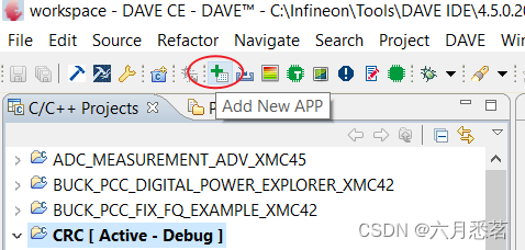
- Use the “Add New APP” in the toolbar to add APPs listed. Configure the App instances with
the following configurations.
- CRC_SW: Default settings taken.
- DIGITAL_IO_0:
- SYSTIMER_0: Default settings taken.
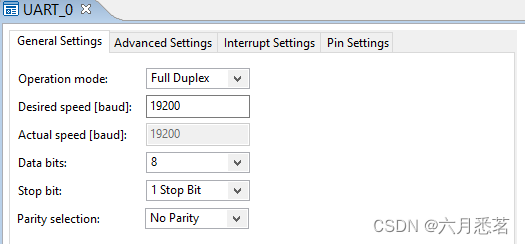
- UART_0: Default settings taken.
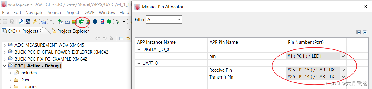
- Use the “Manual Pin Allocator” found in the toolbar, configure the output pin for the LED and
UART pins.
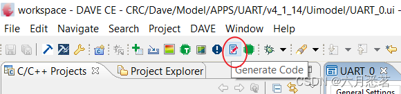
- Generate the code for configurations made and change main.c accordingly.
#include <DAVE.h>			//Declarations from DAVE Code Generation (includes SFR declarations)

uint8_t ReadData[9];
uint32_t CRCResult = 0;
uint32_t CRCResultmatch=0;

/**
 * @brief Periodic_Heartbeat()
 * SW timer triggered every 500ms. If CRC result matches, toggles LED. Else, LED is not turned on.
 */
void Periodic_Heartbeat(void)
{
	/*Toggles LED if CRC result matches with sent data frame*/
	if(CRCResultmatch)
	{
		DIGITAL_IO_ToggleOutput(&DIGITAL_IO_0);
	}
	else
	{
		DIGITAL_IO_SetOutputHigh(&DIGITAL_IO_0);
	}
}


/**
 * @brief main() - Application entry point
 * SW CRC is applied to an incoming frame to check the integrity of the received data. The incoming frame is a
 * 9-bytes frame (8bytes data + 1byte CRC checksum).
 */
int main(void)
{
  DAVE_STATUS_t status;
  uint32_t TimerId;

  status = DAVE_Init();		/* Initialization of DAVE Apps  */

  if(status == DAVE_STATUS_FAILURE)
  {
    /* Placeholder for error handler code. The while loop below can be replaced with an user error handler */
    XMC_DEBUG(("DAVE Apps initialization failed with status %d\n", status));
    while(1U)
    {
    }
  }

  /* Create Software Timer for LED evaluation and toggling*/
  TimerId = SYSTIMER_CreateTimer(500000U,SYSTIMER_MODE_PERIODIC,(void*)Periodic_Heartbeat,NULL);

  /* Start Software Timer */
  SYSTIMER_StartTimer(TimerId);


  /* Placeholder for user application code. The while loop below can be replaced with user application code. */
  while(1U)
  {
      /* Poll for data frame with 9 bytes of data. On data frame received, echo back the data to COM port
       * Data frame format: 8 bytes of data + 1 byte of CRC checksum
       */
	    UART_Receive(&UART_0, ReadData, 9);

	    while(UART_0.runtime->rx_busy)
        {
        }

        UART_Transmit(&UART_0, ReadData, 9);


	  /* Calculate the CRC based on the frame received. */
	  CRC_SW_CalculateCRC(&CRC_SW_0, ReadData, 8);

	  /* Read the CRC result */
      CRCResult = CRC_SW_GetCRCResult(&CRC_SW_0);

      /* Check if CRC result matches with dataframe result. If matches, CRCResultmatch=1 */
      if(CRCResult==ReadData[8])
      {
    	  CRCResultmatch=1;
      }
      else
      {
    	  CRCResultmatch=0;
      }
  }
}
- Build and download to the microcontroller.
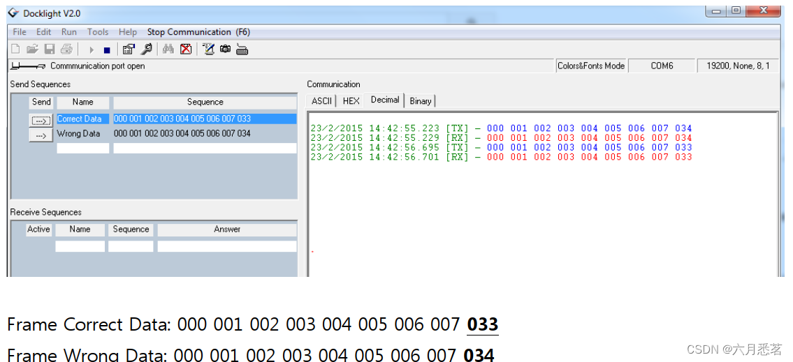
- Using a terminal program (e.g. Docklight, MTTY) to send the data to the microcontroller.
HOW TO TEST:
Download and run the demo in the uC.
OBSERVATIONS:
- When a “Frame Correct Data” is sent, LED toggles at 0.5 seconds interval .
- When a “Frame Wrong Data” is sent, LED turns off.


 660
660

 被折叠的 条评论
为什么被折叠?
被折叠的 条评论
为什么被折叠?
 到【灌水乐园】发言


