


 该文详细介绍了如何使用STM32进行PULS1和PULS2双路频率采集的配置,包括软件准备、CubeMx的设置、代码修改和中断处理。通过设置定时器TIM2和TIM3,实现了对两个通道的频率测量,并提供了测试代码和工程链接。
前言
我们学完了DHT11的应用之后,就开始学习双路IC采集频率
一、软件准备
1、MDK4或者MDK5(可到官网或者其他途径获取,本人使用的是MDK5)
2、Cubemx(可到官网自行下载)
3、安装G4的包(1.2.0,1.3.0以及1.4.0均可)
4、串口调试助手(COM)
二、PULS1,PULS2
1.扩展板上模块的原理图以及我们需要配置的元素
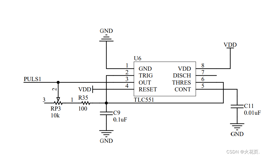
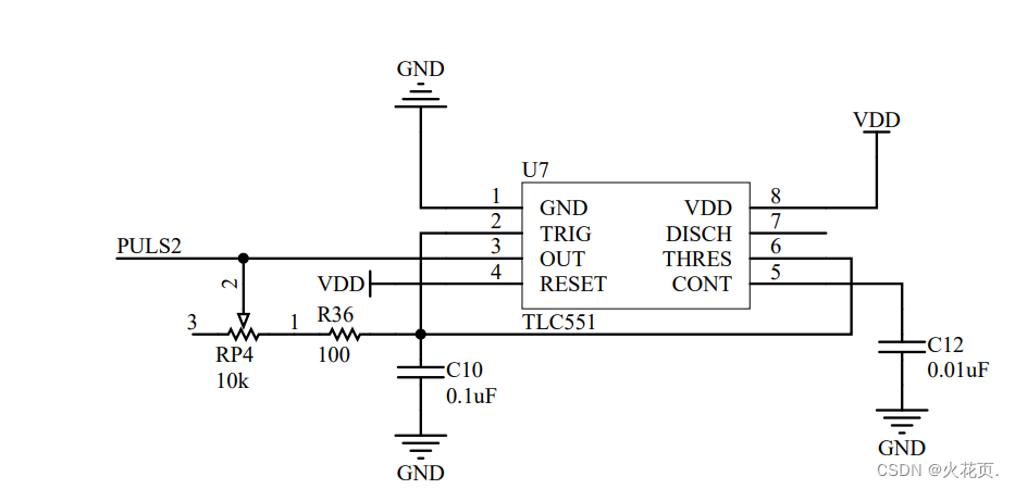
PULS1和PULS2部分原理图:
模块在扩展板的布局:
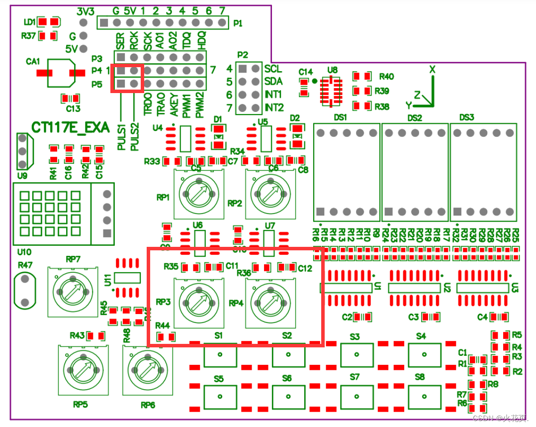 分析:如果要采集PULS1和PULS2则需要将PA1和PA2跳线到PULS1和PULS2。
2.CubeMx的配置步骤
RCC配置:略
设置调试接口:设置为Serial Wire
配置定时器TIM2:
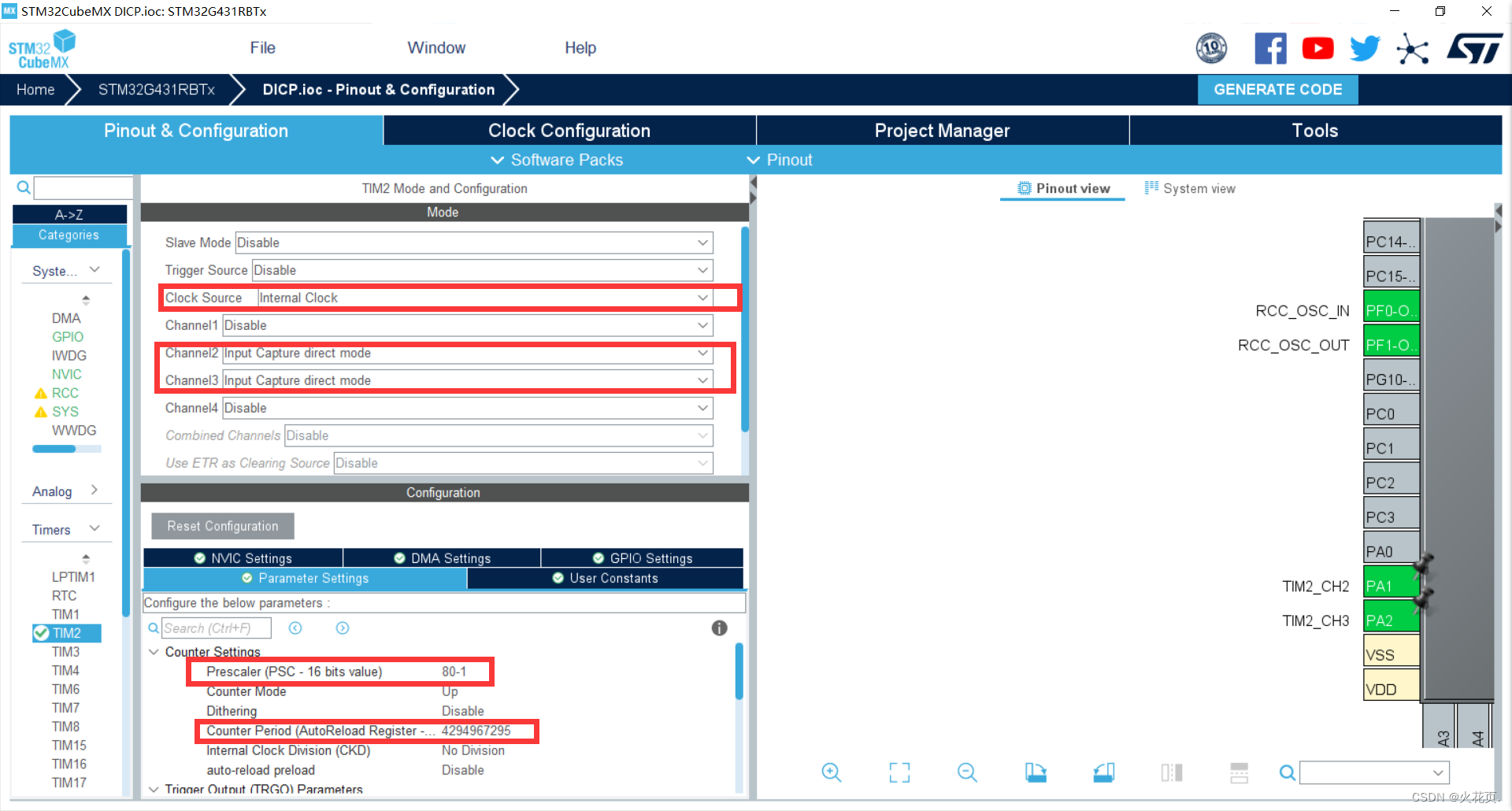
生成工程:点击GENERATE CODE生成工程。
3.代码添加及修改
打开赛点资源包->新版竞赛平台->新版竞赛平台->库文件->解压stm32cube_fw_g4_v120.zip->打开stm32cube_fw_g4_v120->STM32Cube_FW_G4_V1.2.0->Projects->NUCLEO-G431RB->Examples->TIM->TIM_InputCapture->src->main.c
在工程文件夹中创建自己的interrupt.h和interrupt.c并加入工程
创建一个空的C文件,但不要加入工程, 命名为temp.c
打开刚刚从库文件找到的main.c
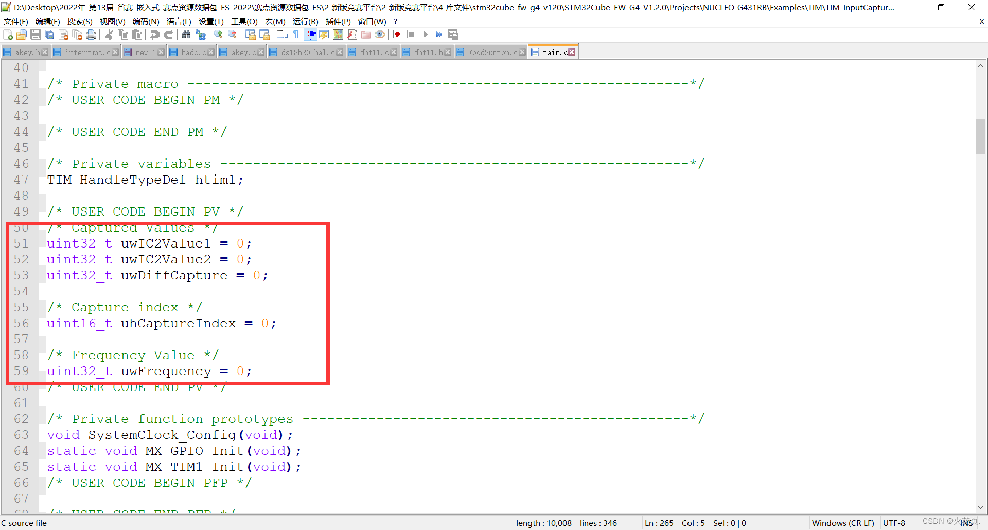
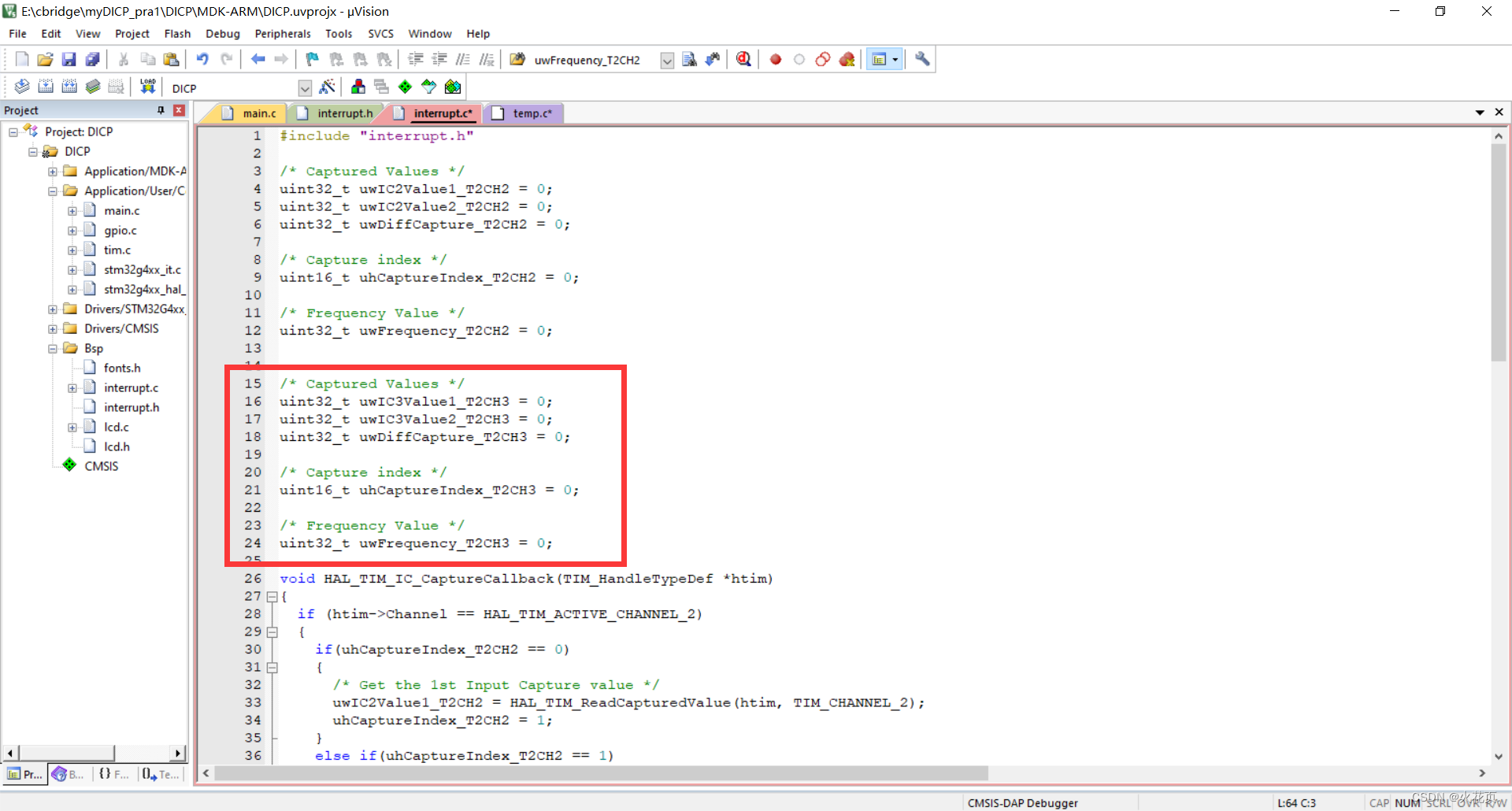
复制红框中的部分到temp.c
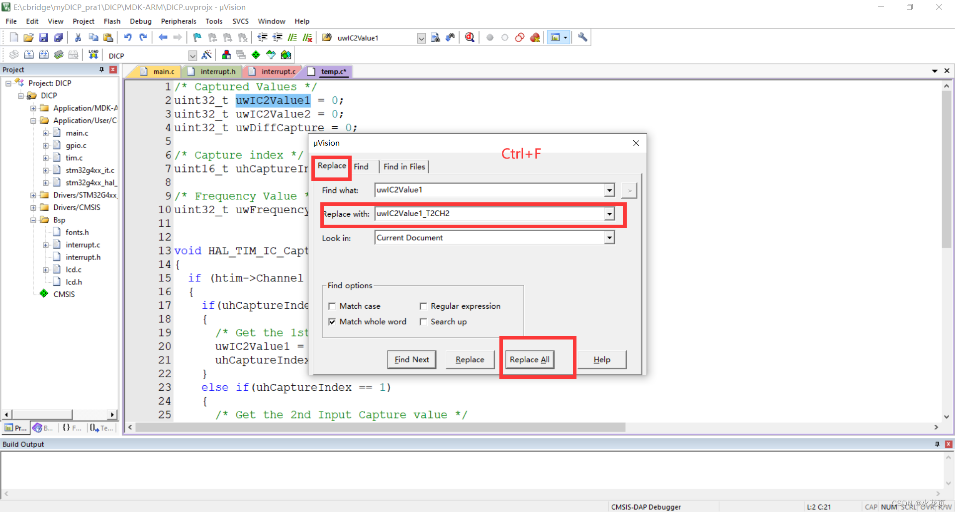
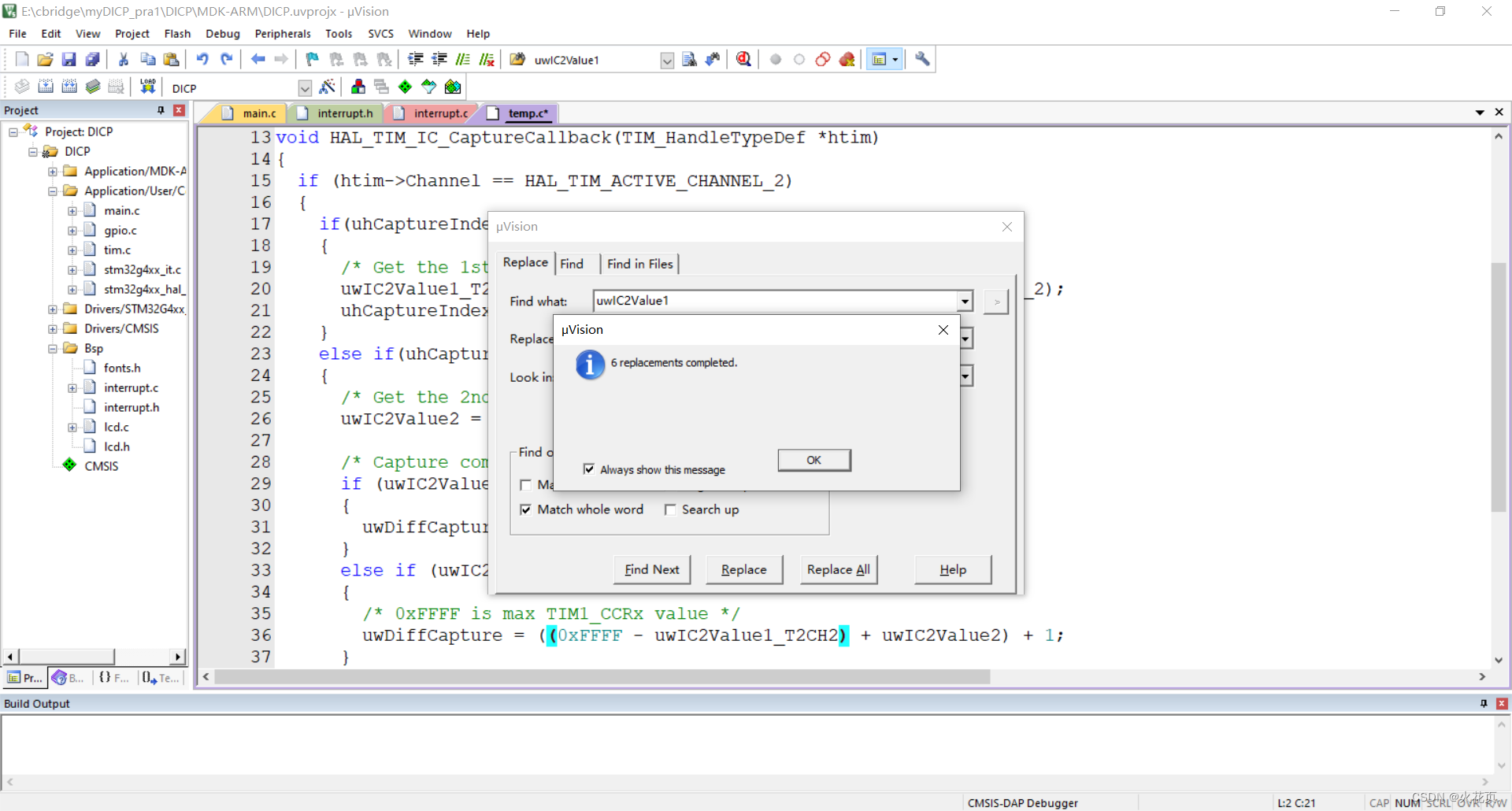
利用keil自带的Ctrl+F功能替换变量名字:
uwIC2Value1->uwIC2Value1_T2CH2
之后继续将
uwIC2Value2->uwIC2Value2_T2CH2, uwDiffCapture->uwDiffCapture_T2CH2
uhCaptureIndex->uhCaptureIndex_T2CH2,uwFrequency->uwFrequency_T2CH2
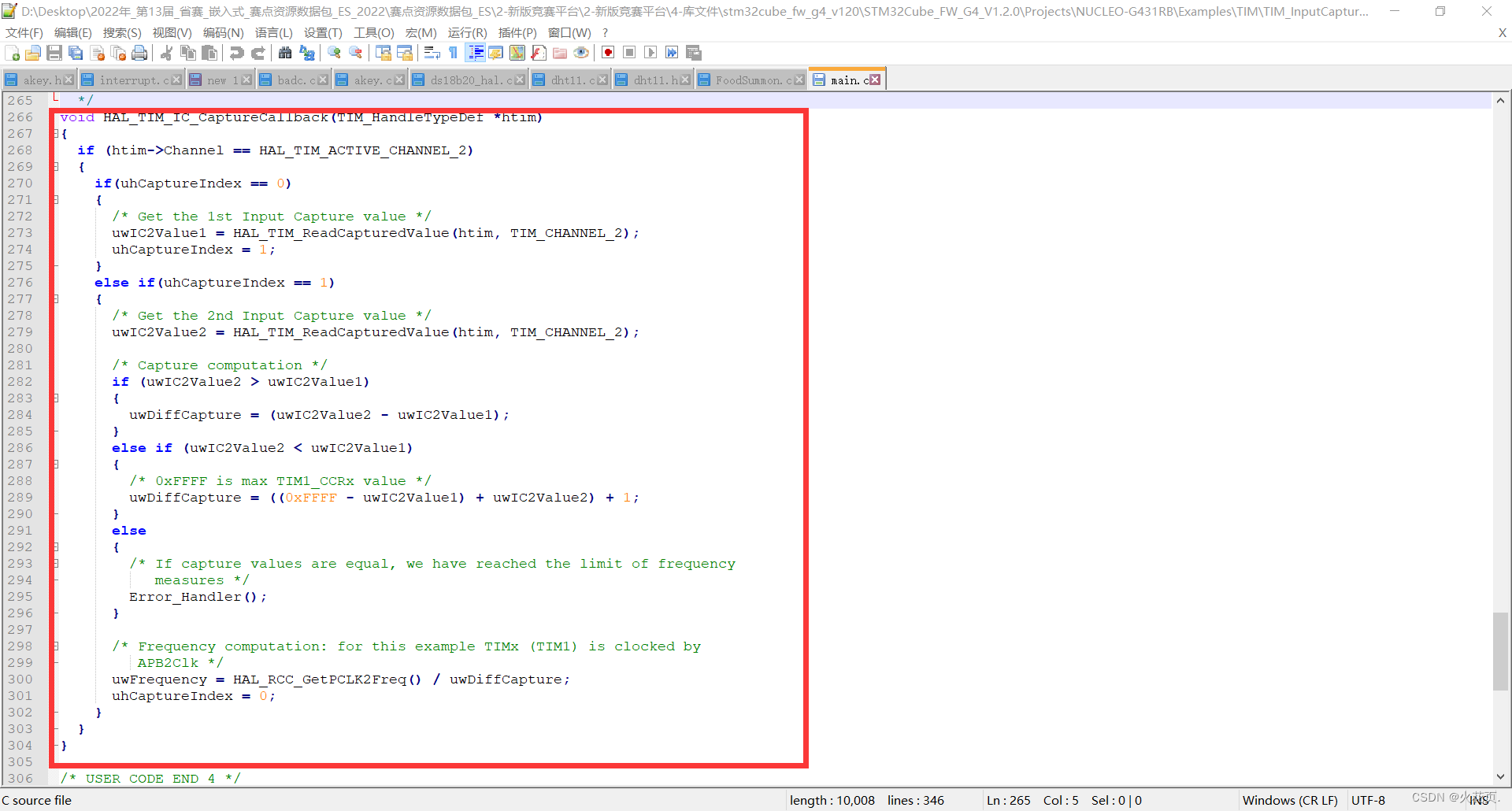
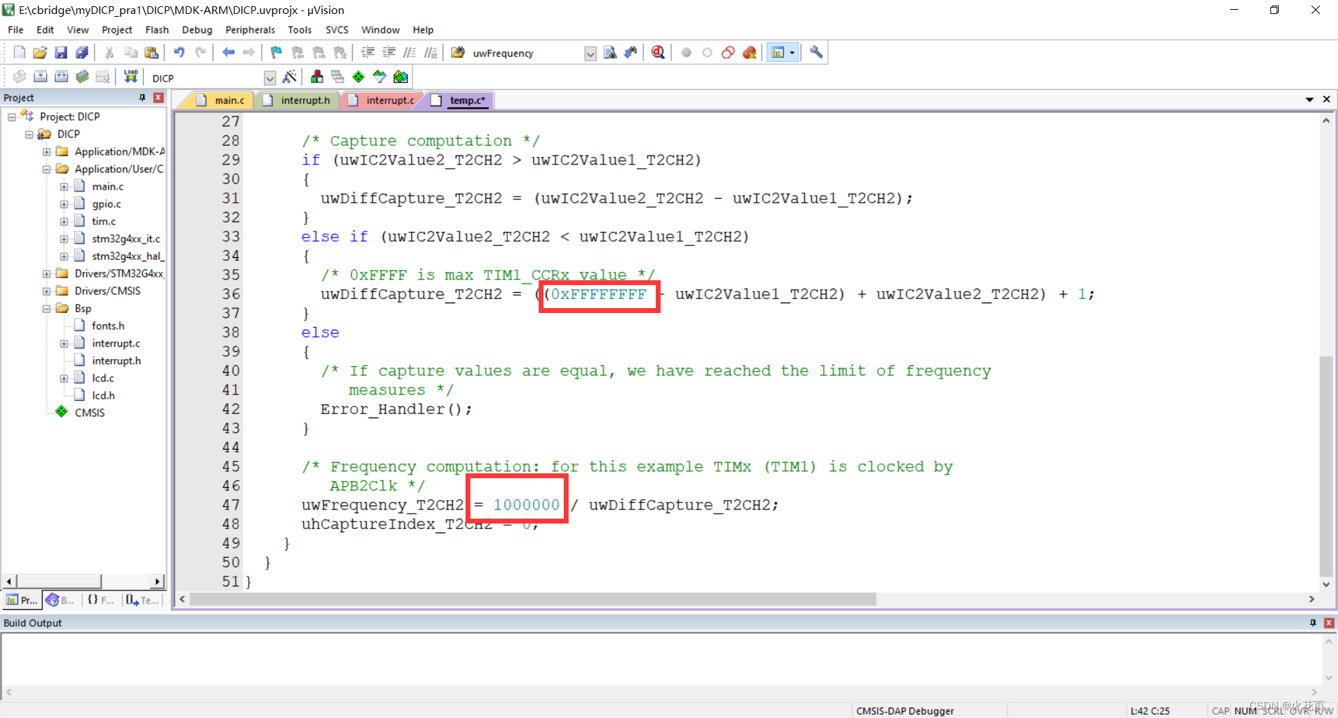
然后修改红框中的部分,将其改为图中的内容
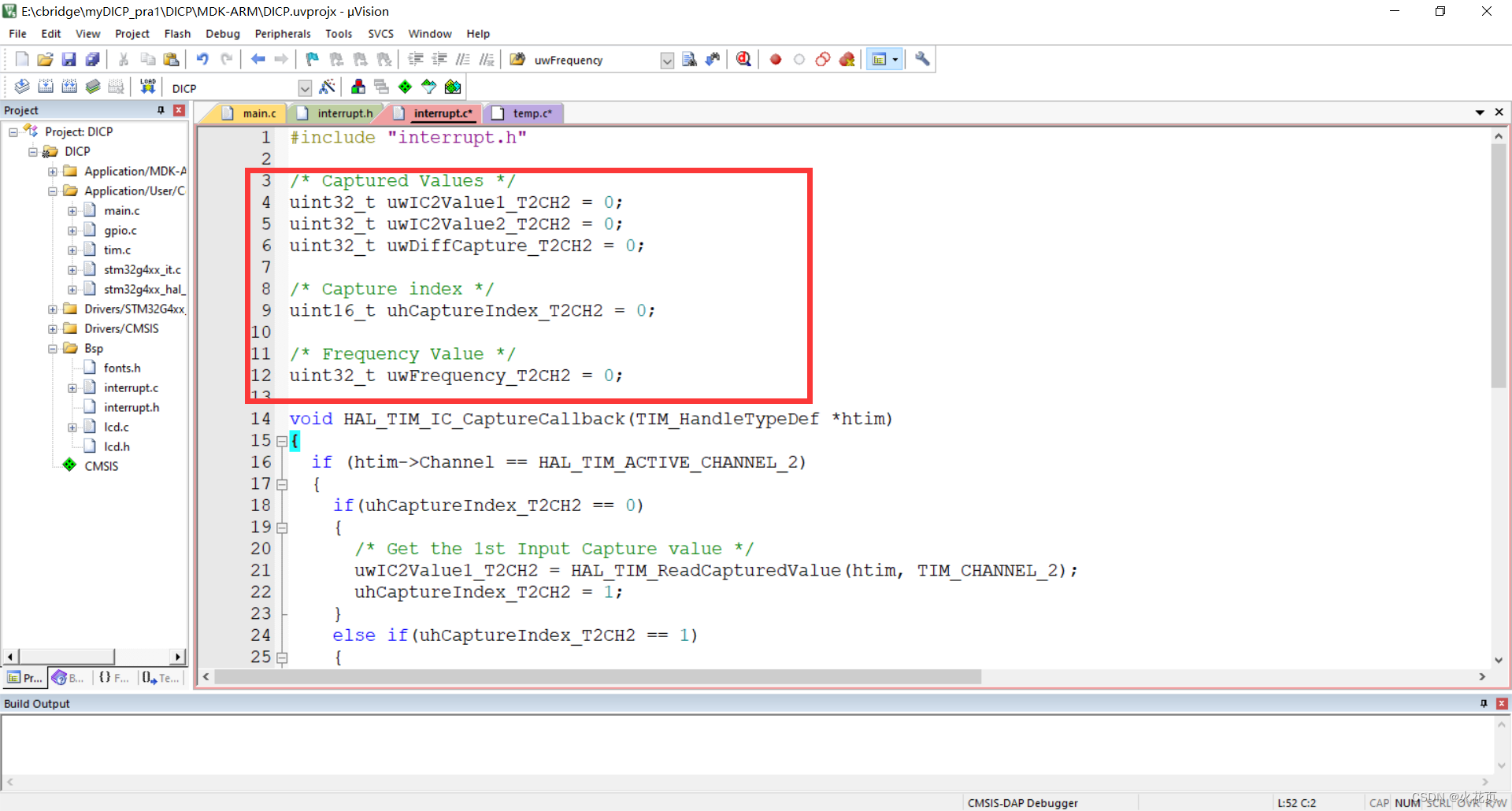
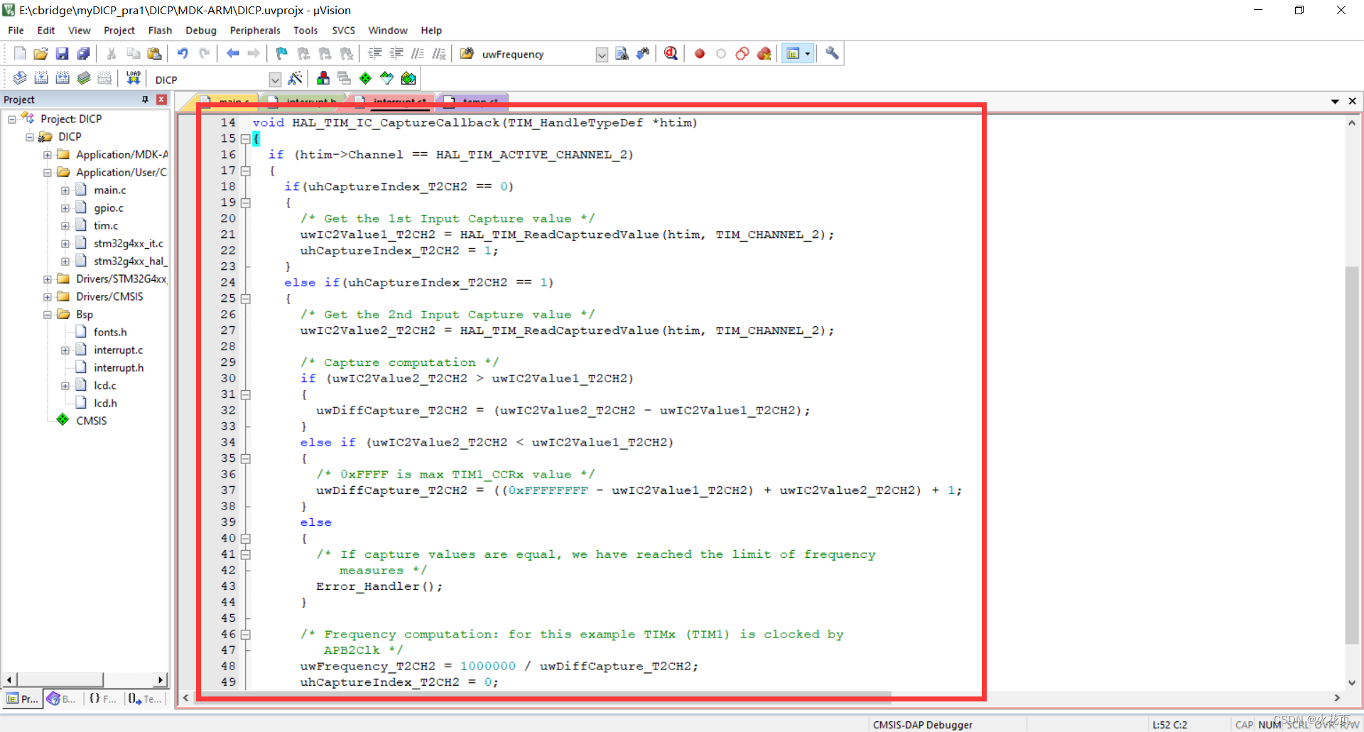
修改之后将变量定义和函数一起复制黏贴到interrupt.c中
再然后回到temp.c
修改变量:
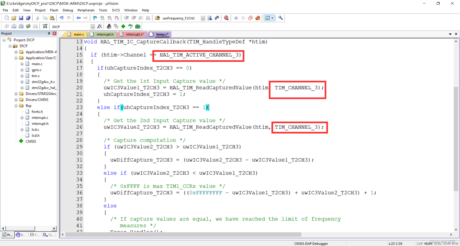
uwIC2Value1_T2CH2->uwIC3Value1_T2CH3
uwIC2Value2_T2CH2->uwIC3Value2_T2CH3
uwDiffCapture_T2CH2->uwDiffCapture_T2CH3
uhCaptureIndex_T2CH2->uhCaptureIndex_T2CH3
uwFrequency_T2CH2->uwFrequency_T2CH3
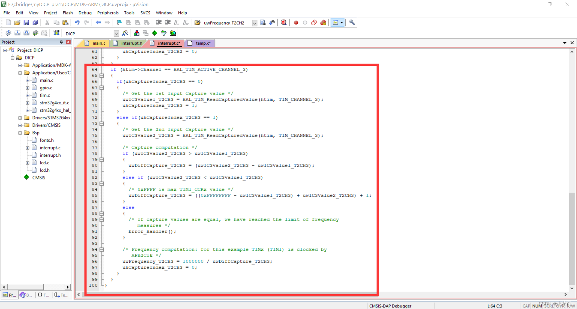
之后修改函数中的TIM_ACTIVE_CHANNEL_2为TIM_ACTIVE_CHANNEL_3
TIM_CHANNEL_2为TIM_CHANNEL_3
之后再将变量和函数部分粘贴到interrupt.c中
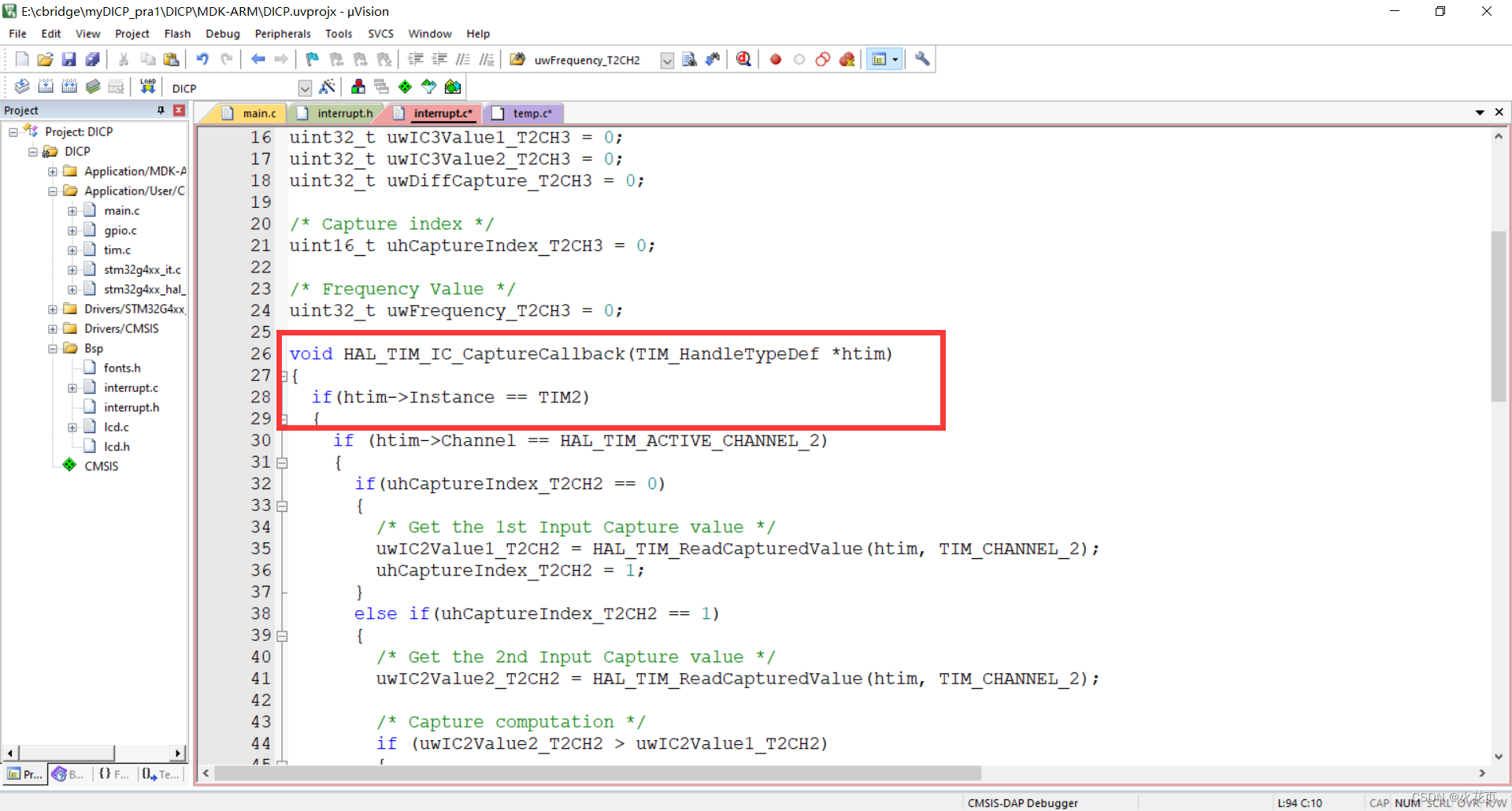
再在interrupt.c中的函数添加锁定定时器判断:
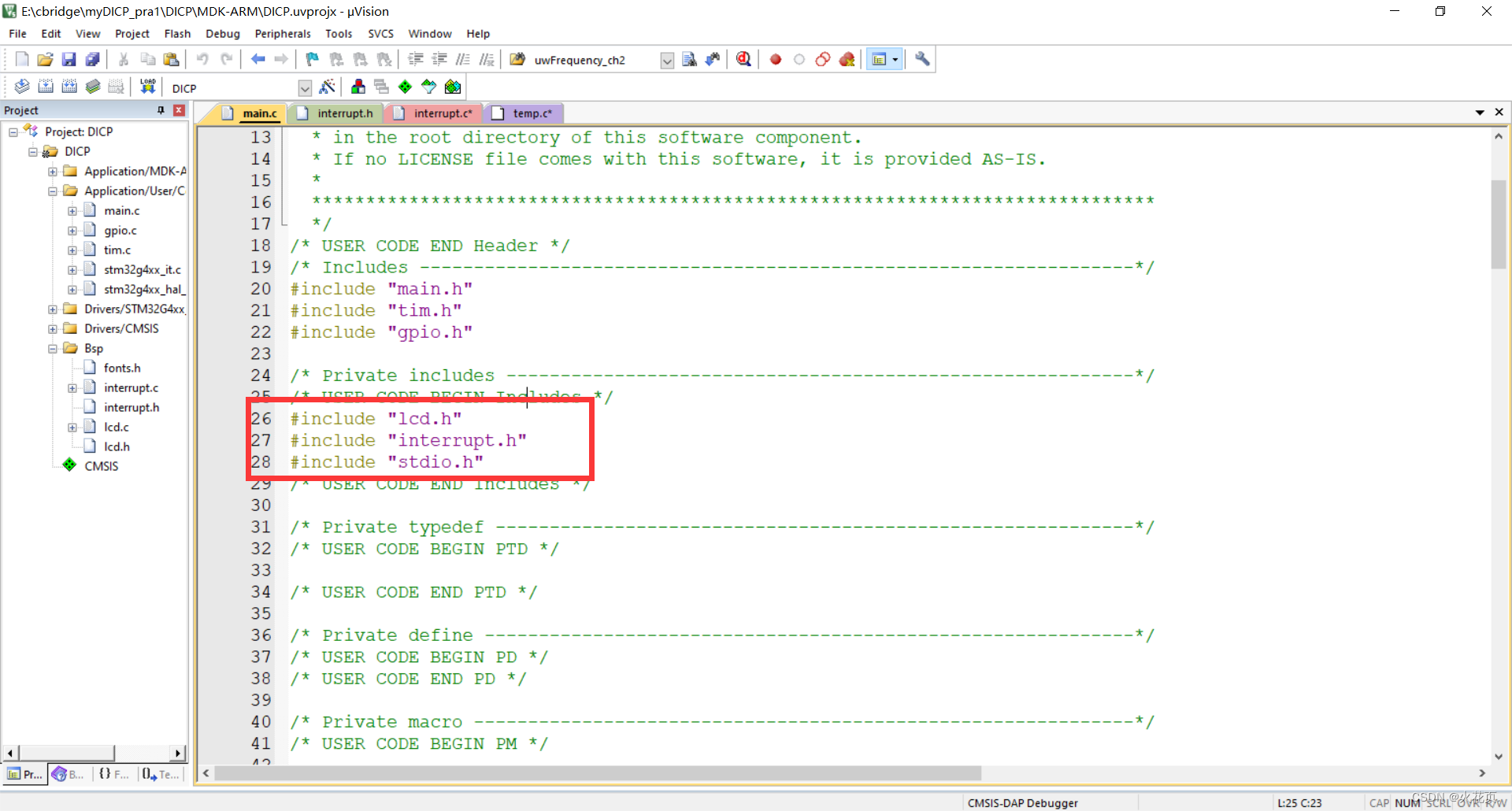
之后回到我们工程的main.c中:
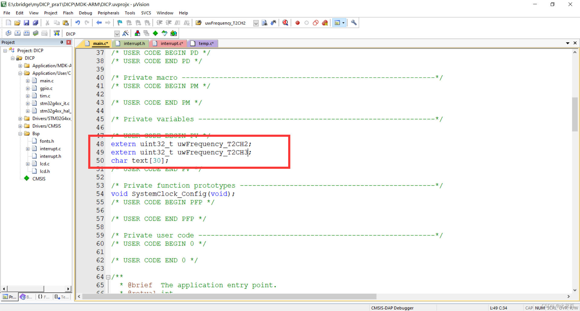
添加头文件:
添加变量:
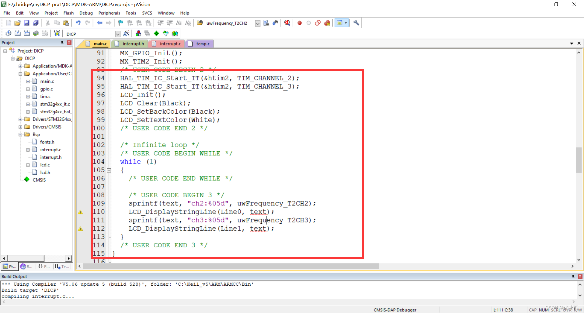
液晶初始化,以及开中断:
之后将temp.c删除即可
三、测试代码
代码修改完成之后,添加lcd.h, lcd.c, fonts.h到工程中以方便显示。
interrupt.h:
#ifndef __INTERRUPT_H__
#define __INTERRUPT_H__

#include "main.h"

#endif
interrupt.c:
#include "interrupt.h"

/* Captured Values */
uint32_t uwIC2Value1_T2CH2 = 0;
uint32_t uwIC2Value2_T2CH2 = 0;
uint32_t uwDiffCapture_T2CH2 = 0;

/* Capture index */
uint16_t uhCaptureIndex_T2CH2 = 0;

/* Frequency Value */
uint32_t uwFrequency_T2CH2 = 0;


/* Captured Values */
uint32_t uwIC3Value1_T2CH3 = 0;
uint32_t uwIC3Value2_T2CH3 = 0;
uint32_t uwDiffCapture_T2CH3 = 0;

/* Capture index */
uint16_t uhCaptureIndex_T2CH3 = 0;

/* Frequency Value */
uint32_t uwFrequency_T2CH3 = 0;

void HAL_TIM_IC_CaptureCallback(TIM_HandleTypeDef *htim)
{
	if(htim->Instance == TIM2)
	{
		if (htim->Channel == HAL_TIM_ACTIVE_CHANNEL_2)
		{
			if(uhCaptureIndex_T2CH2 == 0)
			{
				/* Get the 1st Input Capture value */
				uwIC2Value1_T2CH2 = HAL_TIM_ReadCapturedValue(htim, TIM_CHANNEL_2);
				uhCaptureIndex_T2CH2 = 1;
			}
			else if(uhCaptureIndex_T2CH2 == 1)
			{
				/* Get the 2nd Input Capture value */
				uwIC2Value2_T2CH2 = HAL_TIM_ReadCapturedValue(htim, TIM_CHANNEL_2);

				/* Capture computation */
				if (uwIC2Value2_T2CH2 > uwIC2Value1_T2CH2)
				{
					uwDiffCapture_T2CH2 = (uwIC2Value2_T2CH2 - uwIC2Value1_T2CH2);
				}
				else if (uwIC2Value2_T2CH2 < uwIC2Value1_T2CH2)
				{
					/* 0xFFFF is max TIM1_CCRx value */
					uwDiffCapture_T2CH2 = ((0xFFFFFFFF - uwIC2Value1_T2CH2) + uwIC2Value2_T2CH2) + 1;
				}
				else
				{
					/* If capture values are equal, we have reached the limit of frequency
						 measures */
					Error_Handler();
				}

				/* Frequency computation: for this example TIMx (TIM1) is clocked by
					 APB2Clk */
				uwFrequency_T2CH2 = 1000000 / uwDiffCapture_T2CH2;
				uhCaptureIndex_T2CH2 = 0;
			}
		}
		if (htim->Channel == HAL_TIM_ACTIVE_CHANNEL_3)
		{
			if(uhCaptureIndex_T2CH3 == 0)
			{
				/* Get the 1st Input Capture value */
				uwIC3Value1_T2CH3 = HAL_TIM_ReadCapturedValue(htim, TIM_CHANNEL_3);
				uhCaptureIndex_T2CH3 = 1;
			}
			else if(uhCaptureIndex_T2CH3 == 1)
			{
				/* Get the 2nd Input Capture value */
				uwIC3Value2_T2CH3 = HAL_TIM_ReadCapturedValue(htim, TIM_CHANNEL_3);

				/* Capture computation */
				if (uwIC3Value2_T2CH3 > uwIC3Value1_T2CH3)
				{
					uwDiffCapture_T2CH3 = (uwIC3Value2_T2CH3 - uwIC3Value1_T2CH3);
				}
				else if (uwIC3Value2_T2CH3 < uwIC3Value1_T2CH3)
				{
					/* 0xFFFF is max TIM1_CCRx value */
					uwDiffCapture_T2CH3 = ((0xFFFFFFFF - uwIC3Value1_T2CH3) + uwIC3Value2_T2CH3) + 1;
				}
				else
				{
					/* If capture values are equal, we have reached the limit of frequency
						 measures */
					Error_Handler();
				}

				/* Frequency computation: for this example TIMx (TIM1) is clocked by
					 APB2Clk */
				uwFrequency_T2CH3 = 1000000 / uwDiffCapture_T2CH3;
				uhCaptureIndex_T2CH3 = 0;
			}
		}
	}
}
main.h:没有做修改所以不放出
main.c:
/* USER CODE BEGIN Header */
/**
  ******************************************************************************
  * @file           : main.c
  * @brief          : Main program body
  ******************************************************************************
  * @attention
  *
  * Copyright (c) 2023 STMicroelectronics.
  * All rights reserved.
  *
  * This software is licensed under terms that can be found in the LICENSE file
  * in the root directory of this software component.
  * If no LICENSE file comes with this software, it is provided AS-IS.
  *
  ******************************************************************************
  */
/* USER CODE END Header */
/* Includes ------------------------------------------------------------------*/
#include "main.h"
#include "tim.h"
#include "gpio.h"

/* Private includes ----------------------------------------------------------*/
/* USER CODE BEGIN Includes */
#include "lcd.h"
#include "interrupt.h"
#include "stdio.h"
/* USER CODE END Includes */

/* Private typedef -----------------------------------------------------------*/
/* USER CODE BEGIN PTD */

/* USER CODE END PTD */

/* Private define ------------------------------------------------------------*/
/* USER CODE BEGIN PD */
/* USER CODE END PD */

/* Private macro -------------------------------------------------------------*/
/* USER CODE BEGIN PM */

/* USER CODE END PM */

/* Private variables ---------------------------------------------------------*/

/* USER CODE BEGIN PV */
extern uint32_t uwFrequency_T2CH2;
extern uint32_t uwFrequency_T2CH3;
char text[30];
/* USER CODE END PV */

/* Private function prototypes -----------------------------------------------*/
void SystemClock_Config(void);
/* USER CODE BEGIN PFP */

/* USER CODE END PFP */

/* Private user code ---------------------------------------------------------*/
/* USER CODE BEGIN 0 */

/* USER CODE END 0 */

/**
  * @brief  The application entry point.
  * @retval int
  */
int main(void)
{
  /* USER CODE BEGIN 1 */

  /* USER CODE END 1 */

  /* MCU Configuration--------------------------------------------------------*/

  /* Reset of all peripherals, Initializes the Flash interface and the Systick. */
  HAL_Init();

  /* USER CODE BEGIN Init */

  /* USER CODE END Init */

  /* Configure the system clock */
  SystemClock_Config();

  /* USER CODE BEGIN SysInit */

  /* USER CODE END SysInit */

  /* Initialize all configured peripherals */
  MX_GPIO_Init();
  MX_TIM2_Init();
  /* USER CODE BEGIN 2 */
	HAL_TIM_IC_Start_IT(&htim2, TIM_CHANNEL_2);
	HAL_TIM_IC_Start_IT(&htim2, TIM_CHANNEL_3);
	LCD_Init();
	LCD_Clear(Black);
	LCD_SetBackColor(Black);
	LCD_SetTextColor(White);
  /* USER CODE END 2 */

  /* Infinite loop */
  /* USER CODE BEGIN WHILE */
  while (1)
  {
    /* USER CODE END WHILE */

    /* USER CODE BEGIN 3 */
		sprintf(text, "ch2:%05d", uwFrequency_T2CH2);
		LCD_DisplayStringLine(Line0, text);
		sprintf(text, "ch3:%05d", uwFrequency_T2CH3);
		LCD_DisplayStringLine(Line1, text);
  }
  /* USER CODE END 3 */
}

/**
  * @brief System Clock Configuration
  * @retval None
  */
void SystemClock_Config(void)
{
  RCC_OscInitTypeDef RCC_OscInitStruct = {0};
  RCC_ClkInitTypeDef RCC_ClkInitStruct = {0};

  /** Configure the main internal regulator output voltage
  */
  HAL_PWREx_ControlVoltageScaling(PWR_REGULATOR_VOLTAGE_SCALE1);

  /** Initializes the RCC Oscillators according to the specified parameters
  * in the RCC_OscInitTypeDef structure.
  */
  RCC_OscInitStruct.OscillatorType = RCC_OSCILLATORTYPE_HSE;
  RCC_OscInitStruct.HSEState = RCC_HSE_ON;
  RCC_OscInitStruct.PLL.PLLState = RCC_PLL_ON;
  RCC_OscInitStruct.PLL.PLLSource = RCC_PLLSOURCE_HSE;
  RCC_OscInitStruct.PLL.PLLM = RCC_PLLM_DIV3;
  RCC_OscInitStruct.PLL.PLLN = 20;
  RCC_OscInitStruct.PLL.PLLP = RCC_PLLP_DIV2;
  RCC_OscInitStruct.PLL.PLLQ = RCC_PLLQ_DIV2;
  RCC_OscInitStruct.PLL.PLLR = RCC_PLLR_DIV2;
  if (HAL_RCC_OscConfig(&RCC_OscInitStruct) != HAL_OK)
  {
    Error_Handler();
  }

  /** Initializes the CPU, AHB and APB buses clocks
  */
  RCC_ClkInitStruct.ClockType = RCC_CLOCKTYPE_HCLK|RCC_CLOCKTYPE_SYSCLK
                              |RCC_CLOCKTYPE_PCLK1|RCC_CLOCKTYPE_PCLK2;
  RCC_ClkInitStruct.SYSCLKSource = RCC_SYSCLKSOURCE_PLLCLK;
  RCC_ClkInitStruct.AHBCLKDivider = RCC_SYSCLK_DIV1;
  RCC_ClkInitStruct.APB1CLKDivider = RCC_HCLK_DIV1;
  RCC_ClkInitStruct.APB2CLKDivider = RCC_HCLK_DIV1;

  if (HAL_RCC_ClockConfig(&RCC_ClkInitStruct, FLASH_LATENCY_2) != HAL_OK)
  {
    Error_Handler();
  }
}

/* USER CODE BEGIN 4 */

/* USER CODE END 4 */

/**
  * @brief  This function is executed in case of error occurrence.
  * @retval None
  */
void Error_Handler(void)
{
  /* USER CODE BEGIN Error_Handler_Debug */
  /* User can add his own implementation to report the HAL error return state */
  __disable_irq();
  while (1)
  {
  }
  /* USER CODE END Error_Handler_Debug */
}

#ifdef  USE_FULL_ASSERT
/**
  * @brief  Reports the name of the source file and the source line number
  *         where the assert_param error has occurred.
  * @param  file: pointer to the source file name
  * @param  line: assert_param error line source number
  * @retval None
  */
void assert_failed(uint8_t *file, uint32_t line)
{
  /* USER CODE BEGIN 6 */
  /* User can add his own implementation to report the file name and line number,
     ex: printf("Wrong parameters value: file %s on line %d\r\n", file, line) */
  /* USER CODE END 6 */
}
#endif /* USE_FULL_ASSERT */
四、演示效果

五、工程链接
六、总结
以上就是双路IC采集频率的配置过程,测试代码以及测试效果
以往的扩展板模块:
【STM32G431RBTx】备战蓝桥杯嵌入式→扩展模块→SEG
【STM32G431RBTx】备战蓝桥杯嵌入式→扩展模块→双路ADC/AO1, AO2
【STM32G431RBTx】备战蓝桥杯嵌入式→扩展模块→光敏电阻/TRAO, TRAO
【STM32G431RBTx】备战蓝桥杯嵌入式→扩展模块→AKEY
【STM32G431RBTx】备战蓝桥杯嵌入式→扩展模块→DS18B20
【STM32G431RBTx】备战蓝桥杯嵌入式→扩展模块→DHT11


 被折叠的 条评论
为什么被折叠?
被折叠的 条评论
为什么被折叠?
 到【灌水乐园】发言


