


 本文介绍了毫米波雷达用于3D点云生成的创新方法——MilliPoint,通过结合SAR技术克服了分辨率低和镜面反射问题。研究提出自我交叉范围跟踪和多焦点算法,实现对车辆雷达的SAR功能,生成密集高分辨率的点云。实验表明,MilliPoint在不同场景下能生成最密集且准确对齐的点云。
毫米波点云生成论文 | 3D Point Cloud Generation with Millimeter-Wave Radar
Kun Qian, Zhaoyuan He, Xinyu Zhang
UCSD
Proceedings of the ACM on Interactive, Mobile, Wearable and Ubiquitous Technologies (ACM IMWUT)
原始论文地址: http://xyzhang.ucsd.edu/papers/KQian_UbiComp21_RadarPointCloud.pdf
Video地址:ACM SIGCHI官方频道
本文为毫米波点云生成论文
3D Point Cloud Generation with Millimeter-Wave Radar的阅读笔记, 原载于R.X. NLOS的博客
大量参考了作者的 Pre-recorded presentations for UbiComp/ISWC 2021, September 21–26
笔记难免存在问题,欢迎联系 981591477@qq.com 指正。
内容在优快云、知乎和微信公众号同步更新

文章目录
1 Introduction
- Sensors for Automomous Driving
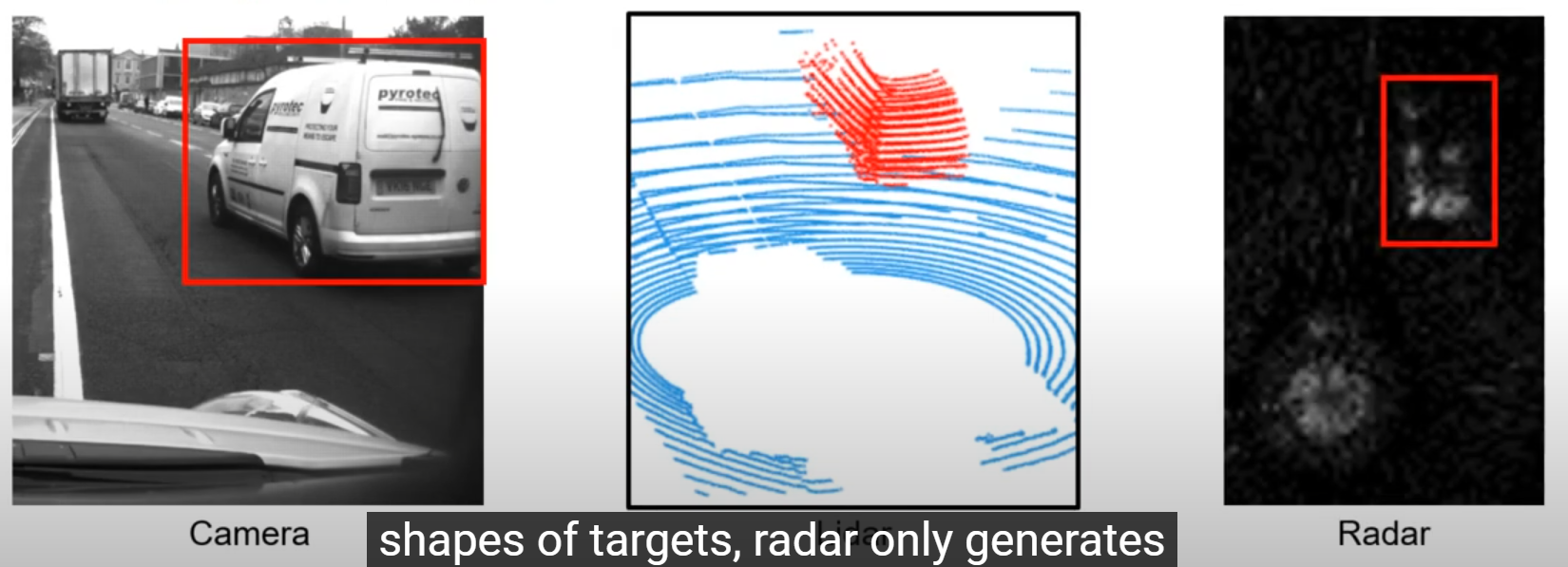
- Lidar, Camera and Radar
- Radar is more robust against bad weathers
- Limitations of MmWave Radar (2 main drawbacks)
-
Extremely low resolution
❌ due to its small form factor
❌ only generates intensity maps with strong reflection peaks
-
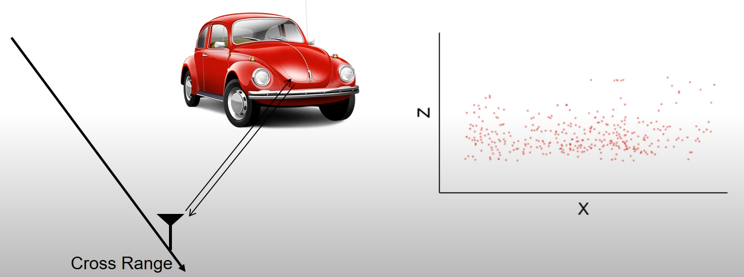
Blindness due to specular reflection
❌ specularly reflected by most objects
-
- An Existing Solution: Non-coherent Imaging
-
Fusing measurements along the Radar’s moving trajectory
✅ To some extent, alleviate the specular reflection problem (by illuminating from diverse locations)
❌ The imaging resolution is still limited by the physical size of the antenna array
❌ Cannot be fundamentally improved through spatial sampling
-
- MilliPoint: Coherent Imaging
-
Raw radar measurements are directly combined with SAR
✅ low-end vehicle radars
✅ coherently combines measurements of the radar
✅ generate dense and high-resolution 3D point clouds
-
2 困难和解决方法
- Enabling SAR with Vehicle Radar
- Challenge 1: SAR requires accurate tracking of the radar
- 左图:uniform motion (位置已知)
- 右图: Variable motion (位置未知)、
- 结论: Without the knowledage of the radar’s location, the image of the object can be highly distorted
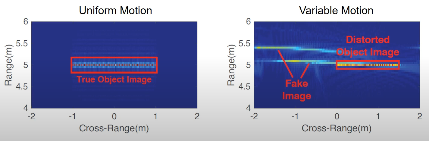
- Solution: a self cross-range tracking method
-
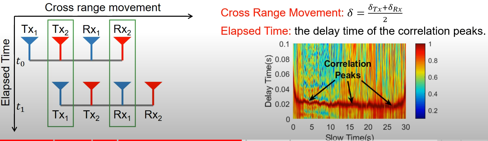
Radar Speed = Cross Range Movement / Elapsed Time
-
Observation: Different Tx-Rx pairs experience similar channel responses while moving along the cross-range
▪ The radar has equally spaced 4 antennas
▪ As the radar moves, the 1st antenna pair at time t 1 t_1 t1 coincides with the 2nd antenna pair at time t 0 t_0 t0
🚩 ⇒ \Rightarrow ⇒ pair 1和 pair 2接收的信号很接近,只有一个 t 0 − t 1 t_0 - t_1 t0−t1的时延 ⇒ \Rightarrow ⇒ 由测量信号可获得 t 0 − t 1 t_0 - t_1 t0−t1
▪ 同时,the radar moves by one antenna spacing ⇒ \Rightarrow ⇒ 可获得距离 (cross-range movement)
▪ so the speed of the radar can be calculated
-
-
Overcoming Specular Reflection in SAR
-
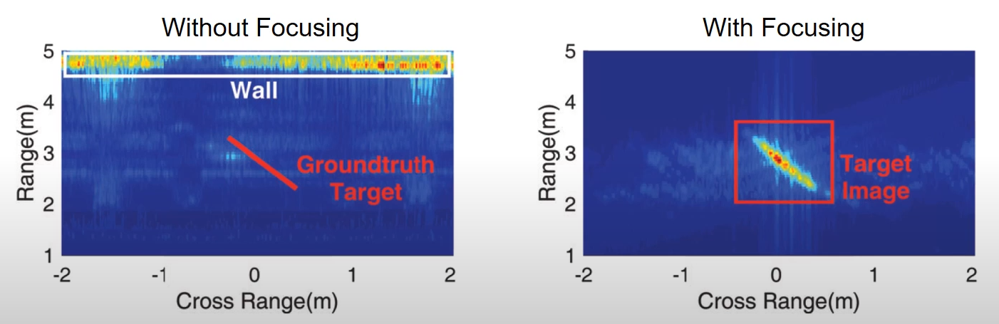
Challenge 2: SAR requires focusing on the center of the target
- 下图:the scenario where a metal surface is 3m away and 沿cross-range方向 135 ∘ ^\circ ∘ incident angle
- 左图:SAR focuses on the broadside direction, then the target disappears
- 右图:only when the SAR focuses on the direction of 4 5 ∘ 45^\circ 45∘, the target is imaged
- Solution:
-
root cause of this phenomenon:
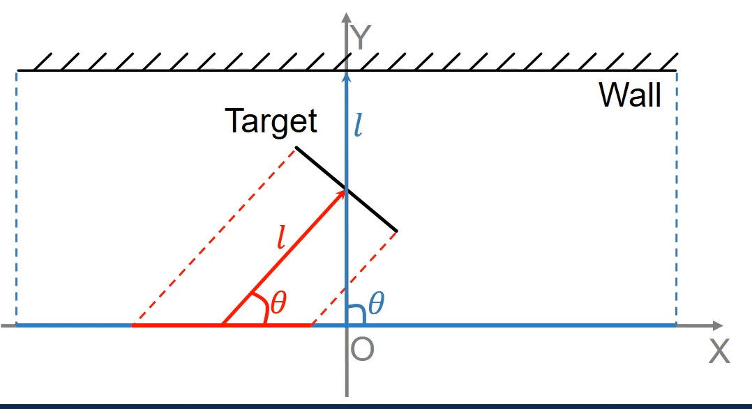
🚩 the mismatch of the physical aperture of the radar and the effective apertures of the targets
🚩 The physical aperture: the physical trajectory of the radar (图中blue segment)
🚩 The effective aperture of a target is the segment of the trajectory where the target’s reflection is received ⇒ \Rightarrow ⇒ Due to specular reflection, the effective aperture is the projection (图中short red segment)
-
The focusing center can be represented by the parameters l l l and θ \theta θ
✅ can be identified in the spatial frequency spectrum
✅ ⇒ \Rightarrow ⇒ 从而propose the multi-focusing algorithm to overcome the specular reflection problem and image all objects in the environment
✅ ⇒ \Rightarrow ⇒ image all objects in the environment
-
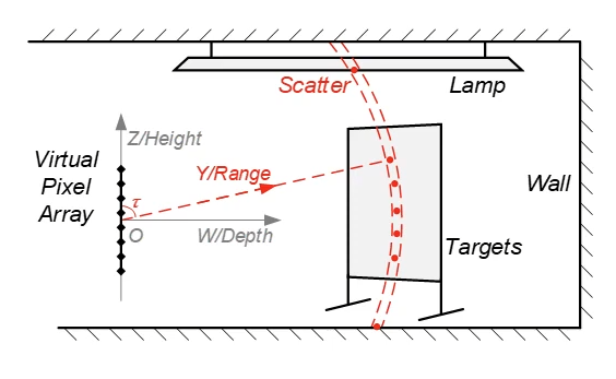
- 3D Point Cloud Generation from SAR
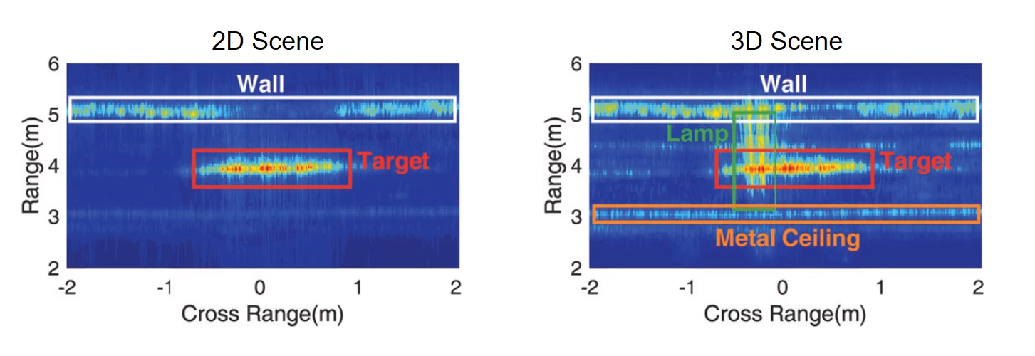
- Challenge 3: SAR only generates 2D intensity maps
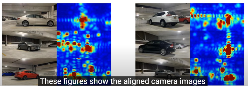
- 下图展示了an indoor scenario
- images of objects at different heights overlap with each other
- Solution:
-
Combining co-registered pixels of the SAR images generated by different antenna pairs to estimate the height of target scatter point
✅ exploit multiple antenna pairs along the vertical direction
✅ For each antenna pair, we generate one SAR image and find pixels with high intensity
✅ Complex pixel values still encode the elevation information ⇒ \Rightarrow ⇒ So we combine the co-registered pixels of all SAR images to form a virtual pixel array and estimate the elevation of the pixels (如下图)
-
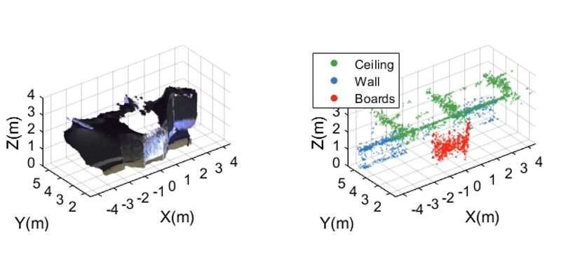
- 点云生成结果
3 实验与结果
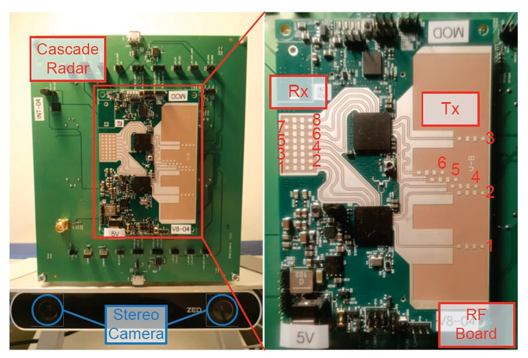
- Experiment
- using a TI cascade radar with 6 transmit antennas and 8 receive antennas
- Ground Truth: captured by a ZED stereo camera
- Results
- Compare MilliPoint with non-coherent imaging and the imaging with a static radar
- In different scenarios with different objects such as cars, pedestrians, bikes and trash bins, MilliPoint generates the densest point cloud s and the points 实现了accurately aligned
总结
-
理论方面 :Propose MilliPoint
-
The first step to enable 高分辨高密度 3D point cloud generation on low-end vehicle Radar based on SAR
-
关键挑战:
🚩 Self corss-range tracking
🚩 Automatic multi-focusing
🚩 3D pointcloud generation
-
-
实验方面 :implement and verify the design on an automative radar, and conduct case studies in realstic driving scenes
-
更多 :envision MilliPoint as a new type of sensor fusion modality


 被折叠的 条评论
为什么被折叠?
被折叠的 条评论
为什么被折叠?
 到【灌水乐园】发言


