


 本文介绍了SystemVerilog的interface概念,包括如何定义端口方向、如何连接interface与DUT,以及interface带来的好处。此外,讲解了clocking block在testbench中的作用,对比了Verilog与SystemVerilog中接口的差异,并展示了interface的参数化、数组使用及modport的应用,强调了interface在简化设计连接、提高可维护性方面的优势。
1. Interface 初识
接口是一种将信号封装到block中的方法。
语法
interface[name]([port_list]);
	[list_of_signals]
endinterface
接口还可以具有函数、任务、变量和参数,使其更像一个类模板。它还可以通过 modport 结构定义不同模块端口的方向信息策略,以及带有时钟块的 testbench 同步功能。它还可以有断言、覆盖率记录和其他协议检查元素。它还可以包含initial过程和always过程以及连续赋值(assign)语句。
模块不能在接口中实例化! 但是接口可以在模块中实例化。
interface apb_if (input pclk);
    logic[31:0]    paddr;
    logic[31:0]    pwdata;
    logic[31:0]    prdata;
    logic           penable;
    logic           pwrite;
    logic           psel;
endinterface
1.如何定义端口方向?
接口信号可用于各种验证组件以及 DUT,使用 modport 来定义信号方向。不同的 modport 定义可以传递给不同的组件,这样我们就可以为每个组件定义不同的输入输出方向。
interface myBus (input clk);
    logic[7:0]  data;
    logic      enable;
    // From TestBench perspective, 'data' is input and 'write' is output
    modport TB  (input data, clk,output enable);
    // From DUT perspective, 'data' is output and 'enable' is input
    modport DUT (output data,input enable, clk);
endinterface
2.如何连接interface与 DUT?
接口对象应该在实例化 DUT 的顶级 testbench 模块中创建,并传递给 DUT。确保为 DUT 分配正确的模型是非常重要的。
testbench模块中,接口对象在DUT前创建。
module dut (myBus busIf);
always @(posedge busIf.clk)
if(busIf.enable)
      busIf.data <= busIf.data+1;
else
      busIf.data <=0;
endmodule

// Filename : tb_top.sv
module tb_top;
    bit clk;
    // Create a clock
    always #10 clk =~clk;

    // Create an interface object
    myBus busIf (clk);

    // Instantiate the DUT; pass modport DUT of busIf
    dut dut0 (busIf.DUT);

    // Testbench code : let's wiggle enable
    initialbegin
        busIf.enable  <=0;
        #10 busIf.enable <=1;
        #40 busIf.enable <=0;
        #20 busIf.enable <=1;
        #100 $finish;
    end
endmodule
2.有什么好处?
接口可以包含任务、函数、参数、变量、函数覆盖和断言(tasks, functions, parameters, variables, functional coverage, and assertions.)。这使我们能够通过该块中的接口监视和记录事务。由于信息封装在一个接口中,不管它有多少个端口,连接到设计也变得更加容易。
3.如何参数化接口?
接口定义可以使用与模块定义相同的方式利用参数和参数重定义。下面的示例演示如何在接口定义中使用参数
interface myBus #(parameter D_WIDTH=31)(input clk);
	logic [D_WIDTH-1:0] data;
	logic enable;
endinterface

interface simple_bus #(AWIDTH = 8, DWIDTH = 8) (input logic clk); // Define the interface
	logic req, gnt;
	logic [AWIDTH-1:0] addr;
	logic [DWIDTH-1:0] data;
	logic [1:0] mode;
	logic start, rdy;
endinterface : simple_bus
clocking block
时钟块内指定的信号将相对于该时钟进行采样/驱动。在一个接口中可以有多个时钟块。
注意,这是用于 testbench 相关信号。控制 TB 何时驱动信号,何时从 DUT 采样信号。 解决了竞争条件的一部分,但不是全部。倾斜值(skew values)可以参数化。
interface my_int (inputbit clk);
	// Rest of interface code

	clocking cb_clk @(posedge clk);
		default input #3ns output #2ns;
		input enable;
		output data;
	endclocking
endinterface
在上面的例子中,指定默认情况下,input应该在 clk 的posedge 之前3ns 采样,output应该在clk 的posedge 之后2ns 被驱动。
// To wait for posedge of clock
@busIf.cb_clk;
// To use clocking block signals
busIf.cb_clk.enable =1;
在enable 赋值1之前,您不必等待 clk 的posedge。 这样,您可以确保在下一个posedge clk 后2ns 驱动enable。
clocking
它是与特定时钟同步的信号集合,有助于指定时钟与信号之间的定时要求。
这将使测试编写人员能够更多地关注事务,而不用担心信号什么时候会与时钟交互。一个 testbench 可以有许多时钟块,但是每个时钟只有一个时钟块。
语法
[default] clocking [identifier_name] @ [event_or_identifier]
	default input #[delay_or_edge] output #[delay_or_edge]
	[list of signals]
endclocking
delay_value表示一个信号被采样或驱动时离时钟事件有多少个时间单位的偏移。如果没有指定默认偏移,那么在指定的事件之后,所有的输入信号将采样 # 1步,输出信号驱动0ns。
2. interface intro
在 Verilog 和 SystemVerilog 中使用相同设计的接口。
Verilog 设计的interface
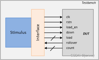
如何在测试平台中使用接口,并使用端口列表连接到标准的 Verilog 设计。下面显示的代码是 Verilog 编写的上下计数器的设计。这个模块接受一个参数来决定计数器的宽度。它还接受一个输入加载值 load,该加载值仅在 load_en 为1时加载到计数器中。
当输入向下为1时,计数器开始向下计数,否则向上计数。翻转输出指示计数器何时从最大值转换为0或从0转换为最大值。
module counter_ud  #(parameter WIDTH =4)(
    input 					clk,
    input 					rstn,
    inputwire[WIDTH-1:0]	load,
    input 					load_en,
    input 					down,
    output 					rollover,
    outputreg[WIDTH-1:0]	count
);
    always @(posedge clk ornegedge rstn)begin
        if(!rstn)
            count <=0;
        elseif(load_en)
            count <= load;
        else begin
            if(down)
                count <= count -1;
            else
                count <= count +1;
        end
    end
    assign rollover =&count;
endmodule
下面声明了一个名为 cnt_if 的接口,并使用可参数化的值作为计数器信号的宽度。 这个任务还有一个task init() 来赋值。
interface cnt_if #(parameter WIDTH = 4) (input bit clk);
  logic 			rstn;
  logic 			load_en;
  logic [WIDTH-1:0] load;
  logic [WIDTH-1:0] count;
  logic 			down;
  logic 			rollover;
endinterface

module tb;
  reg clk;

  // TB Clock Generator used to provide the design
  // with a clock -> here half_period = 10ns => 50 MHz
  always #10 clk = ~clk;

  cnt_if 	  cnt_if0 (clk);
  counter_ud  c0 ( 	.clk 		(cnt_if0.clk),
                  	.rstn 		(cnt_if0.rstn),
                  	.load 		(cnt_if0.load),
                  	.load_en 	(cnt_if0.load_en),
                  	.down 		(cnt_if0.down),
                  	.rollover 	(cnt_if0.rollover),
                  	.count 		(cnt_if0.count));

  initial begin
    bit load_en, down;
    bit [3:0] load;

    $monitor("[%0t] down=%0b load_en=%0b load=0x%0h count=0x%0h rollover=%0b",
    	$time, cnt_if0.down, cnt_if0.load_en, cnt_if0.load, cnt_if0.count, cnt_if0.rollover);

    // Initialize testbench variables
    clk <= 0;
    cnt_if0.rstn <= 0;
    cnt_if0.load_en <= 0;
    cnt_if0.load <= 0;
    cnt_if0.down <= 0;

    // Drive design out of reset after 5 clocks
    repeat (5) @(posedge clk);
    cnt_if0.rstn <= 1; // Drive stimulus -> repeat 5 times
    for (int i = 0; i < 5; i++) begin

      // Drive inputs after some random delay
      int delay = $urandom_range (1,30);
      #(delay);

      // Randomize input values to be driven
      std::randomize(load, load_en, down);

      // Assign tb values to interface signals
      cnt_if0.load <= load;
      cnt_if0.load_en <= load_en;
      cnt_if0.down <= down;
    end

    // Wait for 5 clocks and finish simulation
    repeat(5) @ (posedge clk);
    $finish;
  end
endmodule
ncsim> run
[0] down=0 load_en=0 load=0x0 count=0x0 rollover=0
[96] down=1 load_en=1 load=0x1 count=0x0 rollover=0
[102] down=0 load_en=0 load=0x9 count=0x0 rollover=0
[108] down=1 load_en=1 load=0x1 count=0x0 rollover=0
[110] down=1 load_en=1 load=0x1 count=0x1 rollover=0
[114] down=1 load_en=0 load=0xc count=0x1 rollover=0
[120] down=1 load_en=0 load=0x7 count=0x1 rollover=0
[130] down=1 load_en=0 load=0x7 count=0x0 rollover=0
[150] down=1 load_en=0 load=0x7 count=0xf rollover=1
[170] down=1 load_en=0 load=0x7 count=0xe rollover=0
[190] down=1 load_en=0 load=0x7 count=0xd rollover=0
Simulation complete via $finish(1) at time 210 NS + 0
SystemVerilog 设计的interface
现在让我们看看如何在测试工作台中使用接口并将其连接到 SystemVerilog 设计模块。SystemVerilog 允许模块接受interface作为端口列表,而不是单独的信号。
在下面显示的设计示例中,用接口句柄替换了 counter_ud 的端口列表。

`timescale 1ns/1ns

// This module accepts an interface object as the port list
module counter_ud  #(parameter WIDTH = 4) (cnt_if _if);
  always @ (posedge _if.clk or negedge _if.rstn) begin
    if (!_if.rstn)
   		_if.count <= 0;
    else
      if (_if.load_en)
        _if.count <= _if.load;
      else begin
        if (_if.down)
        	_if.count <= _if.count - 1;
      	else
        	_if.count <= _if.count + 1;
      end
  end

  assign _if.rollover = &_if.count;
endmodule
设计实例被传递一个名为 cnt _ if 的接口句柄,并用于从测试工作台驱动设计的输入。如果需要,可以使用相同的接口句柄监视设计的输出。
// Interface definition is the same as before

module tb;
  reg clk;

  // TB Clock Generator used to provide the design
  // with a clock -> here half_period = 10ns => 50 MHz
  always #10 clk = ~clk;

  cnt_if 	  cnt_if0 (clk);

  // Note that here we just have to pass the interface handle
  // to the design instead of connecting each individual signal
  counter_ud  c0 (cnt_if0);

  // Stimulus remains the same as before
Simulation Log
ncsim> run
[0] down=0 load_en=0 load=0x0 count=0x0 rollover=0
[96] down=1 load_en=1 load=0x1 count=0x0 rollover=0
[102] down=0 load_en=0 load=0x9 count=0x0 rollover=0
[108] down=1 load_en=1 load=0x1 count=0x0 rollover=0
[110] down=1 load_en=1 load=0x1 count=0x1 rollover=0
[114] down=1 load_en=0 load=0xc count=0x1 rollover=0
[120] down=1 load_en=0 load=0x7 count=0x1 rollover=0
[130] down=1 load_en=0 load=0x7 count=0x0 rollover=0
[150] down=1 load_en=0 load=0x7 count=0xf rollover=1
[170] down=1 load_en=0 load=0x7 count=0xe rollover=0
[190] down=1 load_en=0 load=0x7 count=0xd rollover=0
Simulation complete via $finish(1) at time 210 NS + 0
What makes it different from Verilog ?
SV和 Verilog 有什么不同?
Verilog 通过其模块端口连接不同的模块。对于大型设计,这种连接方法可能会变得更加耗时和重复。
其中一些端口可能包括与总线协议相关的信号,如 AXI/AHB、时钟和复位引脚、 RAM/存储器和其他外围设备之间的信号。
使用 Verilog 端口
这是 Verilog port 传统连接方式。
	module d_slave ( input  clk,
                            reset,
                            enable,
                            // Many more input signals
                      output gnt,
                             irq,
                             // Many more output signals);
    // Some design functionality
    endmodule

	module d_top ( [top_level_ports] );
	    reg [`NUM_SLAVES-1:0] clk;                  // Assume `NUM_SLAVES is a macro set to 2
	    reg [`NUM_SLAVES-1:0] tb_reset;
	    // Other declarations

		d_slave slave_0  (  .clk   (d_clk[0]),      // These connections have to be
		                  	.reset (d_reset[0]) 	// repeated for all other slave instances
		                  		...
		                  	.gnt (d_gnt[0]),
		                  	... );

		d_slave slave_1  ( ... );
		d_slave slave_2  ( ... );
	endmodule
缺点
使用 Verilog 端口方法连接的缺点有:
跟踪、调试和维护的繁琐工作
太容易制造或破坏设计功能
设计需求的变更可能需要在多个模块中进行修改
在多个模块、通信协议和其他地方需要复制
使用 SystemVerilog 接口
请注意,模块 d_top 只是使用接口连接从实例,而不是像前面所示的那样重复声明连接到从模块的每个信号。
interface slave_if (input logic clk, reset);
	reg clk;
	reg reset;
	reg enable;

	reg gnt;
	// Declarations for other signals follow
endinterface

module d_slave (slave_if s_if);

	// Design functionality
	always (s_if.enable & s_if.gnt) begin 	// interface signals are accessed by the handle "s_if"
		// Some behavior
	end
endmodule

module d_top (input clk, reset);
	// Create an instance of the slave interface
	slave_if 	slave_if_inst ( .clk (clk),
	                            .reset (reset));

	d_slave 	slave_0 (.s_if (slave_if_inst));
	d_slave 	slave_1 (.s_if (slave_if_inst));
	d_slave 	slave_2 (.s_if (slave_if_inst));
endmodule
现在,如果从接口中的某个信号发生了更改,它将自动应用于所有实例。在 SystemVerilog 中,模块端口列表也可以有一个带接口类型的端口,而不是通常的input、output和inout。
Interface Array
在下面的示例中,在顶级 testbench 模块中创建并实例化了一个名为 myInterface 的带有空端口列表的接口。省略空端口列表的括号,而是用分号截断该语句也是可行的
	// interface myInterface;

	interface myInterface ();
		reg 		gnt;
		reg 		ack;
		reg [7:0]	irq;

		...
	endinterface

	module tb;
		// Single interface handle
		myInterface 	if0 ();

		// An array of interfaces
		myInterface 	wb_if [3:0] ();

		// Rest of the testbench
	endmodule
可以实例化一个名为 if0的接口,并通过引用该句柄访问该接口中的信号。这样就可以用来驱动和采集到达 DUT 的信号。
我们也可以有一个接口数组。在这里,这个数组由名称 wb _ if 引用,它有4个接口实例。
	module myDesign ( myInterface dut_if,
	                  input logic clk);

		always @(posedge clk)
			if (dut_if.ack)
				dut_if.gnt <= 1;

	endmodule

	module tb;
		reg clk;

		// Single interface handle connection
		myInterface  if0;
		myDesign 	 top (if0, clk);

		// Or connect by name
		// myDesign  top (.dut_if(if0), .clk(clk));

		// Multiple design instances connected to the appropriate
		// interface handle
		myDesign 	md0 (wb_if[0], clk);
		myDesign 	md1 (wb_if[1], clk);
		myDesign 	md2 (wb_if[2], clk);
		myDesign 	md3 (wb_if[3], clk);

	endmodule
当接口被引用为端口时,假定其中的变量和nets分别具有 ref 和 inout 访问权限。 如果在设计中使用相同的标识符作为接口实例名和端口名,则也可以使用隐式端口连接。
module tb;
	reg clk;
	myInterface 	dut_if();
	// Can use implicit port connection when all port signals have same name
	myDesign 		top (.*);
endmodule
3. SystemVerilog Interface Bundles
前言介绍了对接口的需求,以及如何实例化接口并将其与设计连接起来。这个设计有两种写法:
- 通过使用现有的接口名称来专门使用该接口
- 通过使用可以传递任何接口的通用接口句柄
显然,当接口定义更新为具有不同名称的新版本时,通用方法工作得最好,并且需要支持使用它的旧设计。
Example using a named bundle
	module myDesign  (  myInterface  if0,
	                    input logic  clk);
		always @ (posedge clk)
			if (if0.ack)
				if0.gnt <= 1;

		...
	endmodule

	module yourDesign (  myInterface 	if0,
						 input logic 	clk);
		...

	endmodule

	module tb;
		logic clk = 0;

		myInterface 	_if;

		myDesign 	md0 	(_if, clk);
		yourDesign	yd0 	(_if, clk);

	endmodule
Example using a generic bundle
	module myDesign  ( interface  a,
	                   input logic  clk);

		always @ (posedge clk)
			if (if0.ack)
				if0.gnt <= 1;

		...
	endmodule

	module yourDesign (  interface 		b,
						 input logic 	clk);
		...

	endmodule

	module tb;
		logic clk = 0;

		myInterface  _if;

		myDesign 	md0 ( .*, .a(_if));   // use partial implicit port connections
		yourDesign	yd0 ( .*, .b(_if));

	endmodule
4. modport
Syntax
	modport  [identifier]  (
		input  [port_list],
		output [port_list]
	);
下面显示的是接口 myInterface 的定义,它有几个信号和两个 modport 声明。 modport dut0 本质上声明信号 ack 和 sel 是输入,gnt 和 irq0 是使用此特定 modport 的任何模块的输出。 类似地,声明了另一个名为 dut1 的 modport,它声明 gnt 和 irq0 是输入,另外两个是使用 modport dut1 的任何模块的输出。
interface 	myInterface;
	logic 	ack;
	logic 	gnt;
	logic 	sel;
	logic 	irq0;

	// ack and sel are inputs to the dut0, while gnt and irq0 are outputs
	modport  dut0 (
		input 	ack, sel,
		output 	gnt, irq0
	);

	// ack and sel are outputs from dut1, while gnt and irq0 are inputs
	modport  dut1 (
		input 	gnt, irq0,
		output 	ack, sel
	);
endinterface
Example of named port bundle
在这种风格下,设计将从端口列表中提到的接口对象中获取所需的正确modport定义。testbench 只需要为设计提供整个接口对象。
  module dut0  ( myinterface.dut0  _if);
  	...
  endmodule

  module dut1  ( myInterface.dut1 _if);
  	...
  endmodule

  module tb;
  	myInterface 	_if;
  	dut0  	d0 	( .* );
  	dut1 	d1 	( .* );
  endmodule
Example of connecting port bundle
在这种风格中,设计只是简单地接受给予它的任何方向信息。因此,testbench 负责为设计提供正确的 modport 值。
	module dut0  ( myinterface  _if);
		...
	endmodule

	module dut1  ( myInterface _if);
		...
	endmodule

	module tb;
		myInterface 	_if;
		dut0  	d0 	( ._if (_if.dut0));
		dut1 	d1 	( ._if (_if.dut1));
	endmodule
Example of connecting to generic interface
	module dut0  ( interface  _if);
		...
	endmodule

	module dut1  ( interface _if);
		...
	endmodule

	module tb;
		myInterface 	_if;
		dut0  	d0 	( ._if (_if.dut0));
		dut1 	d1 	( ._if (_if.dut1));
	endmodule
Design Example
Lets consider two modules master and slave connected by a very simple bus structure. Assume that the bus is capable of sending an address and data which the slave is expected to capture and update the information in its internal registers. So the master always has to initiate the transfer and the slave is capable of indicating to the master whether it is ready to accept the data by its sready signal.
Interface
Shown below is an interface definition that is shared between the master and slave modules.
Interface
下面显示的是主模块和从模块之间共享的接口定义。
interface ms_if (input clk);
  logic sready;      // Indicates if slave is ready to accept data
  logic rstn;        // Active low reset
  logic [1:0] addr;  // Address
  logic [7:0] data;  // Data

  modport slave ( input addr, data, rstn, clk,
                 output sready);

  modport master ( output addr, data,
                  input  clk, sready, rstn);
endinterface
Design
// This module accepts an interface with modport "master"
// Master sends transactions in a pipelined format
// CLK    1   2   3   4   5   6
// ADDR   A0  A1  A2  A3  A0  A1
// DATA       D0  D1  D2  D3  D4
module master ( ms_if.master mif);
  always @ (posedge mif.clk) begin

  	// If reset is applied, set addr and data to default values
    if (! mif.rstn) begin
      mif.addr <= 0;
      mif.data <= 0;

    // Else increment addr, and assign data accordingly if slave is ready
    end else begin
    // Send new addr and data only if slave is ready
      if (mif.sready) begin
      	mif.addr <= mif.addr + 1;
      	mif.data <= (mif.addr * 4);

     // Else maintain current addr and data
      end else begin
        mif.addr <= mif.addr;
        mif.data <= mif.data;
      end
    end
  end
endmodule
module slave (ms_if.slave sif);
  reg [7:0] reg_a;
  reg [7:0]	reg_b;
  reg 		reg_c;
  reg [3:0] reg_d;

  reg		dly;
  reg [3:0] addr_dly;


  always @ (posedge sif.clk) begin
    if (! sif.rstn) begin
      addr_dly <= 0;
    end else begin
      addr_dly <= sif.addr;
    end
  end

  always @ (posedge sif.clk) begin
    if (! sif.rstn) begin
      	reg_a <= 0;
    	reg_b <= 0;
    	reg_c <= 0;
    	reg_d <= 0;
  	end else begin
      case (addr_dly)
        0 : reg_a <= sif.data;
        1 : reg_b <= sif.data;
        2 : reg_c <= sif.data;
        3 : reg_d <= sif.data;
      endcase
    end
  end

  assign sif.sready = ~(sif.addr[1] & sif.addr[0]) | ~dly;

  always @ (posedge sif.clk) begin
    if (! sif.rstn)
      dly <= 1;
    else
      dly <= sif.sready;
  end

endmodule
这两个设计模块在顶层连接在一起。
module d_top (ms_if tif);
	// Pass the "master" modport to master
  	master 	m0 (tif.master);

  	// Pass the "slave" modport to slave
  	slave 	s0 (tif.slave);
endmodule
Testbench
module tb;
  reg clk;
  always #10 clk = ~clk;

  ms_if 	if0 (clk);
  d_top 	d0  (if0);

  // Let the stimulus run for 20 clocks and stop
  initial begin
    clk <= 0;
    if0.rstn <= 0;
    repeat (5) @ (posedge clk);
    if0.rstn <= 1;

    repeat (20) @ (posedge clk);
    $finish;
  end
endmodule

总结
- ILLEGAL leave an interface port unconnected


 3865
3865

 被折叠的 条评论
为什么被折叠?
被折叠的 条评论
为什么被折叠?
 到【灌水乐园】发言


