


 这篇博客详细介绍了如何使用UPF(统一电源格式)在Verilog和SystemVerilog中创建电源域,包括添加电源域、设置电源和地线、使用-elements和-exclude_elements选项以及定义多个电源域。文中提供了具体的UPF命令示例,并展示了Verdi工具的仿真结果,帮助理解低功耗设计中的电源管理。
例子中dut和环境见上篇low power-upf-vcsnlp(二)
3.create_power_domain 命令

-elements 添加实例列表. (elements和subdomains只能使用一个)
-supply 指定电压域的supply_set_handle.
-available_supplies 设置在此电压域内的power cell可以使用的其他supply_set列表。
-update 如果电压域已被定义,可以加上此项来更新这个电压域的定义。
(1)添加power domain
对于上面的dut,可以定义一个power domain如下(写在test.upf中),下面代码中的-include_scope在当前版本(IEEE1801-2015)中是没有的,不用也可以,set_design_top用于设置power的顶层(set_design_top使用的是instance的层次路径,也可以在makefile vcs命令中加上 -power_top选项来指定,但是此选项后面跟的是module name。注意这两者同时只能使用一种方式[1]):
set_design_top top/dut_u
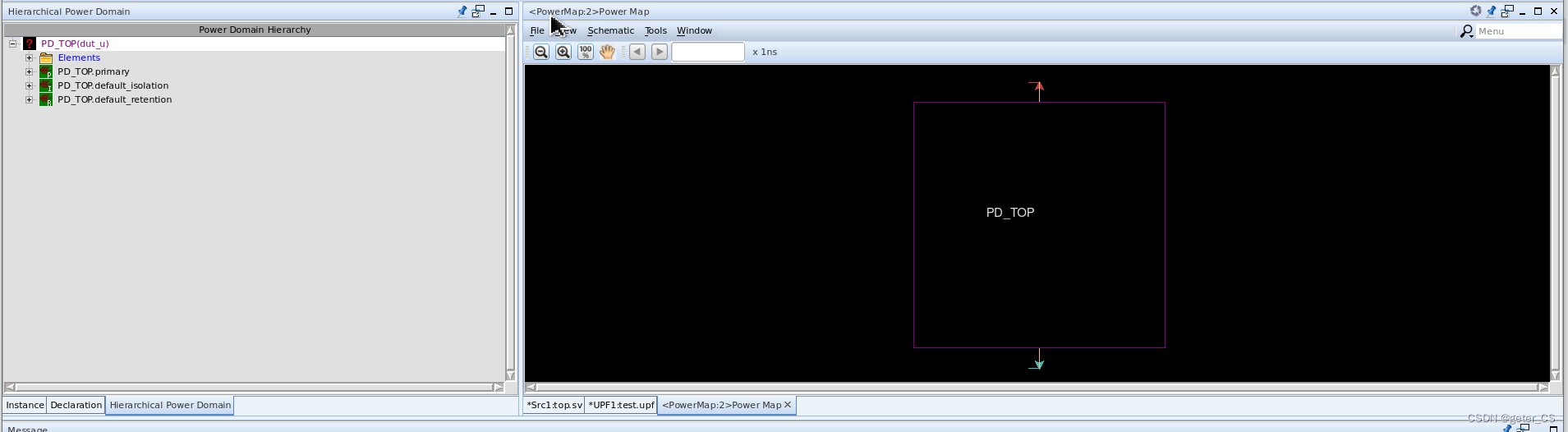
create_power_domain PD_TOP -include_scope运行结果:

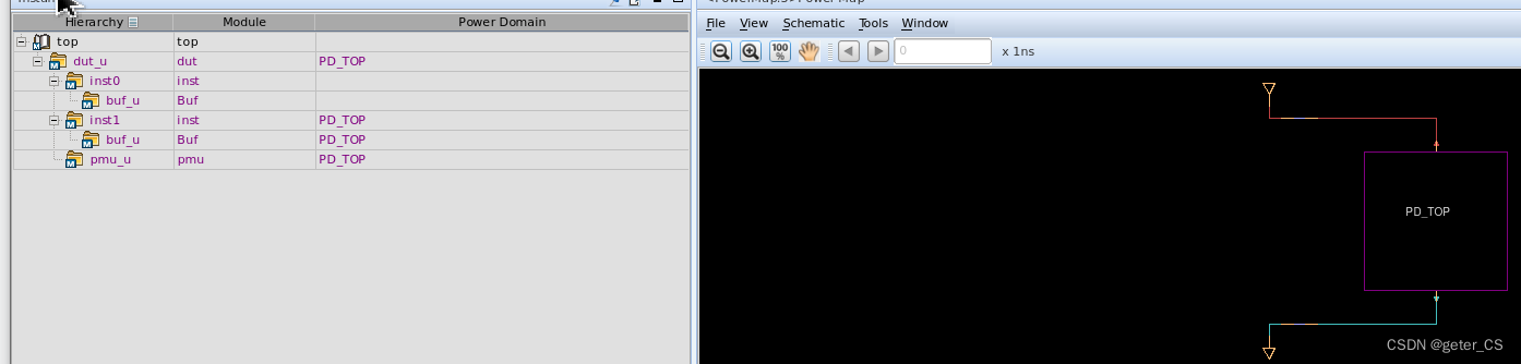
verdi结果中,在full power map窗口中可以看见只有一个电压域被定义,并且其power和ground都还没有定义:
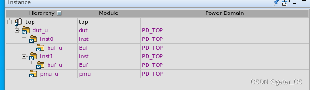
verdi的instance窗口就会显示出各个instance所属于的domain:
(2)将power domain的power和ground加上。
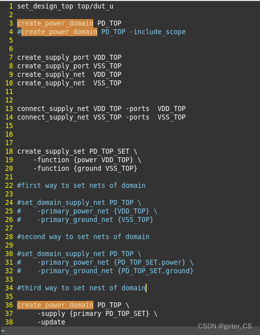
这里给power domain加上power和ground的方式,这里总结有三种。
第一种是通过 set domain_supply_net直接将对应的net设置给power domain。
第二种是通过 set domain_supply_net并使用supply_set句柄设置给power domain。
第三种是通过create_power_domain的-supply选项来直接设置supply_set。(每定义一个power domain 都会自动生成对应三个supply_set: primary ,default_isolation,default_retention-[1] )
下面upf.test内容三种方式都列举了,注意-update的使用,由于前面已经定义了PD_TOP,所以这里要加上-update选项:
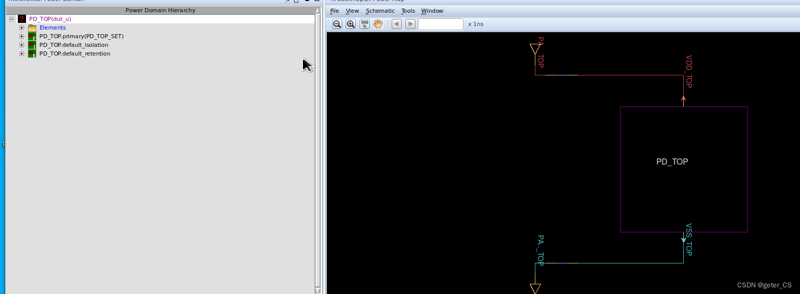
运行结果verdi ,可以看见power domain的power和ground都加上了。
(3)-elements和-exclude_elements使用。
可以这两个选项用来设置此power domain的作用范围。
如下upf.test,将create_power_domain加上-element { . }将当前的所在的scope设置为这个power domain(当然不使用也可以,因为默认是将当前的所在的scope,设置为这个power domain,当前就是top/dut_u,当然也作用于里面各层的instance)。并使用-exclude_elements {inst0}将inst0排除在外 :
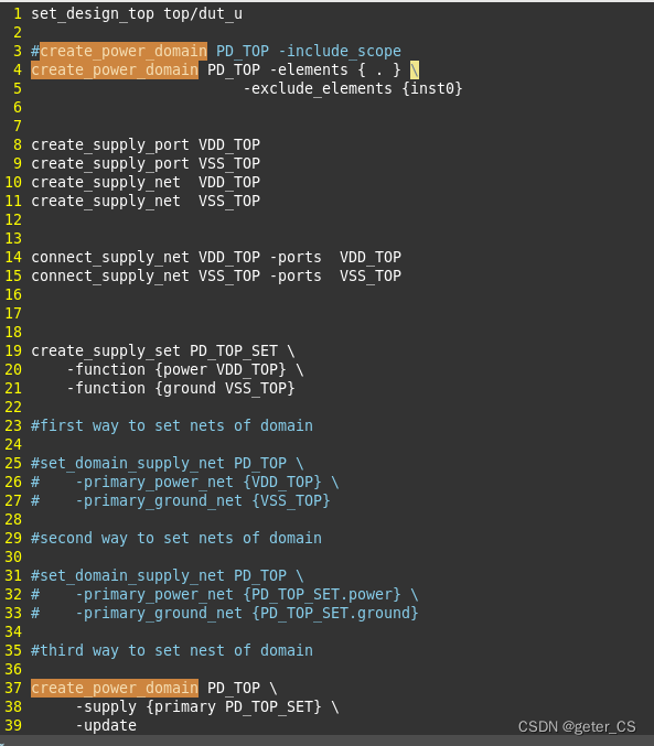
仿真结果如下,可以看见inst0已经不属于PD_TOP了:
(3)定义多个power domain.
举个例子定义两个power domain。test.upf内容如下。
set_design_top top/dut_u

#create_power_domain PD_TOP -include_scope
create_power_domain PD_TOP -elements {.} \
                -exclude_elements {inst0}

create_supply_port VDD_TOP
create_supply_port VSS_TOP
create_supply_net  VDD_TOP
create_supply_net  VSS_TOP

connect_supply_net VDD_TOP -ports VDD_TOP
connect_supply_net VSS_TOP -ports VSS_TOP

create_supply_set PD_TOP_SET \
    -function {power VDD_TOP} \
    -function {power VSS_TOP}

create_power_domain PD_TOP \
    -supply {primary PD_TOP_SET} \
    -update

#PD0
set_scope inst0

create_power_domain PD0 -elements {.}

create_supply_port VDD0
create_supply_port VSS0

create_supply_net VDD0
create_supply_net VSS0

connect_supply_net VDD0 -ports VDD0
connect_supply_net VSS0 -ports VSS0

create_supply_set PD0_SET \
    -function {power VDD0}  \
    -function {ground VSS0}

create_power_domain PD0 \
    -supply {primary PD0_SET} \
    -update
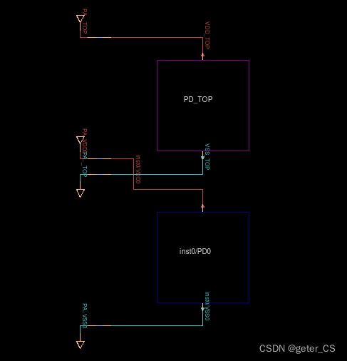
仿真结果,power map如下,注意上面upf中使用了set_scope,所以此时新定义的net VDD0 VSS0,port VDD0 VSS0都是在scope inst0下的:
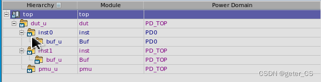
此时instance上显示出两个power domain:
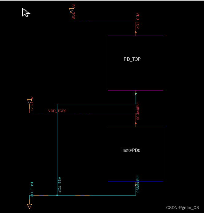
两个domain的power是可以不一样的,但是VSS可以是一样的,所以可以将两个domain的VSS连接起来,并且将PD0的power从外面接进去。在upf.test最后面增加两句,并使用VDD_TOP0 net和PD0的inst0/VDD0 port相接。其中set_scope .. 返回 parent scope。
set_design_top top/dut_u

#create_power_domain PD_TOP -include_scope
create_power_domain PD_TOP -elements {.} \
                -exclude_elements {inst0}

create_supply_port VDD_TOP
create_supply_port VSS_TOP
create_supply_net  VDD_TOP
create_supply_net  VSS_TOP

connect_supply_net VDD_TOP -ports VDD_TOP
connect_supply_net VSS_TOP -ports VSS_TOP

create_supply_set PD_TOP_SET \
    -function {power VDD_TOP} \
    -function {power VSS_TOP}

create_power_domain PD_TOP \
    -supply {primary PD_TOP_SET} \
    -update


create_supply_port VDD_TOP0
create_supply_net  VDD_TOP0
connect_supply_net VDD_TOP0 -ports VDD_TOP0

#PD0
set_scope inst0

create_power_domain PD0 -elements {.}

create_supply_port VDD0
create_supply_port VSS0

create_supply_net VDD0
create_supply_net VSS0

connect_supply_net VDD0 -ports VDD0
connect_supply_net VSS0 -ports VSS0

create_supply_set PD0_SET \
    -function {power VDD0}  \
    -function {ground VSS0}

create_power_domain PD0 \
    -supply {primary PD0_SET} \
    -update


set_scope ..

connect_supply_net VSS_TOP -ports inst0/VSS0
connect_supply_net VDD_TOP0 -ports inst0/VDD0
仿真结果的power map中两个VSS就会连接在一起,并且PD0的power从外层引进去的。结果如下。
参考[0]:IEEE 1801-2015 IEEE Standard for Design and Verification of Low-Power, Energy-Aware Electronic Systems
verdi版本:R-2020.12-SP2
vcs版本: Q-2020.03-SP2
参考[1]: VCS Native Low Power (NLP)User Guide.


 1514
1514

 被折叠的 条评论
为什么被折叠?
被折叠的 条评论
为什么被折叠?
 到【灌水乐园】发言


