


相关宏和变量
#define LED_PIN         GPIO_NUM_3
#define LEDC_CHANNEL    LEDC_CHANNEL_0
#define LEDC_TIMER      LEDC_TIMER_0
#define LEDC_MODE       LEDC_LOW_SPEED_MODE
#define LEDC_DUTY_RES   LEDC_TIMER_13_BIT  // 2^13 = 8192级亮度
#define LEDC_FREQUENCY  5000              // 5kHz频率

//呼吸灯效果
int direction = 1;  // 1: 渐亮, -1: 渐暗
int duty = 0;
1.通过ledc_timer_config_t配置PWM参数
下面是结构体源码
/**
 * @brief Configuration parameters of LEDC timer for ledc_timer_config function
 */
typedef struct {
    ledc_mode_t speed_mode;                /*!< LEDC speed speed_mode, high-speed mode (only exists on esp32) or low-speed mode */
    ledc_timer_bit_t duty_resolution;      /*!< LEDC channel duty resolution */
    ledc_timer_t  timer_num;               /*!< The timer source of channel (0 - LEDC_TIMER_MAX-1) */
    uint32_t freq_hz;                      /*!< LEDC timer frequency (Hz) */
    ledc_clk_cfg_t clk_cfg;                /*!< Configure LEDC source clock from ledc_clk_cfg_t.
                                                Note that LEDC_USE_RC_FAST_CLK and LEDC_USE_XTAL_CLK are
                                                non-timer-specific clock sources. You can not have one LEDC timer uses
                                                RC_FAST_CLK as the clock source and have another LEDC timer uses XTAL_CLK
                                                as its clock source. All chips except esp32 and esp32s2 do not have
                                                timer-specific clock sources, which means clock source for all timers
                                                must be the same one. */
    bool deconfigure;                      /*!< Set this field to de-configure a LEDC timer which has been configured before
                                                Note that it will not check whether the timer wants to be de-configured
                                                is binded to any channel. Also, the timer has to be paused first before
                                                it can be de-configured.
                                                When this field is set, duty_resolution, freq_hz, clk_cfg fields are ignored. */
} ledc_timer_config_t;
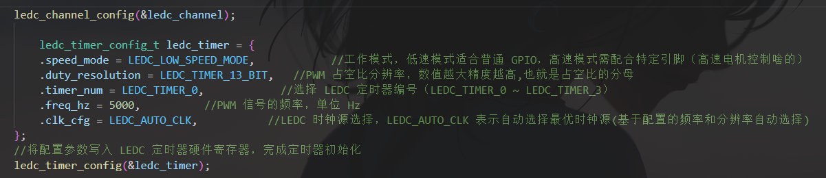
下面是配置
    // 定义 LEDC 定时器配置结构体,用于设置 PWM 信号的“时间基准”(频率、精度等)
    ledc_timer_config_t ledc_timer = {
        .speed_mode = LEDC_MODE,          // LEDC 工作模式(如 LEDC_LOW_SPEED_MODE/LEDC_HIGH_SPEED_MODE)
                                          // 低速模式适合普通 GPIO,高速模式需配合特定引脚,由宏定义指定
        .duty_resolution = LEDC_DUTY_RES, // PWM 占空比分辨率(单位:bit)
                                          // 例:若设为 13bit,占空比范围是 0~2^13-1=8191(数值越大精度越高)
        .timer_num = LEDC_TIMER,          // 选择 LEDC 定时器编号(如 LEDC_TIMER_0 ~ LEDC_TIMER_3)
                                          // 每个定时器可对应多个通道,实现多路 PWM 输出
        .freq_hz = LEDC_FREQUENCY,        // PWM 信号的频率(单位:Hz)
                                          // 例:设为 500Hz,即 PWM 周期为 2ms,人眼无闪烁感
        .clk_cfg = LEDC_AUTO_CLK,         // LEDC 时钟源选择(LEDC_AUTO_CLK 表示自动选择最优时钟源)
                                          // 也可手动指定(如 LEDC_USE_APB_CLK),自动模式更便捷
    };
    // 调用 API 将配置参数写入 LEDC 定时器硬件寄存器,完成定时器初始化
    ledc_timer_config(&ledc_timer);
2.通过ledc_channel_config_t配置PWM通道
结构体源码
/**
 * @brief Configuration parameters of LEDC channel for ledc_channel_config function
 */
typedef struct {
    int gpio_num;                   /*!< the LEDC output gpio_num, if you want to use gpio16, gpio_num = 16 */
    ledc_mode_t speed_mode;         /*!< LEDC speed speed_mode, high-speed mode (only exists on esp32) or low-speed mode */
    ledc_channel_t channel;         /*!< LEDC channel (0 - LEDC_CHANNEL_MAX-1) */
    ledc_intr_type_t intr_type;     /*!< configure interrupt, Fade interrupt enable  or Fade interrupt disable */
    ledc_timer_t timer_sel;         /*!< Select the timer source of channel (0 - LEDC_TIMER_MAX-1) */
    uint32_t duty;                  /*!< LEDC channel duty, the range of duty setting is [0, (2**duty_resolution)] */
    int hpoint;                     /*!< LEDC channel hpoint value, the range is [0, (2**duty_resolution)-1] */
    ledc_sleep_mode_t sleep_mode;   /*!< choose the desired behavior for the LEDC channel in Light-sleep */
    struct {
        unsigned int output_invert: 1;/*!< Enable (1) or disable (0) gpio output invert */
    } flags;                        /*!< LEDC flags */

} ledc_channel_config_t;
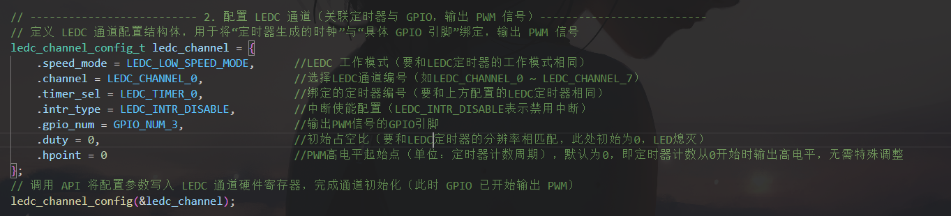
配置
    // 定义 LEDC 通道配置结构体,用于将“定时器生成的时钟”与“具体 GPIO 引脚”绑定,输出 PWM 信号
    ledc_channel_config_t ledc_channel = {
        .speed_mode = LEDC_MODE,          // 必须与定时器的工作模式一致(低速/高速模式需匹配)
        .channel = LEDC_CHANNEL,          // 选择 LEDC 通道编号(如 LEDC_CHANNEL_0 ~ LEDC_CHANNEL_7)
                                          // 一个定时器可对应多个通道,实现“同一频率、不同占空比”的多路 PWM
        .timer_sel = LEDC_TIMER,          // 绑定的定时器编号(需与上方配置的 LEDC_TIMER 一致)
                                          // 表示该通道使用此定时器生成的 PWM 基准时钟
        .intr_type = LEDC_INTR_DISABLE,   // 中断使能配置(LEDC_INTR_DISABLE 表示禁用中断)
                                          // 若需占空比更新完成后触发中断,可设为 LEDC_INTR_ENABLE
        .gpio_num = LED_PIN,              // 输出 PWM 信号的 GPIO 引脚(如 GPIO_NUM_2)
                                          // 需确保该引脚支持 LEDC 功能(参考芯片手册的引脚功能表)
        .duty = 0,                        // 初始占空比(需与定时器分辨率匹配,此处初始为 0,LED 熄灭)
                                          // 例:分辨率 13bit 时,0 表示占空比 0%(全灭),8191 表示 100%(全亮)
        .hpoint = 0                       // PWM 高电平起始点(单位:定时器计数周期)
                                          // 默认为 0,即定时器计数从 0 开始时输出高电平,无需特殊调整
    };
    // 调用 API 将配置参数写入 LEDC 通道硬件寄存器,完成通道初始化(此时 GPIO 已开始输出 PWM)
    ledc_channel_config(&ledc_channel);
实现
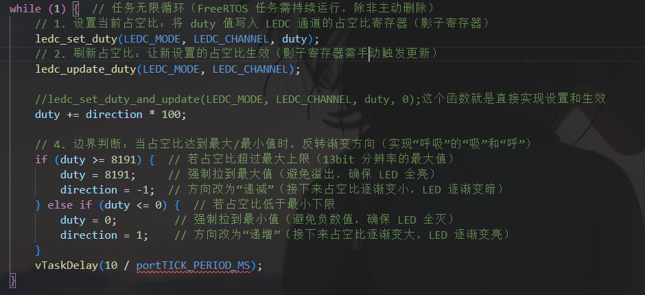
    while (1) {
        ledc_set_duty(LEDC_MODE, LEDC_CHANNEL, duty);

        ledc_update_duty(LEDC_MODE, LEDC_CHANNEL);

        duty += direction * 100;

        if (duty >= 8191) {
            duty = 8191;
            direction = -1;
        }
        else if (duty <= 0) {
            duty = 0;
            direction = 1;
        }

        vTaskDelay(10 / portTICK_PERIOD_MS);
    }
流程
一:先配置目标PWM的参数
二:然后配置定时器的PWM输出到哪个引脚
三:编写呼吸灯的渐变
四:实现
#include <stdio.h>
#include "driver/ledc.h"
#include "esp_log.h"

// 硬件配置定义
#define LED_PIN         GPIO_NUM_3
#define LEDC_CHANNEL    LEDC_CHANNEL_0
#define LEDC_TIMER      LEDC_TIMER_0
#define LEDC_MODE       LEDC_LOW_SPEED_MODE
#define LEDC_DUTY_RES   LEDC_TIMER_13_BIT  // 2^13 = 8192级亮度
#define LEDC_FREQUENCY  5000               // 5kHz频率

static const char *TAG = "BREATHE_LED";

/**
 * @brief 应用程序入口
 */
void app_main(void)
{
    printf("ESP32 Breathe LED Demo Started!\n");
    printf("LED Pin: GPIO %d\n", LED_PIN);
    printf("PWM Frequency: %d Hz\n", LEDC_FREQUENCY);
    printf("PWM Resolution: 13-bit (0-8191)\n");

    // -------------------------- 1. 配置 LEDC 定时器 ---------------------------
    ledc_timer_config_t ledc_timer = {
        .speed_mode = LEDC_MODE,
        .duty_resolution = LEDC_DUTY_RES,
        .timer_num = LEDC_TIMER,
        .freq_hz = LEDC_FREQUENCY,
        .clk_cfg = LEDC_AUTO_CLK,
    };
    ESP_ERROR_CHECK(ledc_timer_config(&ledc_timer));

    // -------------------------- 2. 配置 LEDC 通道 ---------------------------
    ledc_channel_config_t ledc_channel = {
        .speed_mode = LEDC_MODE,
        .channel = LEDC_CHANNEL,
        .timer_sel = LEDC_TIMER,
        .intr_type = LEDC_INTR_DISABLE,
        .gpio_num = LED_PIN,
        .duty = 0,
        .hpoint = 0
    };
    ESP_ERROR_CHECK(ledc_channel_config(&ledc_channel));

    ESP_LOGI(TAG, "Breathe LED initialized on GPIO %d", LED_PIN);

    // 呼吸灯变量
    int direction = 1;  // 1: 渐亮, -1: 渐暗
    int duty = 0;

    // -------------------------- 3. 呼吸灯主循环 ---------------------------
    while (1) {
        // 设置占空比并立即生效(推荐使用这个函数)
        ESP_ERROR_CHECK(ledc_set_duty_and_update(LEDC_MODE, LEDC_CHANNEL, duty, 0));

        // 调整占空比
        duty += direction * 100;

        // 边界检查
        if (duty >= 8191) {
            duty = 8191;
            direction = -1;
            printf("Reached maximum brightness, starting to fade out...\n");
        } else if (duty <= 0) {
            duty = 0;
            direction = 1;
            printf("Reached minimum brightness, starting to fade in...\n");
        }

        // 简单的延时(使用空循环实现,不依赖FreeRTOS)
        // 注意:这种方法会阻塞CPU,在实际应用中建议使用vTaskDelay
        for (volatile int i = 0; i < 10000; i++) {
            // 空循环延时
        }
    }
}
说明
esp32的ledc库专门负责PWM信号的生成


 1573
1573

 被折叠的 条评论
为什么被折叠?
被折叠的 条评论
为什么被折叠?
 到【灌水乐园】发言


