


实验内容
一. 实验目标:
学习 Quartus 、Platform Designer、Nios-II SBT 的基本操作;初步了解 SOPC 的开发流程,基本掌握 Nios-II 软核的定制方法;掌握 Nios-II 软件的开发流程,软件的基本调试方法。
二. 实验过程:
1、完成以下实验:
1) 在DE2-115开发板上分别用 Verilog和 Nios软件编程两种方式完成LED流水灯显示,理解两种方式的差异;
2) 分别用Verilog和Nios软件编程, 实现DE2-115开发板串口输出“Hello Nios-II”字符到笔记本电脑串口助手。
3)分别在DE2-115开发板和树莓派上编写串口通信程序, 实现树莓派串口指令对FPGA板子上的流水灯程序的控制,控制方式自定。
一、Verilog点亮流水灯
1、创建quartus工程
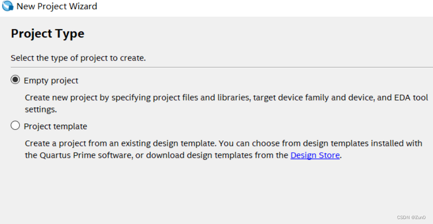
打开quartus -> New Project Wizard
设置文件放置位置、文件名
NEXT
Next
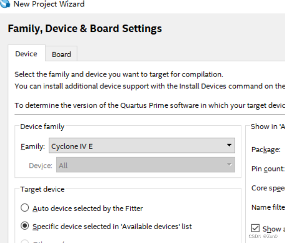
选择芯片EP4E115F29C7 -> Finish
2、编写Verilog文件
module led_flow #(parameter TIME_0_5S = 25_000_000)(
input sys_clk ,
input sys_rst_n ,
output reg [7:0] led
);
reg [24:0] cnt ;
wire add_cnt ;
wire end_cnt ;
reg [2:0] cnt1;
wire add_cnt1;
wire end_cnt1;
always @(posedge sys_clk or negedge sys_rst_n)begin
if(!sys_rst_n) begin
cnt <= 25'b0;
end
else if(add_cnt) begin
if(end_cnt) begin
cnt <= 25'b0;
end
else begin
cnt <= cnt+1'b1;
end
end
else begin
cnt <= cnt;
end
end
// 异步复位
always @(posedge sys_clk or negedge sys_rst_n) begin
if(!sys_rst_n)begin
cnt1 <= 3'b0;
end
else if(add_cnt1) begin
if(end_cnt1)begin
cnt1 <= 3'b0;
end
else begin
cnt1 <= cnt1 + 1'b1;
end
end
end
always @(posedge sys_clk or negedge sys_rst_n)begin
if(!sys_rst_n)begin
led <= 8'b0;
end
else begin
case (cnt1)
3'b000 : led <= 8'b0000_0001;
3'b001 : led <= 8'b0000_0010;
3'b010 : led <= 8'b0000_0100;
3'b011 : led <= 8'b0000_1000;
3'b100 : led <= 8'b0001_0000;
3'b101 : led <= 8'b0010_0000;
3'b110 : led <= 8'b0100_0000;
3'b111 : led <= 8'b1000_0000;
default: led <= led;
endcase
end
end
assign add_cnt = 1'b1;
assign end_cnt = add_cnt && cnt == TIME_0_5S - 1;
assign add_cnt1 = (cnt == TIME_0_5S-1);
assign end_cnt1 = add_cnt1 && cnt1 == 3'b111;
endmodule
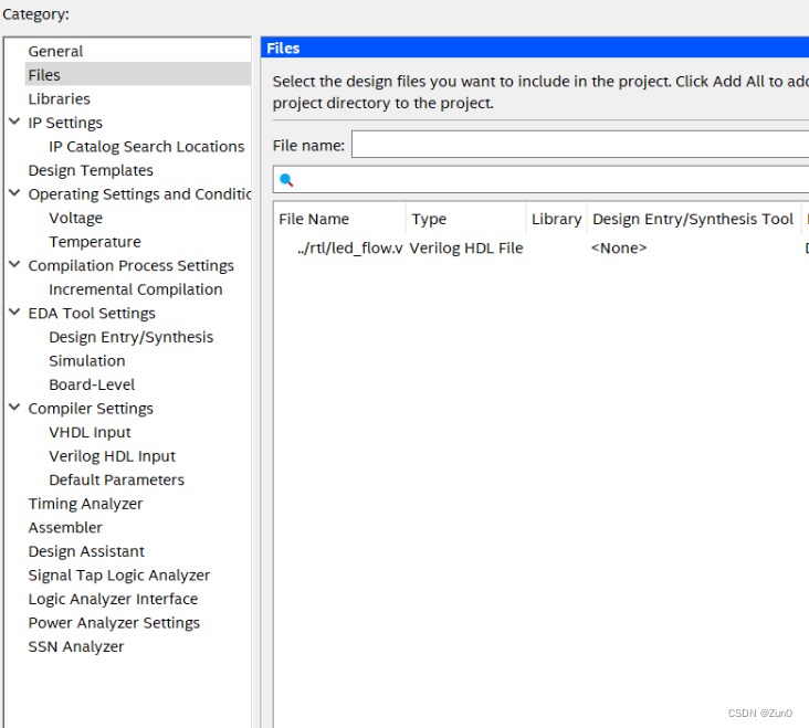
3、将Verilog文件导入刚新建的Quartus文件中编译烧录
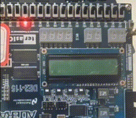
4、结果
二、Nois软件编程点亮流水灯
1、创建quartus工程
打开quartus -> New Project Wizard
设置文件放置位置、文件名
NEXT
Next
选择芯片EP4E115F29C7 -> Finish
2、添加qip文件
参考基于Nios-II实现流水灯_quartus 添加qip文件-优快云博客
三、Verilog实现串口
1、创建项目
参考一
2、代码
uart.tx
//波特率为115200bps,即每秒传送115200bit的数据,传送1bit数据需要434个时钟周期
//tx内部是并行数据,需要串行传出去,一般数据格式是1bit的起始位,8bit的数据位,1bit的停止位
//所以需要一个8bit的计数器,计算传送了多少个bit,起始位是低电平有效,停止位是持续的高电平
//需要接收8bit的数据
//需要1bit的传送出去
module uart_tx(
input clk ,
input rst_n ,
//in
input [7:0] din ,//要发送的数据
input din_vld,//数据有效
//out
output reg [3:0] cnt_byte,//现在输出第几个byte了
output reg tx //串口数据
);
parameter Baud = 434;
//波特率计时器
reg [8:0] cnt_baud ;
wire add_cnt_baud ;
wire end_cnt_baud ;
reg flag;
always @(posedge clk or negedge rst_n)begin
if(!rst_n)begin
cnt_baud <= 0;
end
else if(add_cnt_baud)begin
if(end_cnt_baud)begin
cnt_baud <= 0;
end
else begin
cnt_baud<=cnt_baud+1;
end
end
else begin
cnt_baud <= cnt_baud;
end
end
assign add_cnt_baud = flag;
assign end_cnt_baud = add_cnt_baud && cnt_baud == Baud - 1;
always @(posedge clk or negedge rst_n)begin
if(!rst_n)begin
flag <= 1'b0;
end
else if(din_vld)begin
flag <= 1'b1;
end
else if(end_cnt_bit)begin
flag <= 1'b0;
end
else begin
flag <= flag;
end
end
//波特率计数完成,就可以发送下一个bit
//表示需要把第几位发送出去
reg [3:0] cnt_bit;//最多是8
wire add_cnt_bit;
wire end_cnt_bit;
always @(posedge clk or negedge rst_n)begin
if(!rst_n)begin
cnt_bit <= 0;
end
else if(add_cnt_bit)begin
if(end_cnt_bit)begin
cnt_bit <= 0;
end
else begin
cnt_bit <= cnt_bit + 1;
end
end
else begin
cnt_bit <= cnt_bit;
end
end
assign add_cnt_bit = end_cnt_baud;
assign end_cnt_bit = add_cnt_bit && cnt_bit == 8;
//发送到第几个字符,总共要发15个字符
wire add_cnt_byte ;
wire end_cnt_byte ;
always @(posedge clk or negedge rst_n)begin
if(!rst_n)begin
cnt_byte <= 0;
end
else if(add_cnt_byte)begin
if(end_cnt_byte)begin
cnt_byte <= 0;
end
else begin
cnt_byte <= cnt_byte + 1;
end
end
else begin
cnt_byte <= cnt_byte;
end
end
assign add_cnt_byte = end_cnt_bit;//发送完8bit后
assign end_cnt_byte = add_cnt_byte && cnt_byte == 14;
//发送数据的逻辑,先加上起始位
reg [8:0] data ;
always @(posedge clk or negedge rst_n)begin
if(!rst_n)begin
data <= 9'h1ff;
end
else if(din_vld)begin
data <= {din,1'b0}; //数据加上起始位
end
else begin
data <= data;
end
end
//并行转串行逻辑
always @(posedge clk or negedge rst_n)begin
if(!rst_n)begin
tx <= 0;
end
else if(cnt_baud == 1)begin //每发送完1bit,就发送一个tx;
tx <= data[cnt_bit];//LSP,低位先发
end
else if(end_cnt_bit)begin
//处理停止位
tx <= 1'b1;
end
else begin
tx <= tx;
end
end
endmodule
test.v
module test(
input clk ,
input rst_n ,
input wire [3:0] cnt_byte,//现在输出第几个byte了
output reg dout_vld,//表示200us间隔实现
output reg [7:0] led_data//表示输出的数据
);
//总共需要发送15个字符,所以需要15的计数器
//200us计数器
parameter TIME_200uS = 1_000_0;
reg [13:0] cnt_200uS;
wire add_cnt_200uS;
wire end_cnt_200uS;
always @(posedge clk or negedge rst_n)begin
if(!rst_n)begin
cnt_200uS <= 0;
end
else if(add_cnt_200uS)begin
if(end_cnt_200uS)begin
cnt_200uS <= 0;
end
else begin
cnt_200uS <= cnt_200uS + 1;
end
end
else begin
cnt_200uS <= 0;
end
end
assign add_cnt_200uS = 1'b1;
assign end_cnt_200uS = add_cnt_200uS && cnt_200uS == TIME_200uS - 1;
//定义输出数据
//Hello Nios-II到串口
always @(posedge clk or negedge rst_n)begin
if(!rst_n)begin
dout_vld <= 1'b0;
end
else if(end_cnt_200uS)begin
dout_vld <= 1'b1;
case(cnt_byte)
0 : led_data = 8'b01001000;//H
1 : led_data = 8'b01100101;//e
2 : led_data = 8'b01101100;//l
3 : led_data = 8'b01101100;//l
4 : led_data = 8'b01101111;//o
5 : led_data = 8'b00100000;//space
6 : led_data = 8'b01001110;//N
7 : led_data = 8'b01101001;//i
8 : led_data = 8'b01101111;//o
9 : led_data = 8'b01110011;//s
10 : led_data = 8'b00101101;//-
11 : led_data = 8'b01001001;//I
12 : led_data = 8'b01001001;//I
13 : led_data = 8'b00001101;//\r
14 : led_data = 8'b00001010;//\n
default : led_data = 8'b0;
endcase
end
else begin
dout_vld <= 1'b0;
end
end
endmodule
top.v
module top(
input clk ,
input rst_n ,
output tx
);
wire [7:0] led_data ;
wire [3:0] cnt_byte ;
wire din_vld ;
uart_tx inst_uart_tx(
.clk (clk ),
.rst_n (rst_n ),
//in
.din (led_data),//如果串口占用时,uart_data
.din_vld (din_vld),
//out
.cnt_byte (cnt_byte),
.tx (tx )
);
test inst_test(
.clk (clk ),
.rst_n (rst_n ),
//in
.cnt_byte (cnt_byte),
//out
.led_data (led_data ),
.dout_vld (din_vld)
);
endmodule
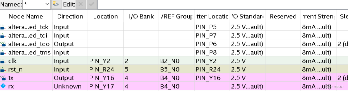
3、配置引脚
4、结果
四、NiosII实现串口
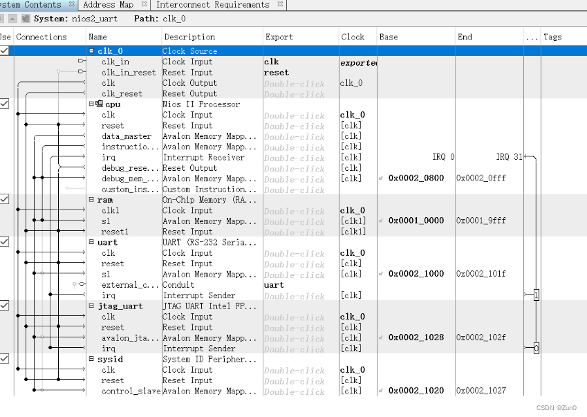
1、sopc硬件设计
2、 top.v
module nios2_uart_top(
input clk,
input rst_n,
input rxd,
output txd
);
nios2_uart u0 (
.clk_clk (clk), // clk.clk
.reset_reset_n (rst_n), // reset.reset_n
.uart_rxd (rxd), // uart.rxd
.uart_txd (txd) // .txd
);
endmodule
3、软件部分
#include <stdio.h>
#include "unistd.h"
#include "system.h"
#include "alt_types.h"
#include "altera_avalon_uart_regs.h"
#include "sys\alt_irq.h"
/*
* 串口发送字符串函数
* */
/*
void Uart_sendString(char *data, unsigned int len)
{
alt_u8 i;
for(i=0;i<len;i++)
{
IOWR_ALTERA_AVALON_UART_TXDATA(UART_BASE, data[i]); //数据发送完,将TRDY置为1
while((IORD_ALTERA_AVALON_UART_STATUS(UART_BASE) & 0x40)!=0x40); //判断数据(TRDY==1)是否发送完毕
}
}
*/
int main()
{
char *str = "hello Niosii!\r\n";
while(1){
alt_u8 j;
for(j = 0; j < 17; j++){
IOWR_ALTERA_AVALON_UART_TXDATA(UART_BASE, str[j]); //数据发送完,将TRDY置为1
while((IORD_ALTERA_AVALON_UART_STATUS(UART_BASE) & 0x40)!=0x40); //判断数据(TRDY==1)是否发送完毕
}
int i = 0;
while(i<500000)
{
i++;
}
}
return 0;
}
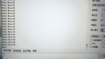
4、结果


 674
674

 被折叠的 条评论
为什么被折叠?
被折叠的 条评论
为什么被折叠?
 到【灌水乐园】发言


