


借鉴该博文
matlab代码修改过后:
用matlab输入一组配置滤波器FIR IP核的系数:
% clc;
% clear;
% alpha = 0.15; % 滚降系数
% span = 6; % 表示截断的符号范围。
% inte = 16; % 内插系数
% % rcosdesign用于设计根升余弦滤波器的函数。
% hrc = rcosdesign(alpha, span, inte, 'sqrt');
% % 量化系数到16位整数
% hrc_q = fix(hrc./max(hrc)*(2^15-1)); % 量化系数16
%
% % 确保所有系数都是非负的,并且适合16位整数的范围
% hrc_q = max(hrc_q, 0);
% hrc_q = min(hrc_q, 2^15-1);
%
% % 打开文件
% file_path = "D:/L/vivado project/qpsk_sim/qpsk_sim.srcs/sources_1/ip/fir_hrc_16.coe";
% f = fopen(file_path, 'w');
% % 写入头信息
% fprintf(f, '; Example of a Distributed Arithmetic (DA) FIR Filter .COE file\n');
% fprintf(f, '; with hex coefficients, and 16-bit coefficients.\n');
% fprintf(f, 'Radix = 16;\n');
% fprintf(f, 'CoefData =\n');
% % 写入系数
% for i = 1:length(hrc_q)
%     % 将整数转换为十六进制字符串,并去除前缀'0x'
%     hex_str = dec2hex(hrc_q(i), 6); % 转换为6位十六进制数
%     fprintf(f, '%s, ', hex_str);
%     % 每8个系数换行,这是可选的,为了提高可读性
%     if mod(i, 8) == 0
%         fprintf(f, '\n');
%     end
% end
% % 在文件末尾添加分号
% fprintf(f, ';\n');
% fclose(f);
再用matlab产生一组随机输入数据:
num_samples = 4096;

% 生成随机一位二进制数据
data_send_mem = randi([0 1], 1, num_samples);

% 将二进制数据写入文本文件
file_name = 'D:\L\vivado project\qpsk_sim\data_send_mem.txt';
file_id = fopen(file_name, 'w');

% 写入数据
for i = 1:num_samples
    fprintf(file_id, '%d\n', data_send_mem(i));
    % 每个比特后不加空格或换行,以生成连续的比特流
end

% 关闭文件
fclose(file_id);

disp(['Data has been written to ', file_name]);
FIR\DDS\MUTIPILIER IP核配置参照上面链接
TB文件:
module qpsk_tb( );
//变量声明
    reg clk;
    reg rst;
    wire [1:0]data_send;
    wire [35:0] qpsk;
//例化BPSK生成模块
    QPSK_top QPSK_top_inst(
        .clk(clk),
        .rst(rst),
        .data_send(data_send[1:0]),
        .qpsk( qpsk[35:0])
    );
//激励时钟
    always #10 clk = ~clk;
    reg [0:0] data_send_mem[0:4095];
//初始化变量
    initial
        begin
            clk <= 1'b0;
          //  rst <= 1'b1;
            $readmemh("D:/ryno/ryno/VERILOG_BPSK/QPSK_PRO/data_send.txt",data_send_mem);
            //读文件,读取文件中的输入符号至data_send_mem【“”中放你的提前生成好的随机数据路径】
          //  #20
            rst <= 1'b0;

        end
// //生成测试数据数据(随机产生的)
//     always @(posedge clk)
//     begin
//         if (rst)
//         begin
//             data_send_m <= 1'b00;
//         end

//         else begin
//            data_send_m<= $random();
//         end
//     end
//assign data_send = data_send_m;

    reg [3:0] cnt_16 = 4'd0;
    reg [10:0] cnt_mem = 11'd0;
    always @ (posedge clk) begin
        if(~rst) begin
            cnt_16[3:0] <= cnt_16[3:0] + 4'd1; //在testbench中生成长度为16的计数器,控制输入数据的读取
        end
    end

    always @ (posedge clk) begin
        if(~rst) begin
            if(cnt_16[3:0] == 4'd15) begin
                cnt_mem[10:0] <= cnt_mem[10:0] + 11'd2; //地址,每16个时钟+2,取data_send_mem中的两个输入符号数据
            end
        end
    end

    assign data_send[1:0] = {data_send_mem[cnt_mem+1],data_send_mem[cnt_mem]}; //输入符号即为在存储器中取当前地址的数据


endmodule
top代码:
`timescale 1ns / 1ps
//
// Company:
// Engineer:
//
// Create Date: 2024/03/21 10:48:23
// Design Name:
// Module Name: QPSK_top
// Project Name:
// Target Devices:
// Tool Versions:
// Description:
//
// Dependencies:
//
// Revision:
// Revision 0.01 - File Created
// Additional Comments:
//
//


module QPSK_top(
    input clk,
    input rst,
    input [1:0]data_send,
    output [35:0] qpsk

    );

    wire [1:0]I;
    wire [1:0]Q;
    //对极化 :0——>+1(01)  1——>-1(11)
    assign I ={data_send[0],1'b1};
    assign Q ={data_send[1],1'b1};


    reg [3:0] cnt_16  = 4'b00;//16计数器,内插系数是16(时钟速率是符号速率的4倍)
    always @(posedge clk)
    begin
        if(rst) begin
            cnt_16<=4'b00;
        end else begin
            cnt_16 <= cnt_16+1'b1;
        end
    end

    wire fir_nd; //输入FIR滤波器有效信号
    assign fir_nd = (cnt_16 == 4'd15);


    wire [23:0] I_filtered;
    wire [23:0] Q_filtered;
    wire [15:0]  carry_cos;
    wire [15:0]  carry_sin;
    //I路成形滤波
    rcosfilter rcosfilter_I (
        .aclk(clk),                    // input wire aclk
        .s_axis_data_tvalid(fir_nd),        // 输入I路有效信号
        .s_axis_data_tready(),             // output wire s_axis_data_tready
        .s_axis_data_tdata({6'd0,I[1:0]}), // input wire [7 : 0] s_axis_data_tdata     {6{I[1]}}
        .m_axis_data_tvalid(),             // output wire m_axis_data_tvalid
        .m_axis_data_tdata(I_filtered)     // output wire [23 : 0] m_axis_data_tdata
    );

    //Q路成形滤波
    rcosfilter rcosfilter_Q (
        .aclk(clk),                    // input wire aclk
        .s_axis_data_tvalid(fir_nd),        // 输入Q路有效信号
        .s_axis_data_tready(),             // output wire s_axis_data_tready
        .s_axis_data_tdata({6'd0,Q[1:0]}), // input wire [7 : 0] s_axis_data_tdata
        .m_axis_data_tvalid(),             // output wire m_axis_data_tvalid
        .m_axis_data_tdata(Q_filtered)     // output wire [23 : 0] m_axis_data_tdata
    );

    //产生cos波形
    dds_cos dds_demo_cos_inst (
        .aclk(clk),                    // input wire aclk
        .m_axis_data_tvalid(),             // output wire m_axis_data_tvalid
        .m_axis_data_tdata(carry_cos[15:0])   // output wire [7 : 0] m_axis_data_tdata
    );


    //产生sin波形
    dds_sin dds_demo_sin_inst (
        .aclk(clk),                     // input wire aclk
        .m_axis_data_tvalid(),              // output wire m_axis_data_tvalid
        .m_axis_data_tdata(carry_sin[15:0])     // output wire [7 : 0] m_axis_data_tdata
    );


    wire [35:0] qpsk_i;
    wire [35:0] qpsk_q;
    //I路滤波后与cos载波相乘, 成形滤波结果低位截断、相当于增益降低
    mul_mod mul_mod_I
    (
        .CLK(clk),                      // input wire CLK
        .A(I_filtered[23:0]),               // input wire [19 : 0] A
        .B(carry_cos[11:0]),                 // input wire [7 : 0] B
        .P(qpsk_i[35:0] )                          // output wire [27 : 0] P
    );


    //Q路滤波后与sin载波相乘
    //位宽配置同I路一致
    mul_mod mul_mod_Q
    (
        .CLK(clk),                      // input wire CLK
        .A(Q_filtered[23:0]),               // input wire [19 : 0] A
        .B(carry_sin[11:0]),                 // input wire [7 : 0] B
        .P(qpsk_q[35:0])                          // output wire [27 : 0] P
    );


    //IQ两路信号叠加
    assign qpsk = qpsk_i + qpsk_q;


endmodule
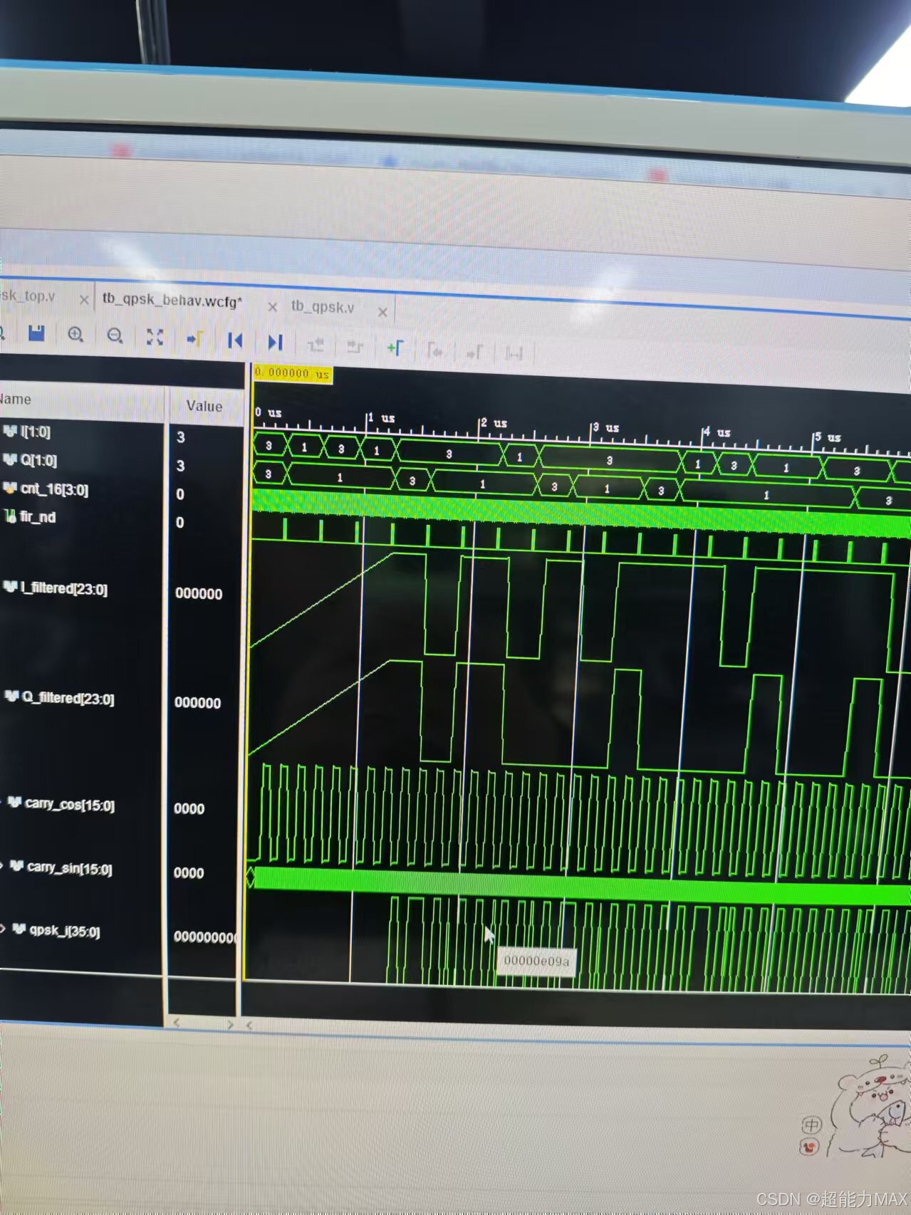
仿真:
滤波器的系数coe文件中前两行要加入这几句配置信息:
; Example of a Distributed Arithmetic (DA) FIR Filter .COE file
; with hex coefficients, and 16-bit coefficients.
Radix = 16;
CoefData =
000000, 000000, 000003, 000253, 0004AF, 0006FE, 000924, 000B08,
000C90, 000DA4, 000E31, 000E28, 000D7D, 000C2E, 000A3C, 0007B0,
00049C, 000116, 000000, 000000, 000000, 000000, 000000, 000000,
000000, 000000, 000000, 000000, 000000, 000000, 000000, 000000,
000000, 00030E, 000C19, 00160A, 0020AE, 002BCF, 00372E, 004289,
004D9E, 005827, 0061E3, 006A96, 007206, 007804, 007C69, 007F18,
007FFF, 007F18, 007C69, 007804, 007206, 006A96, 0061E3, 005827,
004D9E, 004289, 00372E, 002BCF, 0020AE, 00160A, 000C19, 00030E,
000000, 000000, 000000, 000000, 000000, 000000, 000000, 000000,
000000, 000000, 000000, 000000, 000000, 000000, 000000, 000116,
00049C, 0007B0, 000A3C, 000C2E, 000D7D, 000E28, 000E31, 000DA4,
000C90, 000B08, 000924, 0006FE, 0004AF, 000253, 000003, 000000,
000000, ;


 3208
3208

 被折叠的 条评论
为什么被折叠?
被折叠的 条评论
为什么被折叠?
 到【灌水乐园】发言


