


文章目录
前言
局部网络管理除了Autosar Nm,一般还需要特殊的CAN收发器支持。本文介绍TLE9471的局部网络(PN)唤醒的配置
TLE9471参考代码
Infineon提供一个SBC代码参考配置工具,目前最新的需要在Developer Center Launcher中进行安装,
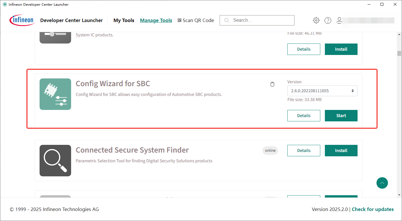
Developer Center Launcher可以从官网进行下载,Developer Center Launcher
配置工具如下: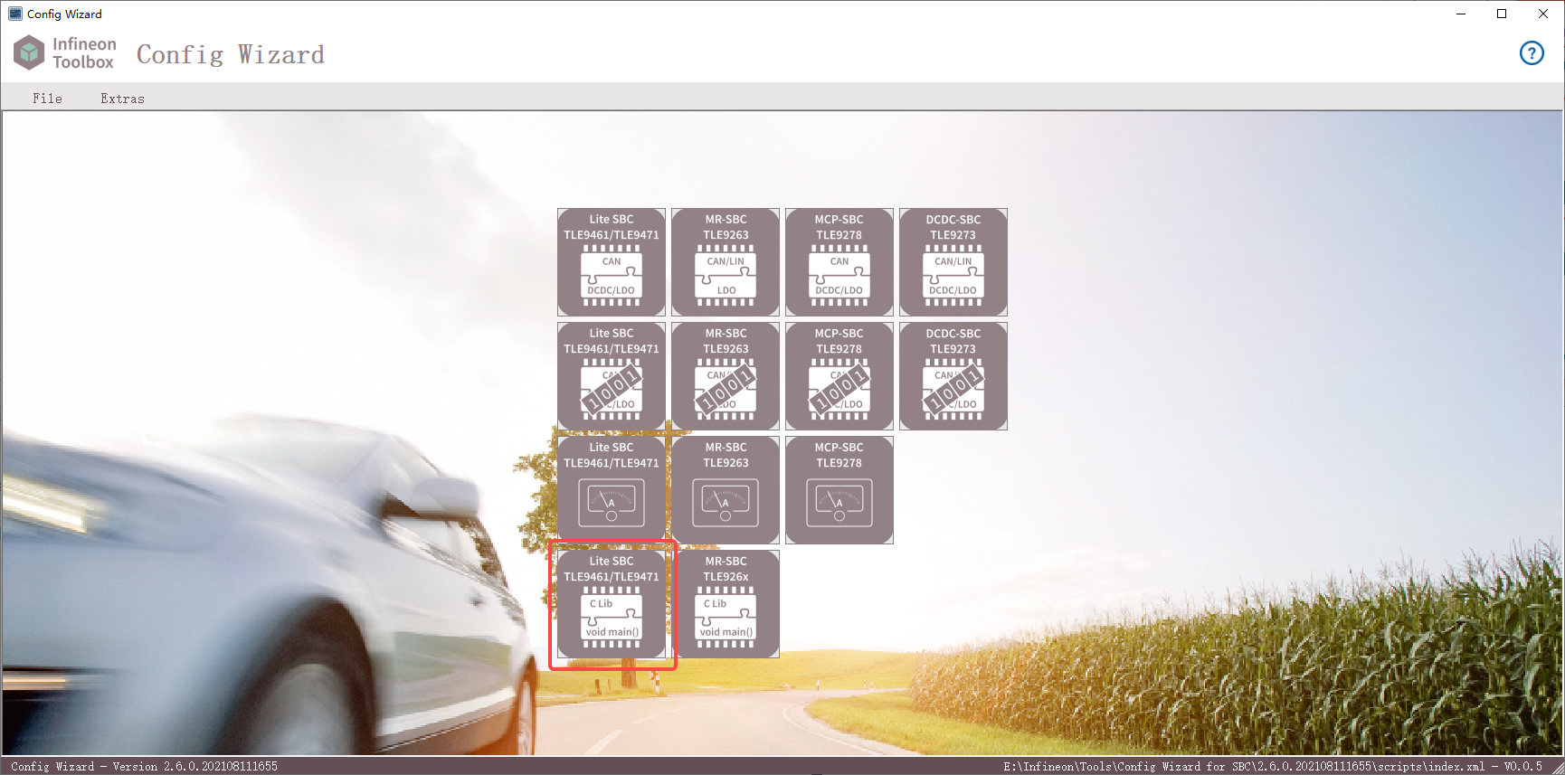
按自己需求后配点Export即可导出参考代码
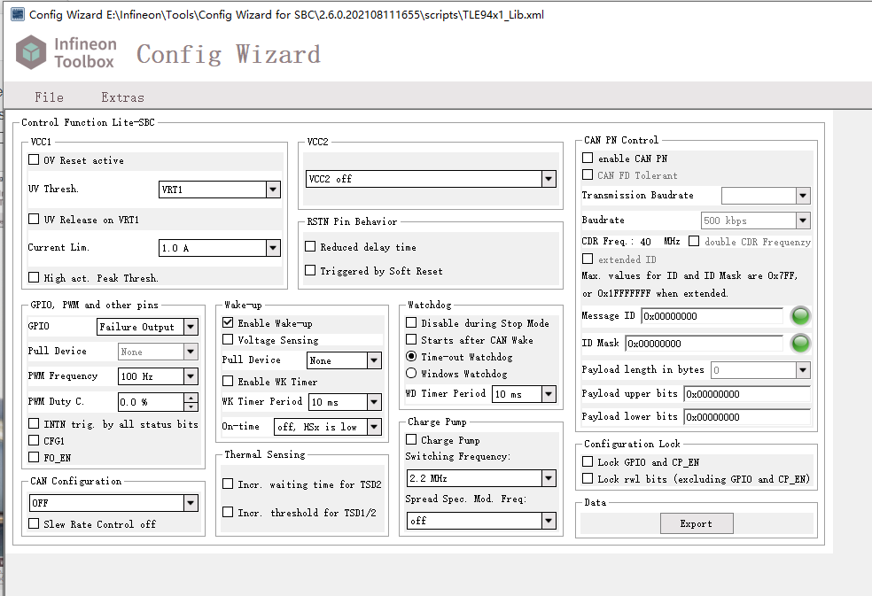
PN配置
PN相关配置如下:
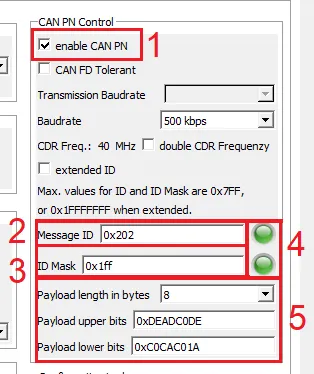
- 启用CAN PN功能。
- 输入需要过滤的CAN ID。
- 配置Mask ID。对于掩码中配置的每一个“1”位,将会进行匹配。如果APP只对一个CAN ID接收,0x7FF可以用作标准掩码
ID或0x1FFFFFFF用于扩展ID。 - 这表明配置的值是否有效。如果显示为红色,表示无法配置ID或掩码
- CAN帧的消息有效载荷长度和有效载荷内容可以在这里配置。
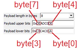
数据字节从SWK_DATA7_CTRL开始,例如,如果发送两个数据字节,它们必须配置在
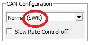
SWK_DATA7_CTRL和SWK_DATA6_CTRL - 请确保将CAN配置设置为包含SWK的CAN模式。
注意:在CANFD网络中,需要启用CANFD Tolerant,具体可以参考之前的文章:TLE9471 CANFD报文异常唤醒ECU问题
初始化
计算ID和MASK ID
判断需要check的ID是否为扩展帧,不过目前网络管理报文都是标准帧ID
/* Check if ID is configured to be extended */
    if((CTRL_SWK_ID0_CTRL & SBC_SWK_ID0_CTRL_IDE_Msk) == SBC_IDE_EXTENDED) {
        /* extended ID */
        uint32 SWK_ID_CTRL = CTRL_SWK_IDx_CTRL << 3;
        uint32 SWK_MASK_ID_CTRL = CTRL_SWK_MASK_IDx_CTRL << 3;

        SWK_ID3_CTRL = (uint8)(SWK_ID_CTRL >> 24);
        SWK_ID2_CTRL = (uint8)(SWK_ID_CTRL >> 16);
        SWK_ID1_CTRL = (uint8)(SWK_ID_CTRL >> 8);
        SWK_ID0_CTRL = (((uint8)(SWK_ID_CTRL >> 1)) & SBC_SWK_ID0_CTRL_ID4_0_Msk) | SBC_IDE_EXTENDED;
        SWK_MASK_ID3_CTRL = (uint8)(SWK_MASK_ID_CTRL >> 24);
        SWK_MASK_ID2_CTRL = (uint8)(SWK_MASK_ID_CTRL >> 16);
        SWK_MASK_ID1_CTRL = (uint8)(SWK_MASK_ID_CTRL >> 8);
        SWK_MASK_ID0_CTRL = (((uint8)(SWK_MASK_ID_CTRL >> 1)) & SBC_SWK_MASK_ID0_CTRL_MASK_ID4_0_Msk);
    } else {
        /* Standard length ID */
        uint16_t SWK_ID_CTRL = CTRL_SWK_IDx_CTRL;
        uint32_t SWK_MASK_ID_CTRL = CTRL_SWK_MASK_IDx_CTRL;

        SWK_ID3_CTRL = (uint8)(SWK_ID_CTRL >> 3);
        SWK_ID2_CTRL = (uint8)(SWK_ID_CTRL << 5);
        SWK_ID1_CTRL = 0x00U;
        SWK_ID0_CTRL = 0x00U;
        SWK_MASK_ID3_CTRL = (uint8)(SWK_MASK_ID_CTRL >> 3);
        SWK_MASK_ID2_CTRL = (uint8)(SWK_MASK_ID_CTRL << 5);
        SWK_MASK_ID1_CTRL = 0x00U;
        SWK_MASK_ID0_CTRL = 0x00U;
    }
根据输入的CTRL_SWK_IDx_CTRL,CTRL_SWK_MASK_IDx_CTRL计算SWK_ID和SWK_MASK_ID寄存器值,这些值在头文件中进行define
配置激活CDR Clock Data Recovery
/* Configuring CDR */
     {SBC_SWK_CDR_CTRL2, CTRL_SWK_CDR_CTRL2},
     {SBC_SWK_BTL0_CTRL, CTRL_SWK_BTL0_CTRL},
     {SBC_SWK_CDR_LIMIT_HIGH_CTRL, CTRL_SWK_CDR_LIMIT_HIGH_CTRL},
     {SBC_SWK_CDR_LIMIT_LOW_CTRL, CTRL_SWK_CDR_LIMIT_LOW_CTRL},
     {SBC_SWK_CDR_CTRL1, (SBC_SEL_FILT_TC16 << SBC_SWK_CDR_CTRL1_SEL_FILT_Pos) | (SBC_CDR_EN_ENABLED << SBC_SWK_CDR_CTRL1_CDR_EN_Pos)},
SWK_CDR_CTRL2配置输入时钟频率,此处配置CTRL_SWK_CDR_CTRL2=1,对应寄存器SEL_OSC_CLK[1:0]频率为40M
SWK_BTL0_CTRL,SWK_CDR_LIMIT_HIGH_CTRL,SWK_CDR_LIMIT_LOW_CTRL三个寄存器配置波特率,当SEL_OSC_CLK[1:0]配置为01时,要配置500k波特率的话:
SWK_BTL0_CTRL:0101 0000,对应 CTRL_SWK_BTL0_CTRL= 0x50
SWK_CDR_LIMIT_HIGH_CTRL:0101 0100,对应CTRL_SWK_CDR_LIMIT_HIGH_CTRL = 0x54
SWK_CDR_LIMIT_LOW_CTRL:0100 1100,对应CTRL_SWK_CDR_LIMIT_LOW_CTRL = 0x4C
SBC_SWK_CDR_CTRL1配置SEL_FILT和CDR_EN
SEL_FILT:选择过滤器的时间常数。此处配置为SBC_SEL_FILT_TC16 = 01,时间常数16(默认)
CDR_EN:是否使能CDR,此处配置SBC_CDR_EN_ENABLED = 1,使能CDR
配置ID-Wake-Up Frame (WUF)
/* Set ID */
        {SBC_SWK_ID3_CTRL, SWK_ID3_CTRL},
        {SBC_SWK_ID2_CTRL, SWK_ID2_CTRL},
        {SBC_SWK_ID1_CTRL, SWK_ID1_CTRL},
        {SBC_SWK_ID0_CTRL, SWK_ID0_CTRL},
请注意标准标识符和扩展标识符的配置。标准标识符配置为ID18 ~ ID28位
当配置为标准帧ID时,使用的是ID2的高三位和ID3的8位,总共11位
配置mask id
/* Set Mask */
        {SBC_SWK_MASK_ID3_CTRL, SWK_MASK_ID3_CTRL},
        {SBC_SWK_MASK_ID2_CTRL, SWK_MASK_ID2_CTRL},
        {SBC_SWK_MASK_ID1_CTRL, SWK_MASK_ID1_CTRL},
        {SBC_SWK_MASK_ID0_CTRL, SWK_MASK_ID0_CTRL},
通过将相应的MASK位设置为“1”来选择需要check的WUF位。当配置位标准帧时,和上面配置ID时一样,使用的是MASK ID2的高三位和MASK ID3的8位,总共11位
配置DATA
/* Set Data */
        {SBC_SWK_DATA7_CTRL, (uint8)(CTRL_SWK_DATA_H_CTRL >> 24)},
        {SBC_SWK_DATA6_CTRL, (uint8)(CTRL_SWK_DATA_H_CTRL >> 16)},
        {SBC_SWK_DATA5_CTRL, (uint8)(CTRL_SWK_DATA_H_CTRL >> 8)},
        {SBC_SWK_DATA4_CTRL, (uint8)(CTRL_SWK_DATA_H_CTRL >> 0)},
        {SBC_SWK_DATA3_CTRL, (uint8)(CTRL_SWK_DATA_L_CTRL >> 24)},
        {SBC_SWK_DATA2_CTRL, (uint8)(CTRL_SWK_DATA_L_CTRL >> 16)},
        {SBC_SWK_DATA1_CTRL, (uint8)(CTRL_SWK_DATA_L_CTRL >> 8)},
        {SBC_SWK_DATA0_CTRL, (uint8)(CTRL_SWK_DATA_L_CTRL >> 0)},
数据字节从SWK_DATA7_CTRL开始,例如,如果发送两个数据字节,它们必须配置在SWK_DATA7_CTRL和SWK_DATA6_CTRL
实际测试DATA7对应报文中的Byte0,且配置的值是或的关系,只要有DATA一个满足了,就会唤醒。
配置的data中为1的项必须匹配,为0的项不关心,例如配置的0x11,实际为0x99时也可以唤醒
配置DLC
/* Set DLC */
        {SBC_SWK_DLC_CTRL, CTRL_SWK_DLC_CTRL},
此处配置DLC为8
配置CAN FD相关SWK_CAN_FD_CTRL
{SBC_SWK_CAN_FD_CTRL, SWK_CAN_FD_CTRL},
需要配置CTRL_SWK_CAN_FD_CTRL=1,使能CAN FD Tolerant,已保证CANFD报文不能唤醒ECU
总结
目前由于CAN DATA是任意为1时即可唤醒(遇到的CAN收发器基本都是这样),所以实际无法做到对应PNI和PNC同时满足时唤醒ECU,一般在收发器这边只配置PNI位,这样的话,ECU能唤醒,但是不会有通信。


 1852
1852

 被折叠的 条评论
为什么被折叠?
被折叠的 条评论
为什么被折叠?
 到【灌水乐园】发言


