


以下内容结合网上资料及实际项目经验整理而来,如有侵权,联系删除~
硬件平台:STM32F103 + AX58100
1、硬件连接
PDI SPI:
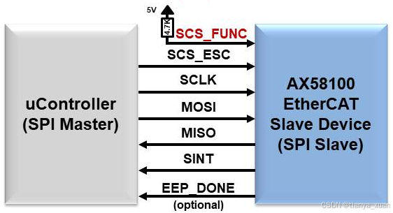
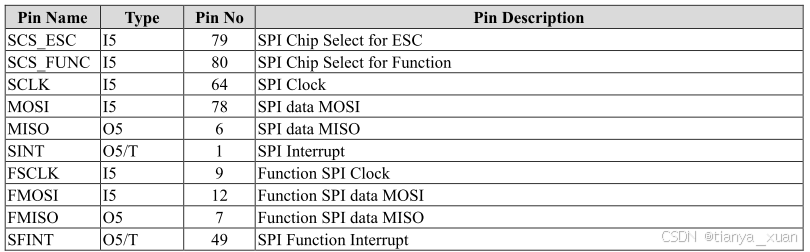
STM32与AX58100 SPI连接及定义
从站代码结构:
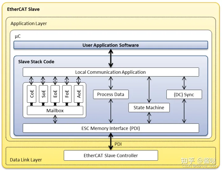
STM32与AX58100代码结构
2、软件接口
与AX58100通信,涉及到的外设包括以下几点:
1) PDI接口
SPI方式:4线标准SPI,AX58100支持SQI(6线高速SPI)。标准模式下,SPI时钟频率最高支持30M。AX58100还有高速SPI模式,时钟频率最高80M。
2) 1ms定时器
命名为ECAT_CheckTimer,协议栈的日常处理,包括看门狗喂狗行为,在定时器中断服务函数中进行,一般配置成1ms。
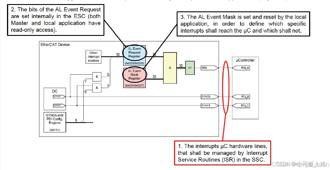
3) 3个外部中断
包括1个EtherCAT主中断,命名为PDI_Isr(ESC的SINT或LINT引脚);2个时钟同步IRQ,命名为Sync0_Isr(ESC的SYNC_LATCH[0]引脚),Sync1_Isr(ESC的SYNC_LATCH[1]引脚),EtherCAT主从通信中如果选择使用分布式时钟功能,这两个中断要配上。
NVIC方面,使用CubeMX配置时注意以下几点:
1)SPI无需配置中断,由ESC外部中断触发数据处理。
2) 3个外部中断,在CubeMX中都配置成初始enable,这样生成的代码友好一点,但到了Keil中,需要把初始化函数中最后一行Enable的语句给注释掉。什么时候Enable中断,什么时候Disable中断,都要由协议栈决定,而不是一上电就打开外部中断,那样非常容易出错,基本连不上。
3) 定时器中断,跟外部中断一样,CubeMX中配置好enable,代码生成后注释掉最后一行Enable,由协议栈来决定打开和关闭定时器中断。
注:实际使用中不注释掉2)和3)中提到的中断使能,也没遇到问题。
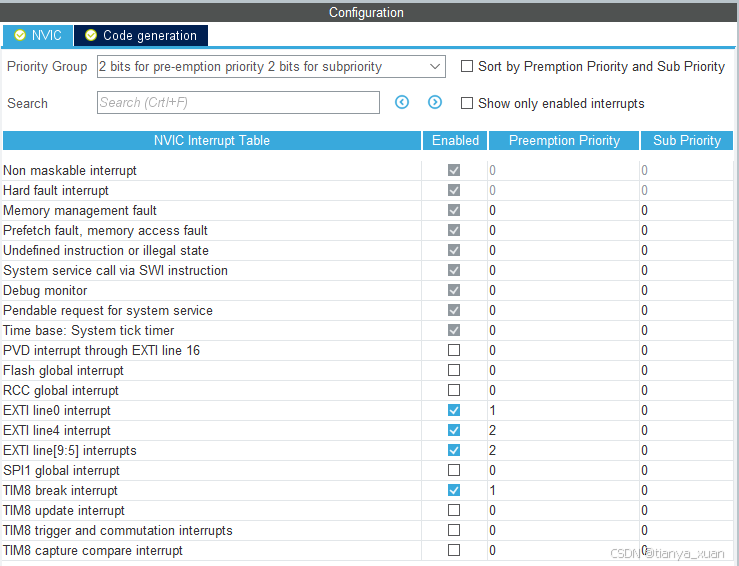
4) 中断向量,4bit抢先,0bit响应:
中断优先级建议:其他外设中断/定时器中断 > PDI_Isr > Sync0_Isr/Sync1_Isr
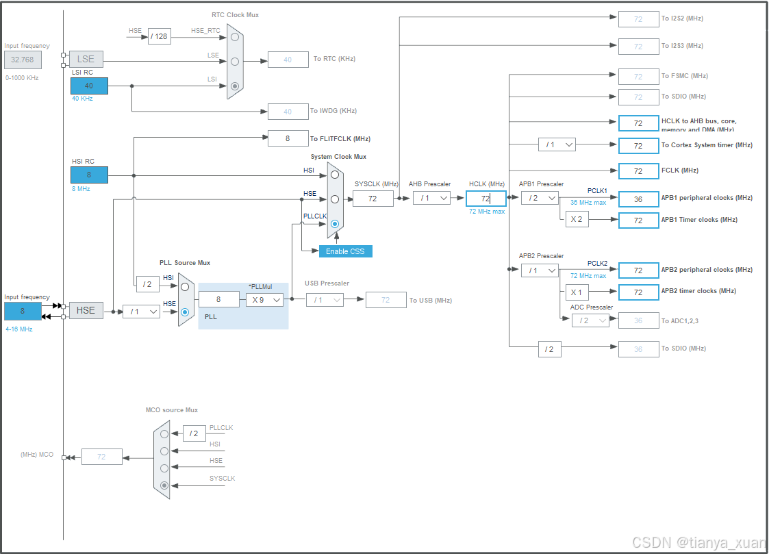
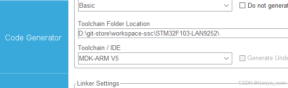
3、CubeMX配置
1)时钟:(根据所选的芯片型号配置)
2)SPI:(Mode: Full-Duplex Master)
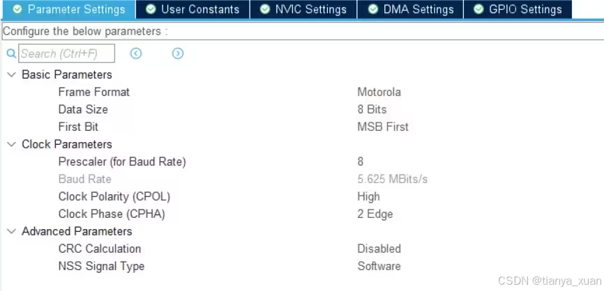
注:此处CPOL/CPHA设置对应EEPROM中的ConfigData中SPI mode3(03),如果设置为其他参数,则写入和读出的数据存在大小端不一致的问题。
3)Timer:1ms定时器
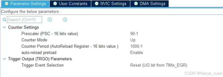
time = (Count + 1)*(Prescaler +1) / Tclk , 1000*72 / 72 us = 1ms
4)外部中断IO(以下截图为借用,可将名称改为PDI_Isr /Sync0_Isr/Sync1_Isr):
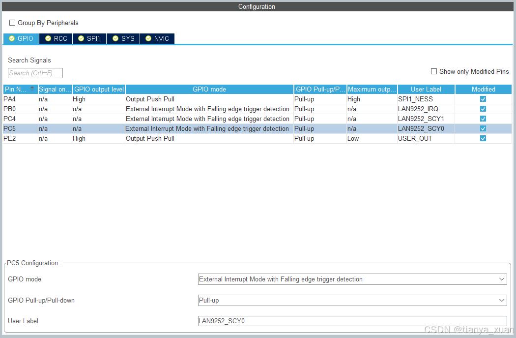
注:3个外部中断为下降沿触发。
5)NVIC:
6)KEIL5 工程模板:
7)模块化代码:
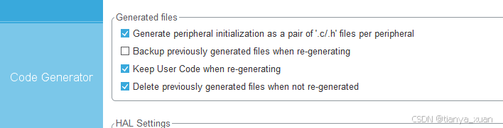
以上就是使用CubeMX配置的跟AX58100通信的所有外设资源。点击右上方的【GENERATE CODE】按钮,自动生成Keil5 工程代码。
4、从站代码移植
所谓的EtherCAT协议栈移植,其实就是将上面讲的各个外设资源的接口与EtherCAT协议栈的内部接口进行对接,比如SPI部分,我们需要封装一些简单的SPI操作,命名为协议栈期望的函数名,供协议栈调用;再比如3个外部中断和1个时间中断,我们需要在这4个中断服务函数中调用协议栈暴露给我们的4个不同的函数来适配协议栈。
将这些文件全都copy到STM32工程的一个目录中,比如新建一个EtherCAT目录。 在KEIL的工程结构中新建1个Group,比如命名为EtherCAT。
软件的适配主要包括以下几点:
- 协议栈移植,至少做到.c文件没有报错。
- SPI驱动移植
- 对接接口:将协议栈暴露给我们的几个函数,在代码相应的位置进行调用。
- 编写业务逻辑:根据在Excel中设计的IO交互数据,在指定的函数中编写业务逻辑。
4.1 对接接口
其中,这些函数均由协议栈提供:
el9800hw.c
HW_Init():硬件初始化函数,MCU通过此函数初始化AX58100设备。
ecatappl.c
PDI_Isr():EtherCAT主中断响应,需要配置到外部中断中,下降沿触发。
Sync0_Isr():分布式时钟同步信号0,需要配置到外部中断中,下降沿触发。
Sync1_Isr():分布式时钟同步信号1,需要配置到外部中断中,下降沿触发。
ECAT_CheckTimer():1ms定时器溢出中断,配置在STM32的TIMx的interrupt上。
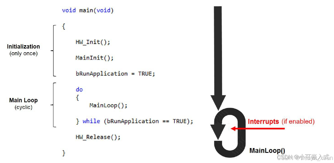
MainInit():协议栈初始化函数。
MainLoop():协议栈主循环,主while(1)中尽量只放此函数,其他业务逻辑在APPL_Application(void)函数中编写,后面介绍。
这些函数需要根据自己的业务逻辑编写:
myapp.c
APPL_InputMapping(UINT16 *pData) 输入数据映射
APPL_OutputMapping(UINT16 *pData) 输出数据映射
APPL_Application(void) 主业务逻辑
这些函数保持默认即可,也可添加自己的业务逻辑:
APPL_AckErrorInd(UINT16 stateTrans) EtherCAT通信故障时回调
APPL_StartMailboxHandler(void) 邮箱消息接收前回调
APPL_StopMailboxHandler(void) 邮箱消息接收后回调
APPL_StartInputHandler(UINT16 *pIntMask) 输入映射前回调
APPL_StopInputHandler(void) 输入映射后回调
APPL_StartOutputHandler(void)输出映射前回调
APPL_StopOutputHandler(void) 输出映射后回调
APPL_GenerateMapping()函数SSC生成代码时已经写好
4.2 主程序接口
4.2.1 HW_Init()
这个函数来自el9800hw.c, 在el9800hw.h中有其定义,主程序中直接#include el9800hw.h即可。
4.2.2 MainInit()
这个函数来自ecatappl.c, 在applInterface.h中有其定义,主程序中直接#include applInterface.h即可。
4.2.3 MainLoop()
同上。
/* Private includes ----------------------------------------------------------*/
/* USER CODE BEGIN Includes */
#include  "applInterface.h"
#include  "el9800hw.h"
/* USER CODE END Includes */

......
int main(void)
{
  /* USER CODE BEGIN 1 */

  /* USER CODE END 1 */

  /* MCU Configuration--------------------------------------------------------*/

  /* Reset of all peripherals, Initializes the Flash interface and the Systick. */
  HAL_Init();

  /* USER CODE BEGIN Init */
  HW_Init();
  MainInit();
  /* USER CODE END Init */

  /* Configure the system clock */
  SystemClock_Config();

  /* USER CODE BEGIN SysInit */

  /* USER CODE END SysInit */

  /* Initialize all configured peripherals */
  MX_GPIO_Init();
  MX_SPI3_Init();
  MX_USART3_UART_Init();
  MX_TIM2_Init();
  /* USER CODE BEGIN 2 */
  HAL_Delay(100);
  /* USER CODE END 2 */

  /* Infinite loop */
  /* USER CODE BEGIN WHILE */
  while (1)
  {
    MainLoop();
    /* USER CODE END WHILE */

    /* USER CODE BEGIN 3 */
  }
  /* USER CODE END 3 */
}
4.3 中断接口
4.3.1 PDI_Isr()
这个函数来自于ecatappl.c文件,头文件定义取自ecatappl.h,我们在主程序中直接#include applInterface.h即可。
4.3.2 Sync0_Isr() 和 Sync1_Isr()
这个函数来自于ecatappl.c文件,头文件定义取自ecatappl.h,我们在主程序中直接#include applInterface.h即可。
在主函数添加以下外部中断回调函数:
void HAL_GPIO_EXTI_Callback(uint16_t GPIO_Pin)
{
    /** handler PDI_IRQ interrupt */
    if (PDI_IRQ_Pin == GPIO_Pin)
    {
        /** from <ecatappl.c> */
        PDI_Isr();
    }
    /** handler SYNC0 interrupt */
    if (sync0_Pin == GPIO_Pin)
    {
        /** from <ecatappl.c> */
        Sync0_Isr();
    }
    /** handler SYNC1 interrupt */
    if (sync1_Pin == GPIO_Pin)
    {
        /** from <ecatappl.c> */
        Sync1_Isr();
    }
}
需要再次提醒的是,之前已经说过,CubeMX生成的中断初始化函数,在gpio.c中,有以下代码:
void MX_GPIO_Init(void)
{
  ……
   /* EXTI interrupt init*/
  HAL_NVIC_SetPriority(EXTI0_IRQn, 0, 0);
 //  HAL_NVIC_EnableIRQ(EXTI0_IRQn);

  HAL_NVIC_SetPriority(EXTI4_IRQn, 0, 0);
 //  HAL_NVIC_EnableIRQ(EXTI4_IRQn);

  HAL_NVIC_SetPriority(EXTI9_5_IRQn, 0, 0);
 // HAL_NVIC_EnableIRQ(EXTI9_5_IRQn);
}
设备上电后我们不可以直接调用HAL_NVIC_EnableIRQ函数将各种中断使能,因为此时协议栈相关数据都没初始化好,直接使能这些中断将导致严重的逻辑问题。因此上述代码后面的使能语句,都需要注释掉。
4.3.3 ECAT_CheckTimer()
这个函数来自于ecatappl.c文件,头文件定义取自ecatappl.h,我们在主程序中直接#include applInterface.h即可。 我们将其配置到TIMx的中断回调函数中去:
void HAL_TIM_PeriodElapsedCallback(TIM_HandleTypeDef *htim)
{
    // timer used esc timer 1ms
    if (htim->Instance == htim2.Instance)
    {
        DISABLE_ESC_INT();           //该函数不能被ESC中断函数打断
        /** from <ecatappl.c> */
        ECAT_CheckTimer();
        ENABLE_ESC_INT();
    }
}
4.4 硬件接口
SSC工具帮助生成了el9800hw.c硬件接口文档,但不适用于STM32和AX58100,,需要在此基础上进行修改:
#ifndef _EL9800HW_H_
#define _EL9800HW_H_


/*-----------------------------------------------------------------------------------------
------
------    Includes
------
-----------------------------------------------------------------------------------------*/
#include  "esc.h"


/*-----------------------------------------------------------------------------------------
------
------    Defines and Types
------
-----------------------------------------------------------------------------------------*/
#define ESC_RD                    0x02 /**< \brief Indicates a read access to ESC or EEPROM*/
#define ESC_WR                    0x04 /**< \brief Indicates a write access to ESC or EEPROM.*/


/*---------------------------------------------
-    Microcontroller definitions
-----------------------------------------------*/
#if    defined(_18F242) || defined(_18F252) || defined(_18F442) || defined(_18F452)
#define  ADREG                ADCON1
#define  ADREG_ALL_DIG_IO     0x07
#elif    defined(_18F2420) || defined(_18F2520) || defined(_18F4420) || defined(_18F4520)
#define  ADREG                ADCON1
#define  ADREG_ALL_DIG_IO     0x0F
#elif    defined(_18F23K20) || defined(_18F24K20) || defined(_18F25K20) || defined(_18F43K20) || defined(_18F44K20) || defined(_18F45K20)
#define  ADREG                ANSEL
#define  ADREG_ALL_DIG_IO     0x00
#endif


/*---------------------------------------------
-    hardware timer settings
-----------------------------------------------*/


/*---------------------------------------------
-    Interrupt and Timer defines
-----------------------------------------------*/


#define HW_EscReadByte(ByteValue, Address)      HW_EscRead(((MEM_ADDR *)&(ByteValue)),((UINT16)(Address)),1)  /**< \brief 8Bit ESC read access*/
#define HW_EscReadWord(WordValue, Address)      HW_EscRead(((MEM_ADDR *)&(WordValue)),((UINT16)(Address)),2)  /**< \brief 16Bit ESC read access*/
#define HW_EscReadDWord(DWordValue, Address)    HW_EscRead(((MEM_ADDR *)&(DWordValue)),((UINT16)(Address)),4) /**< \brief 32Bit ESC read access*/

#define HW_EscReadByteIsr(ByteValue, Address)   HW_EscReadIsr(((MEM_ADDR *)&(ByteValue)),((UINT16)(Address)),1)  /**< \brief Interrupt specific 8Bit ESC read access*/
#define HW_EscReadWordIsr(WordValue, Address)   HW_EscReadIsr(((MEM_ADDR *)&(WordValue)),((UINT16)(Address)),2)  /**< \brief Interrupt specific 16Bit ESC read access*/
#define HW_EscReadDWordIsr(DWordValue, Address) HW_EscReadIsr(((MEM_ADDR *)&(DWordValue)),((UINT16)(Address)),4) /**< \brief Interrupt specific 32Bit ESC read access*/

#define HW_EscWriteByte(ByteValue, Address)     HW_EscWrite(((MEM_ADDR *)&(ByteValue)),((UINT16)(Address)),1)  /**< \brief 8Bit ESC write access*/
#define HW_EscWriteWord(WordValue, Address)     HW_EscWrite(((MEM_ADDR *)&(WordValue)),((UINT16)(Address)),2)  /**< \brief 16Bit ESC write access*/
#define HW_EscWriteDWord(DWordValue, Address)   HW_EscWrite(((MEM_ADDR *)&(DWordValue)),((UINT16)(Address)),4) /**< \brief 32Bit ESC write access*/

#define HW_EscWriteByteIsr(ByteValue, Address)  HW_EscWriteIsr(((MEM_ADDR *)&(ByteValue)),((UINT16)(Address)),1) /**< \brief Interrupt specific 8Bit ESC write access*/
#define HW_EscWriteWordIsr(WordValue, Address)  HW_EscWriteIsr(((MEM_ADDR *)&(WordValue)),((UINT16)(Address)),2) /**< \brief Interrupt specific 16Bit ESC write access*/
#define HW_EscWriteDWordIsr(DWordValue, Address)HW_EscWriteIsr(((MEM_ADDR *)&(DWordValue)),((UINT16)(Address)),4)/**< \brief Interrupt specific 32Bit ESC write access*/

#define HW_EscReadMbxMem(pData,Address,Len)     HW_EscRead(((MEM_ADDR *)(pData)),((UINT16)(Address)),(Len))  /**< \brief The mailbox data is stored in the local uC memory therefore the default read function is used.*/
#define HW_EscWriteMbxMem(pData,Address,Len)    HW_EscWrite(((MEM_ADDR *)(pData)),((UINT16)(Address)),(Len)) /**< \brief The mailbox data is stored in the local uC memory therefore the default write function is used.*/

#endif //_EL9800HW_H_

/* ECATCHANGE_START(V5.11) ECAT10*/
#if defined(_EL9800HW_) && (_EL9800HW_ == 1)
/* ECATCHANGE_END(V5.11) ECAT10*/
    #define PROTO
#else
    #define PROTO extern
#endif


/*-----------------------------------------------------------------------------------------
------
------    Global variables
------
-----------------------------------------------------------------------------------------*/


/*-----------------------------------------------------------------------------------------
------
------    Global functions
------
-----------------------------------------------------------------------------------------*/
PROTO UINT8 HW_Init(void);
PROTO void  HW_Release(void);

PROTO UINT16 HW_GetALEventRegister(void);
PROTO UINT16 HW_GetALEventRegister_Isr(void);


PROTO void HW_EscRead( MEM_ADDR * pData, UINT16 Address, UINT16 Len );
PROTO void HW_EscReadIsr( MEM_ADDR *pData, UINT16 Address, UINT16 Len );

PROTO void HW_EscWrite( MEM_ADDR *pData, UINT16 Address, UINT16 Len );
PROTO void HW_EscWriteIsr( MEM_ADDR *pData, UINT16 Address, UINT16 Len );

#undef    PROTO
/** @}*/
el9800hw.c
/**
\file    el9800hw.c
\author EthercatSSC@beckhoff.com
\brief Implementation
Hardware access implementation for EL9800 onboard PIC18/PIC24 connected via SPI to ESC

\version 5.11

*/


/*--------------------------------------------------------------------------------------
------
------    Includes
------
--------------------------------------------------------------------------------------*/
#include "ecat_def.h"

#include "ecatslv.h"

#define    _EL9800HW_ 1
#include "el9800hw.h"
#undef    _EL9800HW_
/* ECATCHANGE_START(V5.11) ECAT10*/
/*remove definition of _EL9800HW_ (#ifdef is used in el9800hw.h)*/
/* ECATCHANGE_END(V5.11) ECAT10*/

#include "ecatappl.h"

#include  "gpio.h"
#include  "spi.h"

/*--------------------------------------------------------------------------------------
------
------    internal Types and Defines
------
--------------------------------------------------------------------------------------*/

typedef union
{
    unsigned short    Word;
    unsigned char    Byte[2];
} UBYTETOWORD;

typedef union
{
    UINT8           Byte[2];
    UINT16          Word;
}
UALEVENT;

/*-----------------------------------------------------------------------------------------
------
------    SPI defines/macros
------
-----------------------------------------------------------------------------------------*/
#difine SELECT_SPI       HAL_GPIO_WritePin(SPI3_NSS_GPIO_Port, SPI3_NSS_Pin, GPIO_PIN_RESET)
#difine DESELECT_SPI     HAL_GPIO_WritePin(SPI3_NSS_GPIO_Port, SPI3_NSS_Pin, GPIO_PIN_SET)
/*-----------------------------------------------------------------------------------------
------
------    Global Interrupt setting
------
-----------------------------------------------------------------------------------------*/
#define     ENABLE_GLOBAL_INT()       __enable_irq()
#define     DISABLE_GLOBAL_INT()      __disable_irq()
#define     ENABLE_AL_EVENT_INT       ENABLE_GLOBAL_INT()
#define     DISABLE_AL_EVENT_INT      DISABLE_GLOBAL_INT()
/*-----------------------------------------------------------------------------------------
------
------    ESC Interrupt
------
-----------------------------------------------------------------------------------------*/
//PDI_Isr
#define ENABLE_ESC_INT()    HAL_NVIC_EnableIRQ(EXTI0_IRQn)
#define DISABLE_ESC_INT()   HAL_NVIC_DienableIRQ(EXTI0_IRQn)
//Sync0_Isr
#define ENABLE_SYNCO_INT()    HAL_NVIC_EnableIRQ(EXTI9_5_IRQn)
#define DISABLE_SYNCO_INT()   HAL_NVIC_DienableIRQ(EXTI9_5_IRQn)
//Sync1_Isr
#define ENABLE_SYNC1_INT()    HAL_NVIC_EnableIRQ(EXTI4_IRQn)
#define DISABLE_SYNC1_INT()   HAL_NVIC_DienableIRQ(EXTI4_IRQn)
/*-----------------------------------------------------------------------------------------
------
------    Hardware timer
------
-----------------------------------------------------------------------------------------*/
#define START_ECAT_TIMER()    HAL_TIM_Base_Start_IT(&htim3)
#define STOP_ECAT_TIMER()     HAL_TIM_Base_Stop_IT(&htim3)

#define HW_GetTimer()         __HAL_TIM_GET_COUNTER(&htim3)
#define ECAT_TIMER_INC_P_MS   1000  //1ms定时器的计数值
/*-----------------------------------------------------------------------------------------
------
------    Configuration Bits
------
-----------------------------------------------------------------------------------------*/

/*-----------------------------------------------------------------------------------------
------
------    LED defines
------
-----------------------------------------------------------------------------------------*/

/*--------------------------------------------------------------------------------------
------
------    internal Variables
------
--------------------------------------------------------------------------------------*/
UALEVENT         EscALEvent;            //contains the content of the ALEvent register (0x220), this variable is updated on each Access to the Esc

/*--------------------------------------------------------------------------------------
------
------    internal functions
------
--------------------------------------------------------------------------------------*/
/
/**
 \brief  spi send and receive.
*
uint8_t WR_CMD (uint8_t cmd)
{
    uint8_t tmp;
    HAL_SPI_TransmitReceive(&hspi3, &cmd, &temp, 1, 100);

    return temp;
}

/
/**
 \brief  The function operates a SPI access without addressing.

        The first two bytes of an access to the EtherCAT ASIC always deliver the AL_Event register (0x220).
        It will be saved in the global "EscALEvent"
*
static void GetInterruptRegister(void)
{
    DISABLE_AL_EVENT_INT;

    /* select the SPI */
    SELECT_SPI;

    HW_EscReadWord(EscALEvent.word, ESC_AL_EVENT_OFFSET);

    /* if the SPI transmission rate is higher than 15 MBaud, the Busy detection shall be
       done here */

    DESELECT_SPI;

    ENABLE_AL_EVENT_INT;
}

/
/**
 \brief  The function operates a SPI access without addressing.
        Shall be implemented if interrupts are supported else this function is equal to "GetInterruptRegsiter()"

        The first two bytes of an access to the EtherCAT ASIC always deliver the AL_Event register (0x220).
        It will be saved in the global "EscALEvent"
*
static void ISR_GetInterruptRegister(void)
{
    /* SPI should be deactivated to interrupt a possible transmission */
    DESELECT_SPI;

    /* select the SPI */
    SELECT_SPI;

    HW_EscReadWordIsr(EscALEvent.word, ESC_AL_EVENT_OFFSET);

    /* if the SPI transmission rate is higher than 15 MBaud, the Busy detection shall be
       done here */

    DESELECT_SPI;
}


/
/**
 \param Address     EtherCAT ASIC address ( upper limit is 0x1FFF )    for access.
 \param Command    ESC_WR performs a write access; ESC_RD performs a read access.

 \brief The function addresses the EtherCAT ASIC via SPI for a following SPI access.
*
static void AddressingEsc( UINT16 Address, UINT8 Command )
{
    UBYTETOWORD tmp;
    VARVOLATILE UINT8 dummy;
    tmp.Word = ( Address << 3 ) | Command;
    /* select the SPI */
    SELECT_SPI;


    /* there have to be at least 15 ns after the SPI1_SEL signal was active (0) before
       the transmission shall be started */
    /* send the first address/command byte to the ESC */

    dummy =  WR_CMD(tmp.Byte[1]);

    /* send the second address/command byte to the ESC */

    dummy = WR_CMD(tmp.Byte[0]);

    /* if the SPI transmission rate is higher than 15 MBaud, the Busy detection shall be
       done here */
}

/
/**
 \param Address     EtherCAT ASIC address ( upper limit is 0x1FFF )    for access.
 \param Command    ESC_WR performs a write access; ESC_RD performs a read access.

 \brief The function addresses the EtherCAT ASIC via SPI for a following SPI access.
        Shall be implemented if interrupts are supported else this function is equal to "AddressingEsc()"
*
static void ISR_AddressingEsc( UINT16 Address, UINT8 Command )
{
    VARVOLATILE UINT8 dummy;
    UBYTETOWORD tmp;
    tmp.Word = ( Address << 3 ) | Command;

    /* select the SPI */
    SELECT_SPI;

    /* there have to be at least 15 ns after the SPI1_SEL signal was active (0) before
      the transmission shall be started */

    /* send the first address/command byte to the ESC */
    dummy = WR_CMD(tmp.Byte[1]);

    /* send the second address/command byte to the ESC */

    dummy = WR_CMD(tmp.Byte[0]);
    /* if the SPI transmission rate is higher than 15 MBaud, the Busy detection shall be
       done here */
}

/*--------------------------------------------------------------------------------------
------
------    exported hardware access functions
------
--------------------------------------------------------------------------------------*/


/
/**
\return     0 if initialization was successful

\brief    This function intialize the Process Data Interface (PDI) and the host controller.
*
UINT8 HW_Init(void)
{
/*ECATCHANGE_START(V5.11) EL9800 2*/
    UINT32 intMask;
/*ECATCHANGE_END(V5.11) EL9800 2*/

//    PORT_CFG;


    /* initialize the SPI registers for the ESC SPI */
//    SPI1_CON1 = SPI1_CON1_VALUE;
//    SPI1_STAT = SPI1_STAT_VALUE;
    /* make sure it's spi */
    do
    {
        intMask = 0x00;
        HW_EscReadByte(intMask, ESC_PDI_CONTROL_OFFSET);
    } while (intMask != 0x05);
/*ECATCHANGE_START(V5.11) EL9800 2*/
    do
    {
        intMask = 0x93;
        HW_EscWriteDWord(intMask, ESC_AL_EVENTMASK_OFFSET);
        intMask = 0;
        HW_EscReadDWord(intMask, ESC_AL_EVENTMASK_OFFSET);

    } while (intMask != 0x93);

    intMask = 0x00;

    HW_EscWriteDWord(intMask, ESC_AL_EVENTMASK_OFFSET);

/*ECATCHANGE_END(V5.11) EL9800 2*/
#if AL_EVENT_ENABLED
   ENABLE_ESC_INT();
#endif

#if DC_SUPPORTED
   ENABLE_SYNC0_INT();
   ENABLE_SYNC1_INT();
#endif

#if ECAT_TIMER_INT
    START_ECAT_TIMER();
#endif

#if INTERRUPTS_SUPPORTED
    /* enable all interrupts */
    ENABLE_GLOBAL_INT();
#endif

    return 0;
}


/
/**
 \brief    This function shall be implemented if hardware resources need to be release
        when the sample application stops
*
void HW_Release(void)
{
    DISABLE_GLOBAL_INT();
}

/
/**
 \return    first two Bytes of ALEvent register (0x220)

 \brief  This function gets the current content of ALEvent register
*
UINT16 HW_GetALEventRegister(void)
{
    GetInterruptRegister();
    return EscALEvent.Word;
}

/
/**
 \return    first two Bytes of ALEvent register (0x220)

 \brief  The SPI PDI requires an extra ESC read access functions from interrupts service routines.
        The behaviour is equal to "HW_GetALEventRegister()"
*
UINT16 HW_GetALEventRegister_Isr(void)
{
    ISR_GetInterruptRegister();
    return EscALEvent.Word;
}


/
/**
 \param pData        Pointer to a byte array which holds data to write or saves read data.
 \param Address     EtherCAT ASIC address ( upper limit is 0x1FFF )    for access.
 \param Len            Access size in Bytes.

 \brief  This function operates the SPI read access to the EtherCAT ASIC.
*
void HW_EscRead( MEM_ADDR *pData, UINT16 Address, UINT16 Len )
{
    /* HBu 24.01.06: if the SPI will be read by an interrupt routine too the
                     mailbox reading may be interrupted but an interrupted
                     reading will remain in a SPI transmission fault that will
                     reset the internal Sync Manager status. Therefore the reading
                     will be divided in 1-byte reads with disabled interrupt */
    UINT16 i = Len;
    UINT8 *pTmpData = (UINT8 *)pData;

    /* loop for all bytes to be read */
    while ( i-- > 0 )
    {
#if AL_EVENT_ENABLED
        /* the reading of data from the ESC can be interrupted by the
           AL Event ISR, in that case the address has to be reinitialized,
           in that case the status flag will indicate an error because
           the reading operation was interrupted without setting the last
           sent byte to 0xFF */
        DISABLE_AL_EVENT_INT;
#endif
        AddressingEsc( Address, ESC_RD );

        /* when reading the last byte the DI pin shall be 1 */
        *pTmpData++ = WR_CMD(0xFF);
        /* enable the ESC interrupt to get the AL Event ISR the chance to interrupt,
           if the next byte is the last the transmission shall not be interrupted,
           otherwise a sync manager could unlock the buffer, because the last was
           read internally */
#if AL_EVENT_ENABLED
        ENABLE_AL_EVENT_INT;
#endif
        /* there has to be at least 15 ns + CLK/2 after the transmission is finished
           before the SPI1_SEL signal shall be 1 */
        DESELECT_SPI;
        /* next address */
        Address++;
//        /* reset transmission flag */
//        SPI1_IF = 0;
    }
}

/
/**
 \param pData        Pointer to a byte array which holds data to write or saves read data.
 \param Address     EtherCAT ASIC address ( upper limit is 0x1FFF )    for access.
 \param Len            Access size in Bytes.

\brief  The SPI PDI requires an extra ESC read access functions from interrupts service routines.
        The behaviour is equal to "HW_EscRead()"
*
void HW_EscReadIsr( MEM_ADDR *pData, UINT16 Address, UINT16 Len )
{
    UINT16 i = Len;
    UINT8 data = 0;

    UINT8 *pTmpData = (UINT8 *)pData;

    /* send the address and command to the ESC */
    ISR_AddressingEsc( Address, ESC_RD );
    /* loop for all bytes to be read */
    while ( i-- > 0 )
    {
        if ( i == 0 )
        {
            /* when reading the last byte the DI pin shall be 1 */
            data = 0xFF;
        }

        *pTmpData++ = WR_CMD(data);
    }

    /* there has to be at least 15 ns + CLK/2 after the transmission is finished
       before the SPI1_SEL signal shall be 1 */
    DESELECT_SPI;
}

/
/**
 \param pData        Pointer to a byte array which holds data to write or saves write data.
 \param Address     EtherCAT ASIC address ( upper limit is 0x1FFF )    for access.
 \param Len            Access size in Bytes.

  \brief  This function operates the SPI write access to the EtherCAT ASIC.
*
void HW_EscWrite( MEM_ADDR *pData, UINT16 Address, UINT16 Len )
{
    UINT16 i = Len;
    VARVOLATILE UINT8 dummy;

    UINT8 *pTmpData = (UINT8 *)pData;

    /* loop for all bytes to be written */
    while ( i-- > 0 )
    {
#if AL_EVENT_ENABLED
        /* the reading of data from the ESC can be interrupted by the
           AL Event ISR, so every byte will be written separate */
        DISABLE_AL_EVENT_INT;
#endif
        /* HBu 24.01.06: wrong parameter ESC_RD */
        AddressingEsc( Address, ESC_WR );

        /* enable the ESC interrupt to get the AL Event ISR the chance to interrupt */
        /* SPI1_BUF must be read, otherwise the module will not transfer the next received data from SPIxSR to SPIxRXB.*/
        dummy= WR_CMD(*pTmpData++);

#if AL_EVENT_ENABLED
        ENABLE_AL_EVENT_INT;
#endif

        DESELECT_SPI;
        /* next address */
        Address++;
    }
}

/
/**
 \param pData        Pointer to a byte array which holds data to write or saves write data.
 \param Address     EtherCAT ASIC address ( upper limit is 0x1FFF )    for access.
 \param Len            Access size in Bytes.

 \brief  The SPI PDI requires an extra ESC write access functions from interrupts service routines.
        The behaviour is equal to "HW_EscWrite()"
*
void HW_EscWriteIsr( MEM_ADDR *pData, UINT16 Address, UINT16 Len )
{
    UINT16 i = Len;
    VARVOLATILE UINT16 dummy;
    UINT8 *pTmpData = (UINT8 *)pData;

    /* send the address and command to the ESC */
     ISR_AddressingEsc( Address, ESC_WR );
    /* loop for all bytes to be written */
    while ( i-- > 0 )
    {
        /* start transmission */
        dummy= WR_CMD(*pTmpData);
        /* increment data pointer */
        pTmpData++;
    }

    /* there has to be at least 15 ns + CLK/2 after the transmission is finished
       before the SPI1_SEL signal shall be 1 */
    DESELECT_SPI;
}


/** @} */
4.5 业务逻辑接口
上面提到很多回调函数(myapp.h/c),在EtherCAT协议栈中,使用了extern关键字来调用那些函数,因此我们需要有这些函数的实体。
4.5.1 APPL_GenerateMapping()
这个函数是根据我们定义的过程通信数据,与内存中的数据进行映射的函数,这个函数由SSC自动生成,不需要修改。
4.5.2 APPL_InputMapping(UINT16 *pData)
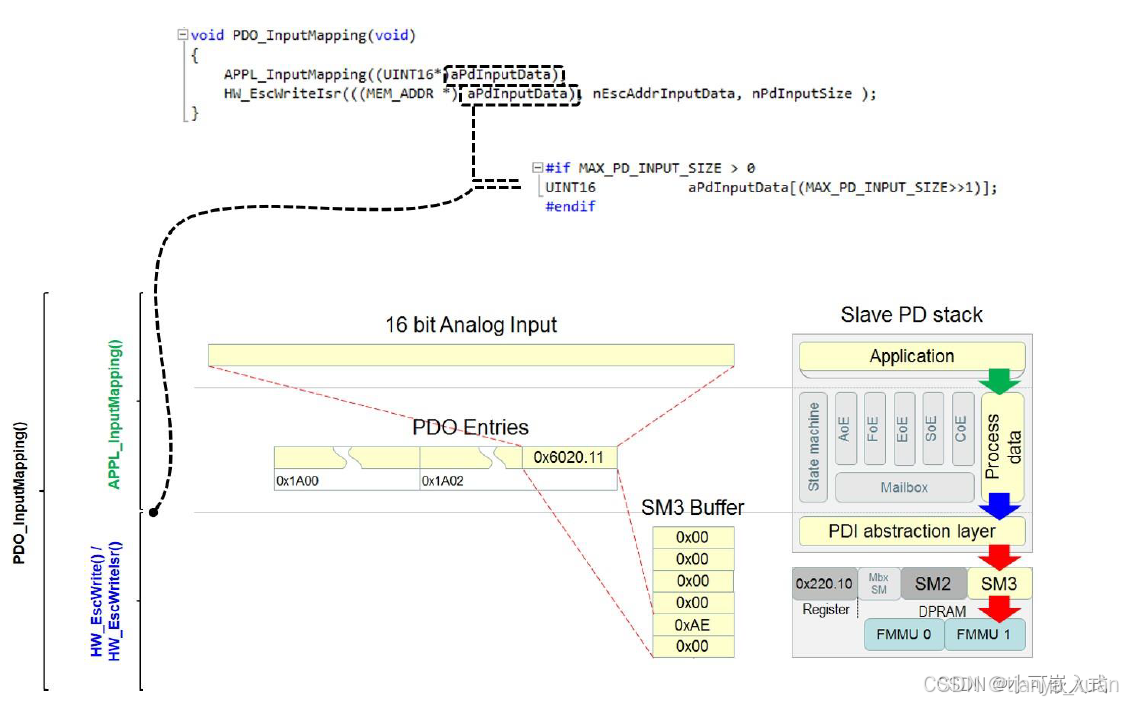
这个函数是输入数据映射函数,实现将从站数据输出的功能。这里的【输入】是相对于主站来说,也就是从站的输出数据。
void APPL_InputMapping(UINT16* pData)
{
  *pData = Results0x6000.Result1;
  pData++;
  *pData = Results0x6000.Result2;
  pData++;
  *pData = Results0x6000.Toggle;
}
注:
也可以使用memcpy函数更为简洁,但要注意拷贝的数据从Results0x6000第二个成员地址开始。
memcpy(pData,&Results0x6000.Result1,sizeof(Results0x6000)-2);
pData += (sizeof(Results0x6000)-2)/2;
如成员类型不一致,则Results0x6000的地址可能不连续,按地址拷贝很可能出错,这种情况下要用成员直接赋值。
4.5.3 APPL_OutputMapping(UINT16 *pData)
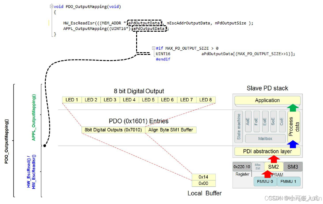
同理,该函数这么编写:
void APPL_OutputMapping(UINT16* pData)
{
  SetpointValues0x7000.Value1 = *pData;
  pData++;
  SetpointValues0x7000.Value2 = *pData;
}
注:
也可以使用memcpy函数更为简洁,但要注意拷贝的数据从SetpointValues0x7000第二个成员地址开始。
memcpy(&SetpointValues0x7000.Value1,pData,sizeof(SetpointValues0x7000)-2);
pData += (sizeof(SetpointValues0x7000)-2)/2;
如成员类型不一致,则SetpointValues0x7000的地址可能不连续,按地址拷贝很可能出错,这种情况下要对成员直接赋值。
4.5.4 APPL_Application(void)
该函数为用户应用程序,对输入输出数据进行逻辑处理,以下为参考。
void APPL_Application(void)
{
  Results0x6000.Result1 += Parameters0x8000.Inc1;
  Results0x6000.Result2 = SetpointValues0x7000.Value1+SetpointValues0x7000.Value2;
}
4.5.5 APPL_StopOutputHandler(void)
该函数处理主站退出时的逻辑,比如关闭点亮的灯等。
UINT16 APPL_StopOutputHandler(void)
{
    ......

    return ALSTATUSCODE_NOERROR;
}
至此STM32与AX58100对接的所有接口都完成了,编译无误的话可以试着下载到设备中去。观察看看AX58100的RUN灯是否可以常亮。


 1238
1238

 被折叠的 条评论
为什么被折叠?
被折叠的 条评论
为什么被折叠?
 到【灌水乐园】发言


