


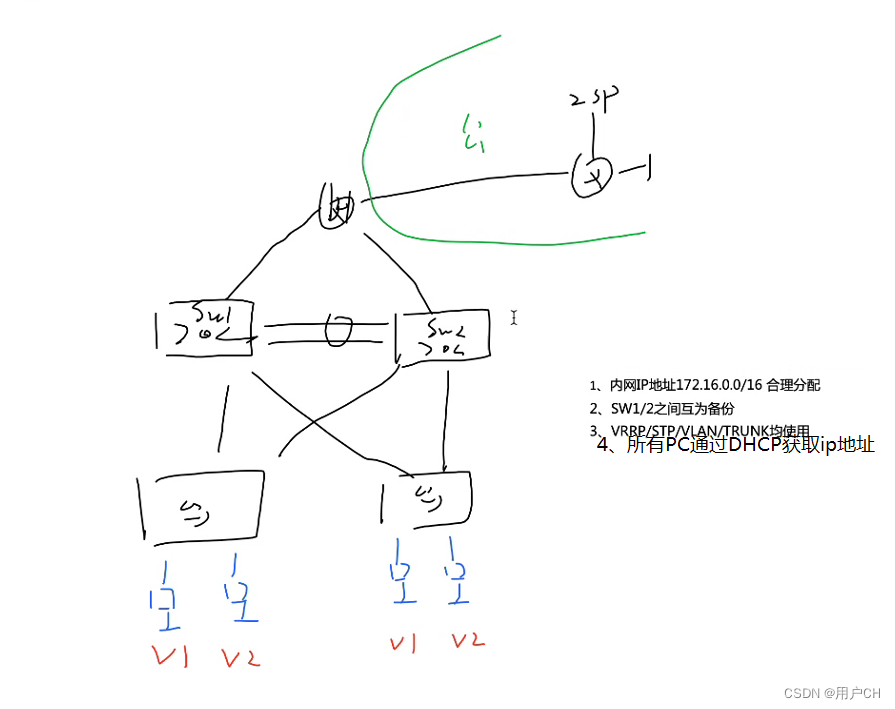
实验需求:
1.内网IP地址172.16.0.0/16 合理分配
2.SW1/2之间互为备份
3.VRRP/STP/VLAN/TRUNK均使用
4.所有PC通过DHCP获取IP地址
5.内网可以访问外网
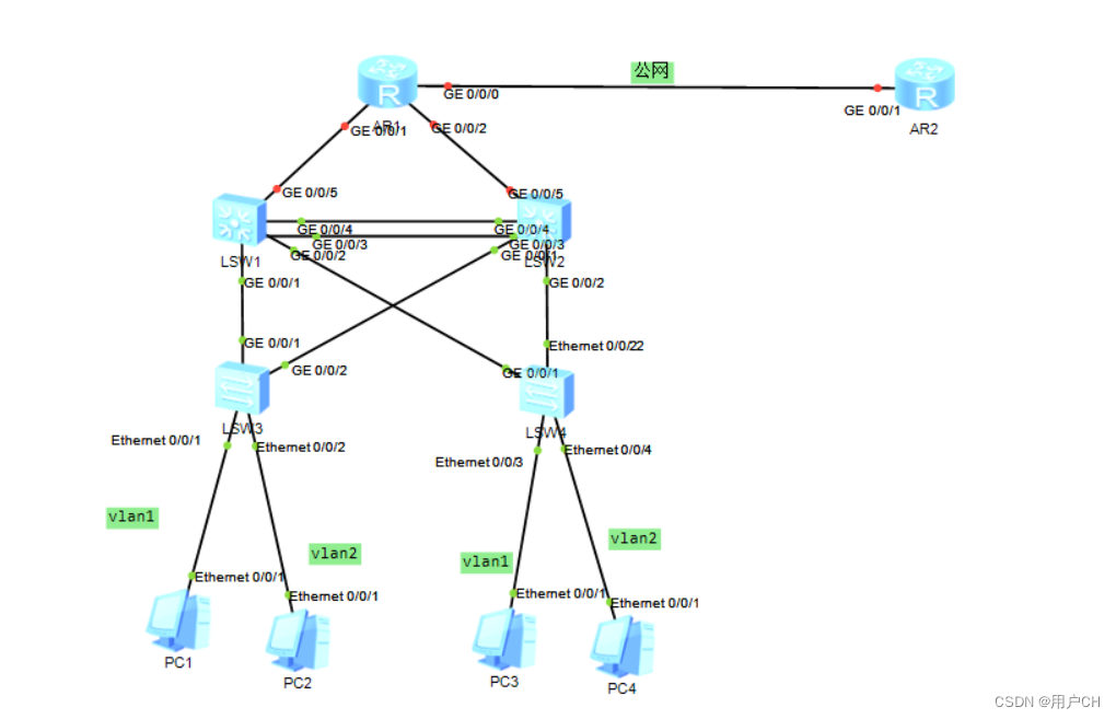
实验步骤:
1.拓扑搭建
2.创建Trunk通道
sw1
[sw1]interface Eth-Trunk 0
[sw1-Eth-Trunk0]q
[sw1]interface GigabitEthernet 0/0/3
[sw1-GigabitEthernet0/0/3]eth-trunk 0
[sw1-GigabitEthernet0/0/3]int g0/0/4
[sw1-GigabitEthernet0/0/4]eth-trunk 0


SW2
[sw2]interface Eth-Trunk 0
[sw2-Eth-Trunk0]q
[sw2]interface GigabitEthernet 0/0/3
[sw2-GigabitEthernet0/0/3]eth-trunk 0
[sw2-GigabitEthernet0/0/3]int g0/0/4
[sw2-GigabitEthernet0/0/4]eth-trunk 0
3.创建并划分VLAN
[SW1]vlan 2
[SW1]port-group group-member g0/0/1 g0/0/2 Eth-Trunk 0
[SW1-port-group]p l t
[SW1-port-group]port trunk allow-pass vlan 2

[SW3]port-group group-member g0/0/1 g0/0/2
[SW3-port-group]p l t
[SW3-port-group]port trunk allow-pass vlan 2
[SW3]int e0/0/2
[SW3-Ethernet0/0/2] port link-type access
[SW3-Ethernet0/0/2] port default vlan 2
4.同MSTP把多个vlan划为同一组,每个组一棵生成树
[SW1]stp mode mstp
[sw1]stp enable
[sw1]stp region-configuration
[sw1-mst-region]region-name a
[sw1-mst-region]instance 1 vlan 1
[sw1-mst-region]instance 2 vlan 2
[sw1-mst-region]active region-configuration
[SW1]stp instance 1 root primary
[SW1]stp instance 2 root secondary

[SW2]stp instance 2 root primary
[SW2]stp instance 1 root secondary
5.创建SVI和VRRP定义上行链路追踪启用边缘端口功能
[SW1]int vlan 1
[SW1-Vlanif1] ip address 172.16.1.1 255.255.255.128
[SW1-Vlanif1] vrrp vrid 1 virtual-ip 172.16.1.126
[SW1-Vlanif1] vrrp vrid 1 priority 110
[SW1-Vlanif1] vrrp vrid 1 track interface GigabitEthernet0/0/5 reduced 15
[SW1]int vlan 2
[SW1-Vlanif2] ip address 172.16.1.129 255.255.255.128
[SW1-Vlanif2] vrrp vrid 1 virtual-ip 172.16.1.254


[SW2]int vlan 1
[SW2-Vlanif1] ip address 172.16.1.2 255.255.255.128
[SW2-Vlanif1] vrrp vrid 1 virtual-ip 172.16.1.126

[SW2]int vlan 2
[SW2-Vlanif2] ip address 172.16.1.130 255.255.255.128
[SW2-Vlanif2] vrrp vrid 1 virtual-ip 172.16.1.254
[SW2-Vlanif2] vrrp vrid 1 priority 110
[SW2-Vlanif2] vrrp vrid 1 track interface GigabitEthernet0/0/5 reduced 15


[SW3]int e0/0/2
[SW3-Ethernet0/0/2] stp edged-port enable
6.配置DHCP地址池
[SW1]ip pool v1
[SW1-ip-pool-v1] gateway-list 172.16.1.126
[SW1-ip-pool-v1] network 172.16.1.0 mask 255.255.255.128
[SW1-Vlanif1] dhcp select global

[SW1]ip pool v2
[SW1-ip-pool-v2] gateway-list 172.16.1.254
[SW1-ip-pool-v2] network 172.16.1.128 mask 255.255.255.128
[SW1-Vlanif2] dhcp select global
7.配置缺省和nat,保证全网可达
[SW1] vlan 100
[SW1]int vlan 100
[SW1-Vlanif100] ip address 172.16.0.2 255.255.255.252
[SW1]int g0/0/5
[SW1-GigabitEthernet0/0/5] port link-type access
[SW1-GigabitEthernet0/0/5] port default vlan 100
[SW1] ip route-static 0.0.0.0 0.0.0.0 172.16.0.1

[SW2]ip route-static 0.0.0.0 0.0.0.0 172.16.0.5

[R1] ip route-static 0.0.0.0 0.0.0.0 12.1.1.2
[R1] ip route-static 172.16.1.0 255.255.255.0 172.16.0.2
[R1] ip route-static 172.16.1.0 255.255.255.0 172.16.0.6
[R1]acl 2000
[R1-acl-basic-2000] rule 5 permit source 172.16.0.0 0.0.255.255
[R1]int g0/0/0
[R1-GigabitEthernet0/0/0] nat outbound 2000
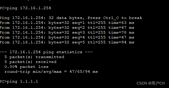
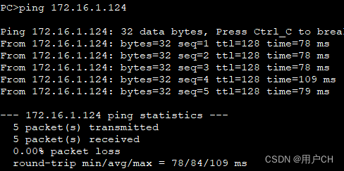
8.实验验证


 1万+
1万+

 被折叠的 条评论
为什么被折叠?
被折叠的 条评论
为什么被折叠?
 到【灌水乐园】发言


