


概要:
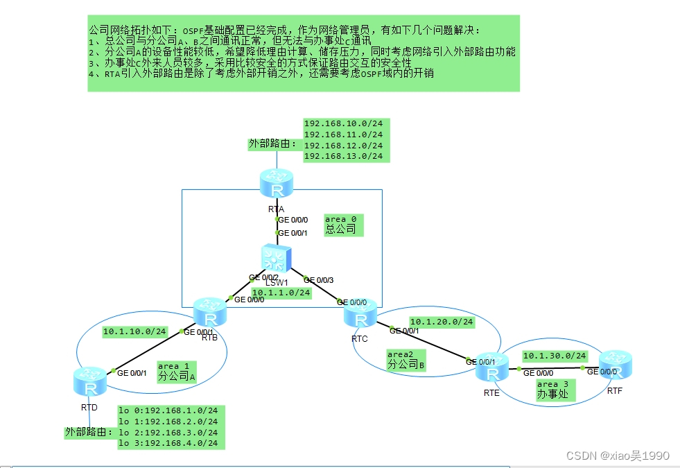
公司网络拓扑如下:OSPF基础配置已经完成,作为网络管理员,有如下几个问题解决:
1、总公司与分公司A、B之间通讯正常,但无法与办事处C通讯
2、分公司A的设备性能较低,希望降低理由计算、储存压力,同时考虑网络引入外部路由功能
3、办事处C外来人员较多,采用比较安全的方式保证路由交互的安全性
4、RTA引入外部路由是除了考虑外部开销之外,还需要考虑OSPF域内的开销
拓扑图:
技术名词解释:
display ospf lsdb #查询ospf数据ku
display ospf peer brief #查询ospf邻居
display ip route-table protocol ospf #查询ospf路由
display ospf vlink #查询ospf虚链路
路由器LSA1(RouterLSA):区域内的每一台路由器都会通告。描述路由器的直连链路状态信息。只在本区域内传递,不会超过ABR。
网络LSA2(NetworkLSA):由一个多路访问网络中的DR产生网络LSA通告。描述与之相连的路由器包括DR路由器本身
网络汇总LSA3(Networksummary LSA):是由ABR路由器始发,描述区域间路由,用来通告区域外部的目的地址。
ASBR汇总LSA4(ASBRsummary LSA):是由ABR路由器始发出的。通告的内容是一个ASBR路由器。为LSA5服务的
自治系统外部LSA 5(Autonomoussystem external LSA):或称为外部LSA(ExternalLSA),始发于ASBR路由器,用来通告到达OSPF自主系统外部的目的地或者OSPF自主系统外部的缺省路由的LSA。在整个自主系统中进行泛洪。
NSSA外部LSA7(NSSAExternal LSA):指在非纯末梢区域内始发于ASBR路由器(在非纯末梢区域内部)的LSA通告,只在始发这个LSA的非纯末梢区域内泛洪。非纯末梢区域内的ABR可以讲这类LSA转换为LSA5,然后再骨干区域内泛洪。
技术细节:
1、为了使总部RTA与办事处RTF通讯,需要在RTC与RTD间配置虚链路
2、分公司A性能设备较低,为降低路由计算、储存压力,可以在ASBR、ABR配置路由汇聚,在RTB与RTD配置NSSA区域屏蔽LSA4、LSA5,但区域可以允许有ASBR
3、为解决办事处外来人员较多,保证路由交换安全,可以配置区域间或者端口间的OSPF认证
4、为保证RTA引入外部路由能在内部计算开销,可配置路由策略并在引入策略时将type改为1(默认为2)
配置如下:
基础配置:
RTA:
sy
sys RTA
int g0/0/0
ip add 10.1.1.1 24
int lo 0
ip add 192.168.10.1 24  #配置外部路由(将回环口默认为外部路由)
int lo 1
ip add 192.168.11.1 24
int lo 2
ip add 192.168.12.1 24
int lo 3
ip add 192.168.13.1 24

ospf router-id 1.1.1.1
a 0
net 10.1.1.1 0.0.0.0  #宣告路由

RTB:
sy
sys RTB
int g0/0/0
ip add 10.1.1.2 24
int g0/0/1
ip add 10.1.10.1 24

ospf router-id 2.2.2.2
a 0
net 10.1.1.2 0.0.0.0
a 1
net 10.1.10.1 0.0.0.0

RTC:
sy
sys RTC
int g0/0/0
ip add 10.1.1.3 24
int g0/0/1
ip add 10.1.20.1 24

ospf router-id 3.3.3.3
a 0
net 10.1.1.3 0.0.0.0
a 2
net 10.1.20.1 0.0.0.0

RTD:
sy
sys RTD
int g0/0/1
ip add 10.1.10.2 24
int lo 0
ip add 192.168.1.1 24
int lo 1
ip add 192.168.2.1 24
int lo 2
ip add 192.168.3.1 24
int lo 3
ip add 192.168.4.1 24

ospf router-id 4.4.4.4
a 1
net 10.1.10.2 0.0.0.0


RTE:
sy
sys RTE
int g0/0/1
ip add 10.1.20.2 24
int g0/0/0
ip add 10.1.30.1 24

ospf router-id 5.5.5.5
a 2
network 10.1.20.2 0.0.0.0
a 3
network 10.1.30.1 0.0.0.0

RTF:
sy
sys RTF
INT G0/0/0
ip add 10.1.30.2 24

ospf router-id 6.6.6.6
a 3
net 10.1.30.2 0.0.0.0
1、配置RTC与RTE之间的虚链路:
[RTC]ospf
[RTC-ospf-1]a 2
[RTC-ospf-1-area-0.0.0.2]vlink-peer 5.5.5.5 #配置到RTE的虚链路

[RTE-ospf-1]a 2
[RTE-ospf-1-area-0.0.0.2]vlink-peer 3.3.3.3
[RTE-ospf-1-area-0.0.0.2]

在RTC上使用display ospf vlink 命令可以看到RTC与RTE已建立虚链路,链路类型为P-2-P,状态为FULL
[RTC]dis ospf vlink

	 OSPF Process 1 with Router ID 3.3.3.3
		 Virtual Links

 Virtual-link Neighbor-id  -> 5.5.5.5, Neighbor-State: Full

 Interface: 10.1.20.1 (GigabitEthernet0/0/1)
 Cost: 1  State: P-2-P  Type: Virtual
 Transit Area: 0.0.0.2
 Timers: Hello 10 , Dead 40 , Retransmit 5 , Transmit Delay 1
 GR State: Normal

在RTA上使用display ospf lsdb命令可以看到RTF路由已竟在RTA数据库中,ping RTF网段已能拼通:
[RTA]dis ospf lsdb

	 OSPF Process 1 with Router ID 1.1.1.1
		 Link State Database

		         Area: 0.0.0.0
 Type      LinkState ID    AdvRouter          Age  Len   Sequence   Metric
 Router    2.2.2.2         2.2.2.2              8  36    80000007       1
 Router    1.1.1.1         1.1.1.1              2  36    80000008       1
 Router    5.5.5.5         5.5.5.5             30  36    80000001       1
 Router    3.3.3.3         3.3.3.3             29  48    80000009       1
 Network   10.1.1.3        3.3.3.3              2  36    80000004       0
 Sum-Net   10.1.10.0       2.2.2.2             67  28    80000002       1
 Sum-Net   10.1.20.0       3.3.3.3             47  28    80000002       1
 Sum-Net   10.1.20.0       5.5.5.5            186  28    80000001       1
 Sum-Net   10.1.30.0       5.5.5.5            186  28    80000001       1


[RTA]ping 10.1.30.2
  PING 10.1.30.2: 56  data bytes, press CTRL_C to break
    Reply from 10.1.30.2: bytes=56 Sequence=1 ttl=253 time=70 ms
    Reply from 10.1.30.2: bytes=56 Sequence=2 ttl=253 time=70 ms
    Reply from 10.1.30.2: bytes=56 Sequence=3 ttl=253 time=50 ms
2、ospf优化区域内LSA泛洪、减少LSA数量的技术有两种:一是在ASBR和ABR上配置路由聚合,聚合LSA4/5的路由,二是在路由边缘配置末梢区域,屏蔽LSA4/5,向ABR发送一条缺省路由。
(1)、ASBR链路聚合配置:
[RTD]ospf
[RTD-ospf-1]import-route direct
[RTD-ospf-1]asbr-summary 192.168.0.0 255.255.248.0

在RED上使用dis ospf lsdb命令查询ospf数据库可以看到外部引入的LSA5类路由已汇聚成192.168.0.0/21段
[RTD-ospf-1]dis ospf lsdb

	 OSPF Process 1 with Router ID 4.4.4.4
		 Link State Database

		         Area: 0.0.0.1
 Type      LinkState ID    AdvRouter          Age  Len   Sequence   Metric
 Router    4.4.4.4         4.4.4.4            691  36    80000005       1
 Router    2.2.2.2         2.2.2.2           1335  36    80000006       1
 Network   10.1.10.1       2.2.2.2           1335  32    80000003       0
 Sum-Net   10.1.20.0       2.2.2.2           1339  28    80000002       2
 Sum-Net   10.1.30.0       2.2.2.2           1358  28    80000001       3
 Sum-Net   10.1.1.0        2.2.2.2           1397  28    80000002       1


		 AS External Database
 Type      LinkState ID    AdvRouter          Age  Len   Sequence   Metric
 External  192.168.0.0     4.4.4.4            651  36    80000001       2
 External  10.1.10.0       4.4.4.4            691  36    80000001       1

(2)、配置ospf末梢区域为NSSA模式(因要允许区域引入外部路由,所以配置成NSSA模式,如果不允许引入外部路由,则配置成Stub模式)
[RTB]ospf
[RTB-ospf-1]a 1
[RTB-ospf-1-area-0.0.0.1]nssa

[RTD]ospf
[RTD-ospf-1]a 1
[RTD-ospf-1-area-0.0.0.1]nssa

在RTD使用dis ospf lsdb命令查看,可以看到该路由器已屏蔽了LSA4/5的路由,而是转化成LSA7的缺省路由指向ABR路由器
[RTD]dis ospf lsdb

	 OSPF Process 1 with Router ID 4.4.4.4
		 Link State Database

		         Area: 0.0.0.1
 Type      LinkState ID    AdvRouter          Age  Len   Sequence   Metric
 Router    4.4.4.4         4.4.4.4             24  36    80000004       1
 Router    2.2.2.2         2.2.2.2             23  36    80000006       1
 Network   10.1.10.1       2.2.2.2             23  32    80000002       0
 Sum-Net   10.1.20.0       2.2.2.2             76  28    80000001       2
 Sum-Net   10.1.30.0       2.2.2.2             76  28    80000001       3
 Sum-Net   10.1.1.0        2.2.2.2             76  28    80000001       1
 NSSA      192.168.0.0     4.4.4.4             32  36    80000001       2
 NSSA      10.1.10.0       4.4.4.4             32  36    80000001       1
 NSSA      0.0.0.0         2.2.2.2             76  36    80000001       1
3、ospf认证有两种,一是区域认证,二是端口认证;
(1)、区域认证:
[RTE]ospf
[RTE-ospf-1]a 3
[RTE-ospf-1-area-0.0.0.3]authentication-mode md5 1 cipher 12345678

[RTF]ospf
[RTF-ospf-1]a 3
[RTF-ospf-1-area-0.0.0.3]authentication-mode md5 1 cipher 12345678

(2)、端口认证:
[RTE]int g0/0/0
[RTE-GigabitEthernet0/0/0]ospf authentication-mode md5 1 cipher 12345678

[RTF]int g0/0/0
[RTF-GigabitEthernet0/0/0]ospf authentication-mode md5 1 cipher 12345678

使用dis ospf peer brief命令查看ospf邻居是否正常:
[RTE]dis ospf peer brief

	 OSPF Process 1 with Router ID 5.5.5.5
		  Peer Statistic Information
 ----------------------------------------------------------------------------
 Area Id          Interface                        Neighbor id      State
 0.0.0.2          GigabitEthernet0/0/1             3.3.3.3          Full
 0.0.0.3          GigabitEthernet0/0/0             6.6.6.6          Full
 ----------------------------------------------------------------------------


认证配置要点:认证方式和认证密码必须一致,最好使用密文密码。如果认证方式不一致,就会出现ospf邻居建立不起来,例如认证密钥不一样:

[RTE-ospf-1-area-0.0.0.3]authentication-mode simple cipher 12345678
[RTF-ospf-1-area-0.0.0.3]authentication-mode md5 1 cipher 12345678
[RTE-ospf-1]dis ospf peer brief

	 OSPF Process 1 with Router ID 5.5.5.5
		  Peer Statistic Information
 ----------------------------------------------------------------------------
 Area Id          Interface                        Neighbor id      State
 0.0.0.2          GigabitEthernet0/0/1             3.3.3.3          Full
4、在RTA创建ACL访问控制列表,配置路由策略route-policy,并将该策略引入ospf:
[RTA]acl 2000
[RTA-acl-basic-2000]rule 5 permit source 192.168.10.0 0.0.0.255
[RTA-acl-basic-2000]rule 10 permit source 192.168.11.0 0.0.0.255
[RTA-acl-basic-2000]rule 15 permit source 192.168.12.0 0.0.0.255
[RTA-acl-basic-2000]rule 20 permit source 192.168.13.0 0.0.0.255

[RTA]route-policy xiaowu permit node 10
[RTA-route-policy]if-match acl 2000
[RTA-route-policy]ospf
[RTA-ospf-1]import-route direct route-policy xiaowu type 1  #在OSPF中引入能够匹配路由策略的路由,并且修改其类型为type1 使其能保存内部开销计算

分别在RTB和RTD使用dis ip route-table protocol ospf命令路由的开销,可以看到从RTA引入路由在ospf内部开销是有计算的。
[RTC]dis ip routing-table protocol ospf
Route Flags: R - relay, D - download to fib
------------------------------------------------------------------------------
Public routing table : OSPF
         Destinations : 7        Routes : 7

OSPF routing table status : <Active>
         Destinations : 7        Routes : 7

Destination/Mask    Proto   Pre  Cost      Flags NextHop         Interface

      10.1.10.0/24  OSPF    10   2           D   10.1.1.2        GigabitEthernet
0/0/0
      10.1.30.0/24  OSPF    10   2           D   10.1.20.2       GigabitEthernet
0/0/1
    192.168.0.0/21  O_ASE   150  2           D   10.1.1.2        GigabitEthernet
0/0/0
   192.168.10.0/24  O_ASE   150  2           D   10.1.1.1        GigabitEthernet
0/0/0
   192.168.11.0/24  O_ASE   150  2           D   10.1.1.1        GigabitEthernet
0/0/0
   192.168.12.0/24  O_ASE   150  2           D   10.1.1.1        GigabitEthernet
0/0/0
   192.168.13.0/24  O_ASE   150  2           D   10.1.1.1        GigabitEthernet
0/0/0

<RTE>dis ip routing-table protocol ospf
Route Flags: R - relay, D - download to fib
------------------------------------------------------------------------------
Public routing table : OSPF
         Destinations : 7        Routes : 7

OSPF routing table status : <Active>
         Destinations : 7        Routes : 7

Destination/Mask    Proto   Pre  Cost      Flags NextHop         Interface

       10.1.1.0/24  OSPF    10   2           D   10.1.20.1       GigabitEthernet
0/0/1
      10.1.10.0/24  OSPF    10   3           D   10.1.20.1       GigabitEthernet
0/0/1
    192.168.0.0/21  O_ASE   150  2           D   10.1.20.1       GigabitEthernet
0/0/1
   192.168.10.0/24  O_ASE   150  3           D   10.1.20.1       GigabitEthernet
0/0/1
   192.168.11.0/24  O_ASE   150  3           D   10.1.20.1       GigabitEthernet
0/0/1
   192.168.12.0/24  O_ASE   150  3           D   10.1.20.1       GigabitEthernet
0/0/1
   192.168.13.0/24  O_ASE   150  3           D   10.1.20.1       GigabitEthernet
0/0/1
总结:这是一个综合实验,命令相对简单,但要学会理解和查询相关状态。


 253
253

 被折叠的 条评论
为什么被折叠?
被折叠的 条评论
为什么被折叠?
 到【灌水乐园】发言


