


 本文深入讲解Android绘图机制,涵盖Paint、Canvas、Path等核心类的使用,包括基本图形绘制、文字处理、区域操作及Canvas变换,辅以实例代码,助您掌握Android图形绘制技巧。

一、基本图形绘制
1.概述
我们平时画图需要两个工具:纸和笔。在Android中,笔就是Paint类,纸就是Canvas类。所以凡是跟画笔设置相关的,比如画笔大小、粗细、画笔颜色、透明度、字体样式等都在Paint类里设置;凡是要画出成品的东西,比如圆形、矩形、文字等都要调用Canvas类里的函数生成。
package com.example.customwidgets;
import android.content.Context;
import android.graphics.Canvas;
import android.graphics.Color;
import android.graphics.Paint;
import android.util.AttributeSet;
import android.view.View;
import androidx.annotation.Nullable;
public class BasisView extends View {
public BasisView(Context context) {
super(context);
}
public BasisView(Context context, @Nullable AttributeSet attrs) {
super(context, attrs);
}
public BasisView(Context context, @Nullable AttributeSet attrs, int defStyleAttr) {
super(context, attrs, defStyleAttr);
}
@Override
protected void onDraw(Canvas canvas) {
super.onDraw(canvas);
// 设置画笔基本属性
Paint paint = new Paint();
paint.setColor(Color.RED);// 画笔颜色
paint.setStyle(Paint.Style.STROKE);// 画笔填充样式
paint.setStrokeWidth(50);// 画笔宽度
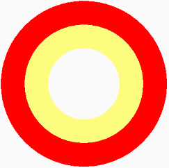
// 画圆
canvas.drawCircle(190,200,150,paint);
// 再画一个圆
paint.setColor(0x7EFFFF00);// 半透明黄色
canvas.drawCircle(190,200,100,paint);
}
}
代码很简单,首先,写一个类派生自View。派生自View表示当前是一个自定义控件,类似Button、TextView这些控件都是派生自View的。如果我们想像LinearLayout、RelativeLayout这样生成一个容器,则需要派生自ViewGroup。
其实,重写onDraw(Canvas canvas)函数。可以看到,在该函数中,形参是一个Canvas对象,也就是当前控件(BasisView)的画布,所以我们只要调用Canvas的绘图函数,效果就可以直接显示在控件上。
Paint类方法:
void setStyle(Style style)
——————————————————————————
style取值:
Paint.Style.FILL:仅填充内部。
Paint.Style.STROKE:仅描边。
Paint.Style.FILL_AND_STROKE:填充内部和描边。

void setAntiAlias(boolean aa)
—————————————————————————————
aa:true 打开抗锯齿功能。
抗锯齿是依赖算法的,一般在绘制不规则的图形时使用,比如圆形、文字等。在绘制棱角分明的图像时,比如一个矩形、一张位图,是不需要打开抗锯齿功能的。

很明显,在打开抗锯齿功能的情况下,所绘制图像可以产生平滑的边缘。
void setStrokeWidth(float width)
————————————————————————————————
单位:px
当画笔Style样式是STROKE、FILL_AND_STROKE时有效。
2.Canvas使用基础
➀画布背景设置:
void drawColor(int color)
void drawrARGB(int a, int r, int g, int b)
void drawRGB(int r, int g, int b)
——————————————————————————————————————————
A、R、G、B每个颜色分量取值范围0~255(0x00~0xFF)
比如将默认填充为紫色:
protected void onDraw(Canvas canvas) {
    super.onDraw(canvas);
    canvas.drawRGB(255, 0, 255);
    // canvas.drawRGB(0xFF, 0, 0xFF); 十六进制更直观
}
➁画直线
void drawLine(float startX, float startY, float stopX, float stopY, Paint paint)
————————————————————————————————————————————————————————————————————————————————
startX:起始点X坐标
startY:起始点Y坐标
stopX:终点X坐标
stopY:终点Y坐标
Paint paint = new Paint();
paint.setColor(Color.RED);
paint.setStyle(Paint.Style.FILL_AND_STROKE);// 此行可省略
paint.setStrokeWidth(50);

canvas.drawLine(100, 100, 200, 200, paint);
注:直线的粗细与画笔Style是没有关系的,上面代码中Style是FILL、STROKE、FILL_AND_STROKE效果一样。粗细只与setStrokeWidth有直接关系。
多条直线:
void drawLines(float[] pts, Paint paint)
• pts:点的集合。这里不是形成连接线,而是每两个点形成一条直线,
       pts的组织方式为{x1, y1, x2, y2, x3, y3, ...}
@Override
    protected void onDraw(Canvas canvas) {
        super.onDraw(canvas);
        Paint paint = new Paint();
        paint.setColor(Color.RED);
        paint.setStrokeWidth(5);
        float[] pts = {10,10, 100,100, 200,200, 400,400};
        canvas.drawLines(pts, paint);
    }

void drawLines(float[] pts, int offset, int count, Paint paint)
• offset:集合中跳过的数值个数。
• count:参与绘制的数值个数,指pts数组中数值的个数。
@Override
    protected void onDraw(Canvas canvas) {
        super.onDraw(canvas);
        Paint paint = new Paint();
        paint.setColor(Color.RED);
        paint.setStrokeWidth(5);
        float[] pts = {10,10, 100,100, 200,200, 400,400};
        canvas.drawLines(pts, 2,4, paint);
    }

offset=2:跳过两个数值10、10;count=4:有4个数值参与绘图。也就是点(100,100)和(200,200),所以效果是这两点连线。
➂点
void drawPoint(float x, float y, Paint paint)
Paint paint = new Paint();
paint.setColor(Color.RED);
paint.setStrokeWidth(15);
canvas.drawPoint(100, 100, paint);
在(100,100)位置画一个点。同样,点的大小只与paint.setStrokeWidth(width)有关,而与paint.setStyle无关。

多个点:
void drawPoints(float[] pts, Paint paint)
void drawPoints(float[] pts, int offset, int count, Paint paint)
@Override
    protected void onDraw(Canvas canvas) {
        super.onDraw(canvas);
        Paint paint = new Paint();
        paint.setColor(Color.RED);
        paint.setStrokeWidth(5);
        float[] pts = {10,10, 100,100, 200,200, 400,400};
        canvas.drawPoints(pts, 2,4, paint);
    }
 即跳过了点(10,10),也没画第四个点(400,400)
➃矩形工具类RectF、Rect概述
RectF与Rect唯一不同的是RectF用来保存float类型数值的矩形结构,而Rect用来保存int类型数值的矩形结构。
RectF构造函数:
RectF()
RectF(float left, float top, float right, float bottom)
RectF(RectF r)
RectF(Rect r)
————————————————————————————————————————————————————————
Rect构造函数:
Rect()
Rect(int left, int top, int right, int bottom)
Rect(Rect r)
// 方法一:直接构造
Rect rect = new Rect(10, 10, 100, 100);
// 方法二:间接构造
Rect rect = new Rect();
rect.set(10, 10, 100, 100);
➄绘制矩形
void drawRect(float left, float top, float right, float bottom, Paint paint)
void drawRect(RectF rect, Paint paint)
void drawRect(Rect r, Paint paint)
Paint paint = new Paint();
paint.setColor(Color.RED);
paint.setStyle(Paint.Style.STROKE);
paint.setStrokeWidth(15);
// 直接构造
canvas.drawRect(10, 10, 100, 100, paint);
// 使用RectF构造
paint.setStyle(Paint.Style.FILL);
RectF rect = new RectF(210f, 10f, 300f, 100f);
canvas.drawRect(rect, paint);

圆角矩形:
void drawRoundRect(RectF rect, float rx, float ry, Paint paint)
• rect:要绘制的矩形
• rx:生成圆角的椭圆的X轴半径
• ry:生成圆角的椭圆的Y轴半径
 可见,圆角矩形的圆角其实是由椭圆的一角形成的。
与shape标签不同的是,drawRoundRect()函数不能针对每个角设置对应的椭圆,而只能统一设置4上角对应的椭圆。
@Override
    protected void onDraw(Canvas canvas) {
        super.onDraw(canvas);
        Paint paint = new Paint();
        paint.setColor(Color.RED);
        paint.setStyle(Paint.Style.FILL);
        paint.setStrokeWidth(15);
        RectF rect = new RectF(100,10,300,100);
        canvas.drawRoundRect(rect, 20, 10, paint);
    }
![]()
圆形:
void drawCircle(float cx, float cy, float radius, Paint paint)
• cx:圆心点的X轴坐标
• cy:圆心点的Y轴坐标
• radius:圆的半径
椭圆:(根据矩形来生成)
void drawOval(RectF oval, Paint paint)
• oval:用来生成椭圆的矩形
弧:(根据椭圆来生成)
void drawArc(RectF oval, float startAngle, float sweepAngle, boolean useCenter, Paint paint)
• oval:生成椭圆的矩形
• startAngle:弧开始的角度,以X轴正方向为0°
• sweepAngle:弧持续的角度
• useCenter:是否有弧的两边。true:有两边;false:只有一条弧
@Override
    protected void onDraw(Canvas canvas) {
        super.onDraw(canvas);
        Paint paint = new Paint();
        paint.setColor(Color.RED);
        paint.setStyle(Paint.Style.STROKE);
        paint.setStrokeWidth(5);
        // 带两边
        RectF rect1 = new RectF(10,10,100,100);
        canvas.drawArc(rect1, 0,90,true,paint);
        // 不带两边
        RectF rect2 = new RectF(110,10,200,100);
        canvas.drawArc(rect2, 0,90,false, paint);
    }
![]()

Rect与RectF:
由于Rect、RectF所具有的函数是相同的,只是保存的数值类型不同,所以下面就以Rect为例来进行讲解。
1)判断是否包含某个点
boolean contains(int x, int y)
——————————————————————————————
该函数用于判断点(x, y)是否在当前矩形中。如果在,则返回true,否则返回false。
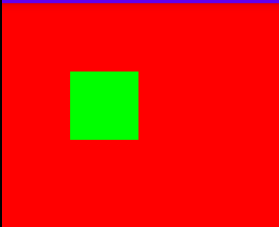
利用这个函数,可以定义一个很简单的控件:绘制一个矩形,当手指在这个矩形区域内时,矩形变为绿色,否则变为红色。
public class BasisView extends View {
    private int mX, mY;
    private Paint mPaint;
    private Rect mRect;

    public BasisView(Context context) {
        super(context);
        init();
    }

    public BasisView(Context context, AttributeSet attrs) {
        super(context, attrs);
        init();
    }

    public BasisView(Context context, AttributeSet attrs, int defStyle) {
        super(context, attrs, defStyle);
        init();
    }

    private void init() {
        mPaint = new Paint();
        mPaint.setStyle(Paint.Style.STROKE);
        mRect = new Rect(100, 10, 300, 100);
    }

    @Override
    public boolean onTouchEvent(MotionEvent event) {
        mX = (int) event.getX();
        mY = (int) event.getY();
        if (event.getAction() == MotionEvent.ACTION_DOWN) {
            invalidate();
            return true;// return True if the event was handled, false otherwise.
        } else if (event.getAction() == MotionEvent.ACTION_UP) {
            mX = -1;
            mY = -1;
        }
        postInvalidate();
        return super.onTouchEvent(event);
    }

    @Override
    protected void onDraw(Canvas canvas) {
        super.onDraw(canvas);
        if (mRect.contains(mX, mY)) {
            mPaint.setColor(Color.RED);
        } else {
            mPaint.setColor(Color.GREEN);
        }
        canvas.drawRect(mRect, mPaint);
    }
}
![]()
在手指按下时,我们需要让屏幕重绘,因为如果当用户点击位置在矩形区域内,则需要将矩形变成红色。
if (event.getAction() == MotionEvent.ACTION_DOWN) {
    invalidate();
    return true;
}
值得注意的是:在MotionEvent.ACTION_DOWN中返回true,因为当MotionEvent.ACTION_DOWN消息到来时,系统会判断返回值,当返回true时,表示当前控件已经在拦截(消费)这个消息了,所以后续ACTION_MOVE、ACTION_UP消息仍然继续传过来。
Android源码中有注释:@return True if the event was handled, false otherwise.
如果 return false; 则效果如下:

返回false(系统默认返回false),就表示当前控件不处理这个event,那么后续的event:ACTION_DOWN、ACTION_MOVE、ACTION_UP等消息就不会再传到这个控件。
最后,调用postInvalidate()函数刷新控件屏幕,让控件重绘。
在ACTION_DOWN消息到来时,我们调用了invalidate()函数重绘控件。其实,postInvalidate()和invalidate()函数都是用来重绘控件的,区别是invalidate()函数一定要在主线程中执行,否则就会报错;而postInvalidate()函数可以在任意线程中执行。因为postInvalidate()函数中就是利用handler给主线程发送刷新界面的消息来实现的,所以它可以在任何线程中执行而不会出错。而正因为它是通过发送消息来实现的,所以它的界面刷新速度可能没有直接调用invalidate()函数那么快。因此,在确定当前线程是主线程的情况下,还是以invalidate()函数为主。当我们不确定当前要刷新的界面的位置所处的线程是不是主线程的时候,还是调用postInvalidate()函数为好;这里故意调用postInvalidate()函数,因为onTouchEvent()函数本来就是在主线程中的,所以使用invalidate()函数更合适。
2)判断是否包含某个矩形
Boolean contains(int left, int top, int right, int bottom)
boolean contains(Rect r)
3)判断两个矩形是否相交
static boolean intersects(Rect a, Rect b)// 静态方法
boolean intersects(int left, int top, int right, int bottom)// 成员方法
静态方法:
Boolean interset1_2 = Rect.intersects(rect_1, rect_2);
成员方法:
Rect rect_1 = new Rect(10, 10, 200, 200);
Boolean interset1_2 = rect_1.intersects(190, 10, 250, 200);
判断相交并返回相交结果:
boolean intersect(int left, int top, int right, int bottom)
boolean intersect(Rect r)
这两成员方法与intersects()方法的区别是,intersect()不仅会返回是否相交的结果,而且会把相交部分的矩形赋给当前Rect对象。如果两个矩形不相交,则当前Rect对象值不变。
@Override
    protected void onDraw(Canvas canvas) {
        super.onDraw(canvas);
        Rect rect_1 = new Rect(10,10,200,200);
        boolean result_1 = rect_1.intersects(190,10,250,200);
        printResult(result_1, rect_1);
        boolean result_2 = rect_1.intersect(210,10,250,200);
        printResult(result_2, rect_1);
        boolean result_3 = rect_1.intersect(190,10,250,200);
        printResult(result_3, rect_1);
    }

    private void printResult(Boolean result, Rect rect) {
        Log.d("result", rect.toShortString() + " result=" + result);
    }
打印日志:
D/result: [10,10][200,200] result=true
D/result: [10,10][200,200] result=false
D/result: [190,10][200,200] result=true
很显然,intersects()函数只是判断是否相交,并不会改变原矩形rect_1的值。当intersect()函数判断的两个矩形不相交时,也不会改变rect_1的值;只有相交时,才会把结果赋给rect_1。
4)合并
合并两个矩形:
合并两个矩形的意思就是将两个矩形合并成一个矩形,即无论这两个矩形是否相交。取两个矩形最小左上角点为结果矩形左上角,取两个矩形最大右下角点为结果矩形的右下角。如果合并两矩形中有一方为空,则将有值的一方作为结果。
public void union(int left, int top, int right, int bottom)
public void union(Rect r)
合并后的结果将会被赋给当前的rect变量。
@Override
    protected void onDraw(Canvas canvas) {
        super.onDraw(canvas);
        Paint paint = new Paint();
        paint.setStyle(Paint.Style.STROKE);
        paint.setStrokeWidth(5);
        Rect rect_1 = new Rect(10,10,20,20);
        Rect rect_2 = new Rect(100,100,110,110);
        // 分别画出原矩形rect_1、rect_2
        paint.setColor(Color.RED);
        canvas.drawRect(rect_1, paint);
        paint.setColor(Color.GREEN);
        canvas.drawRect(rect_2, paint);
        // 画出合并之后的结果rect_1
        paint.setColor(Color.BLUE);
        rect_1.union(rect_2);
        canvas.drawRect(rect_1, paint);
    }

合并矩形与某个点:
public void union(int x, int y)
先判断当前矩形与目标矩形合并点的关系,如果不相交,则根据目标点(x,y)的位置,将目标点设置为当前矩形的左上角点或者右下角点。如果当前矩形是一个空矩形,则最后的结果矩形为([0,0],[x,y])。
@Override
    protected void onDraw(Canvas canvas) {
        super.onDraw(canvas);
        Rect rect_1 = new Rect(10,10,20,20);
        rect_1.union(100,100);
        Log.d("result", rect_1.toShortString());

        rect_1 = new Rect();
        rect_1.union(100,100);
        Log.d("result", rect_1.toShortString());
    }
D/result: [10,10][100,100]
D/result: [0,0][100,100]
3.Color
➀带有透明度的颜色
static int argb(int alpha, int red, int green, int blue)
————————————————————————————————————————————————————————
其中,每个分量取值0~255(0x00~0xFF)
argb()函数的具体实现:
public static int argb(int alpha, int red, int green, int blue) {
    return (alpha << 24) | (red << 16) | (green << 8) | blue;
}
255的二进制表示为:11111111(8个1),如果要表示白色,即各分量都为255,则:
对于各分量取255(11111111),如下:
alpha << 24:11111111 00000000 00000000 00000000
  red << 16:00000000 11111111 00000000 00000000
 green << 8:00000000 00000000 11111111 00000000
       blue:00000000 00000000 00000000 11111111
利用位或“|”运算符,则各分量合并的结果就是ARGB= 11111111 11111111 11111111 11111111
➁不带透明度的颜色
static int rgb(int red, int green, int blue)
➂提取分量颜色
static int alpha(int color)
static int red(int color)
static int green(int color)
static int blue(int color)
比如获取green颜色分量:int green = Color.green(0xFF000F00); green的值就为0x0F
注:
在onDraw()函数中不能创建变量!因为当需要重绘时就会调用onDraw()函数,所以onDraw()函数中创建的变量会一直被重复创建,这样会引起频繁的程序GC(回收内存),进而引起程序卡顿。一般在自定义控件的构造函数中创建变量,即在初始化时一次性创建。
二、路径
在Android中,Path类就代表路径。在Canvas中绘制路径的方法如下:
void drawPath(Path path, Paint paint)
➀直线路径
void moveTo(float startX, float startY)
void lineTo(float endX, float endY)// 再次调用起点就是:(endX, endY)了。
void close()// 如果连续画了几条直线,没有形成闭环,此函数会将路径首尾连接起来形成闭环。
Paint paint = new Paint();
paint.setColor(Color.RED);
paint.setStyle(Paint.Style.STROKE);
paint.setStrokeWidth(5);

Path path = new Path();
path.moveTo(10, 10);
path.lineTo(10, 100);
path.lineTo(300, 100);
path.close();

canvas.drawPath(path, paint);

➁弧线路径
void arcTo(RectF oval, float startAngle, float sweepAngle)
——————————————————————————————————————————————————————————
弧线是从椭圆上截取的一部分。
RectF oval:生成椭圆的矩形。
float startAngle:弧开始的角度,以X轴正方向为0°
float sweepAngle:弧持续的角度。
Path path = new Path();
RectF rectF = new RectF(100,10,200,100);
path.arcTo(rectF, 0, 359.9f);
canvas.drawPath(path, paint);
![]()
在默认情况下路径都是连贯的,除以下两种情况外:
• 调用addXXX系列函数,将直接添加固定形状的路径。
• 调用moveTo函数改变绘制起始位置。
@Override
protected void onDraw(Canvas canvas) {
    super.onDraw(canvas);
    Paint paint = new Paint();
    paint.setColor(Color.RED);
    paint.setStyle(Paint.Style.FILL);
    // paint.setStyle(Paint.Style.Stroke);
    paint.setStrokeWidth(5);

    Path path = new Path();
    path.moveTo(10, 10);
    RectF rectF = new RectF(100, 10, 200, 100);
    path.arcTo(rectF, 0, 180);
    canvas.drawPath(path, paint);
}
 解注释并注释上一行:
如果我们不想连接怎么办?Path类也提供了另外两个重载方法:
void arcTo(float left, float top, float right, float bottom, float startAngle, float sweepAngle, boolean forceMoveTo);
void arcTo(RectF oval, float startAngle, float sweepAngle, boolean forceMoveTo);
如果参数forceMoveTo==true,会与addArc方式相同,以一个新的轮廓添加到path中。
@Override
protected void onDraw(Canvas canvas) {
    super.onDraw(canvas);
    Paint paint = new Paint();
    paint.setColor(Color.RED);
    paint.setStyle(Paint.Style.STROKE);
    paint.setStrokeWidth(5);

    Path path = new Path();
    path.moveTo(10, 10);
    RectF rectF = new RectF(100, 10, 200, 100);
    path.arcTo(rectF, 0, 180, true);
    canvas.drawPath(path, paint);
}

addXXX系列函数:
add即“添加”,即直接往Path中添加一些曲线,而不必考虑连贯性。
@Override
    protected void onDraw(Canvas canvas) {
        super.onDraw(canvas);
        Paint paint = new Paint();
        paint.setStyle(Paint.Style.STROKE);
        paint.setStrokeWidth(5);
        paint.setColor(Color.RED);

        Path path = new Path();
        path.moveTo(10,10);
        path.lineTo(100,50);
        RectF rectF = new RectF(100,100,150,150);
        path.addArc(rectF, 0, 90);
        canvas.drawPath(path, paint);
    }

1.添加矩形路径
void addRect(float left, float top, float right, float bottom, Path.Direction dir)
void addRect(RectF rect, Path.Direction dir)
——Path.Direction参数有两个值:
• Path.Direction.CCW:是counter-clockwise的缩写,指创建逆时针方向的矩形路径
• Path.Direction.CW:是clockwise的缩写,指创建顺时针方向的矩形路径
@Override
    protected void onDraw(Canvas canvas) {
        super.onDraw(canvas);
        // 第一条路径逆向生成
        Path CCWRectpath = new Path();
        RectF rect1 = new RectF(50,50,240,200);
        CCWRectpath.addRect(rect1, Path.Direction.CCW);
        // 第二条路径顺向生成
        Path CWRectpath = new Path();
        RectF rect2 = new RectF(290,50,480,200);
        CWRectpath.addRect(rect2, Path.Direction.CW);
        // 画出这两条路径
        Paint paint = new Paint();
        paint.setStyle(Paint.Style.STROKE);
        paint.setStrokeWidth(5);
        paint.setColor(Color.RED);
        canvas.drawPath(CCWRectpath, paint);
        paint.setColor(Color.BLUE);
        canvas.drawPath(CWRectpath, paint);
    }
![]()
路径的大小只与生成路径的矩形大小有关,与生成方向无关。
生成方向是用来做什么的呢?答:用于生成方向排版的文字。
基于上面的矩形,添加文字:
// 依据路径布局文字
String text = "苦心人天不负,有志者事竟成";
paint.setColor(Color.BLUE);
paint.setTextSize(35);
canvas.drawTextOnPath(text, CCWRectpath, 0, 18, paint);// 逆时针
canvas.drawTextOnPath(text, CWRectpath, 0, 18, paint);// 顺时针

2.添加圆角矩形路径
void addRoundRect(RectF rect, float[] radii, Path.Direction dir)
void addRoundRect(RectF rect, float rx, float ry, Path.Direction dir)
• float[] radii:必须传入8个数值,分4组,分别对应每个角所使用的椭圆的横轴半径和纵轴半径,
                 如{rx1,ry1, rx2,ry2, rx3,ry3, rx4,ry4}
• float rx:生成圆角的椭圆的横轴半径
• float ry:生成圆角的椭圆的纵轴半径
@Override
    protected void onDraw(Canvas canvas) {
        super.onDraw(canvas);
        Path path = new Path();
        RectF rect1 = new RectF(50, 50, 240, 200);
        path.addRoundRect(rect1, 10, 15, Path.Direction.CCW);

        RectF rect2 = new RectF(290, 50, 480, 200);
        float radii[] = {10,15, 20,25, 30,35, 40,45};
        path.addRoundRect(rect2, radii, Path.Direction.CCW);

        Paint paint = new Paint();
        paint.setColor(Color.RED);
        canvas.drawPath(path, paint);
    }

3.添加圆形路径
void addCircle(float x, float y, float radius, Path.Direction dir)
• x:圆心X轴坐标
• y:圆心Y轴坐标
• radius:圆半径
Path path = new Path();
path.addCircle(100, 100, 50, Direction.CCW);
canvas.drawPath(path, paint);
4.添加椭圆半径
void addOval(RectF oval, Path.Direction dir)
• oval:生成椭圆的矩形
5.添加弧形路径
void addArc(float left, float top, float right, float bottom, float startAngle, float sweepAngle)
void addArc(RectF oval, float startAngle, float sweepAngle)
Path填充模式:
FillType.WINDING:默认值,当两图形相交时,取相交部分显示
FillType.INVERSE_WINDING:取path的外部区域
FillType.EVEN_ODD:取path所在并不相交的区域
FillType.INVERSE_EVEN_ODD:取path的外部和相交区域
@Override
    protected void onDraw(Canvas canvas) {
        super.onDraw(canvas);
        Paint paint = new Paint();
        paint.setColor(Color.RED);
        paint.setStyle(Paint.Style.FILL);

        Path path = new Path();
        path.addRect(100,100,300,300,Path.Direction.CW);
        path.addCircle(300,300,100, Path.Direction.CW);
        path.setFillType(Path.FillType.WINDING);

        canvas.drawPath(path, paint);
    }


重置路径:
当我们需要重绘一条全新的路径时,Android开发人员为了重复利用空间,允许我们重置路径对象。路径对象一旦被重置,其中保存的所有路径都被清空,这样我们就不需要重新定义一个路径对象了。重新定义路径对象的问题在于老对象的回收和新对象的内存分配,当然这些过程都会消耗手机的性能。
void rewind()
void reset()
——————————————
• rewind()函数会清除FillType及所有的直线、曲线、点的数据等,但会保留数据结构。
  这样可以实现快速重用,提高一定的性能。例如,重复绘制一类线段,它们的点的数量都相等,
  那么使用rewind()函数可以保留装载点数据结构,效率会更高。
  一定要注意的是,【只有在【重复绘制相同】路径时】,这些数据结构才是可以复用的。
• reset()函数类似于新建一个路径对象,它的所有数据空间都会被回收并重新分配,但不会清除FillType。
从整体来讲,rewind()函数不会清除内存,但会清除FillType;而reset()函数则会清除内存,但不会清除FillType。
@Override
    protected void onDraw(Canvas canvas) {
        super.onDraw(canvas);
        Paint paint = new Paint();
        paint.setColor(Color.RED);

        Path path = new Path();
        path.setFillType(Path.FillType.INVERSE_WINDING);
        path.reset();
        path.addCircle(100, 100, 50, Path.Direction.CW);
        canvas.drawPath(path, paint);
    }
 注释掉path.reset();效果一样。 path.reset();换成path.rewind(); ->
  (清除掉了FillType,使用默认的FillType)
示例:蜘蛛网状图
public class BasisView extends View {
    private int count = 6; //数据个数
    private float radius; //网格最大半径
    private int centerX; //中心X
    private int centerY; //中心Y
    private Paint radarPaint, valuePaint;
    //计算出每个夹角的度数
    private float angle = (float) (Math.PI * 2 / count);
    //数据
    private double[] data = {2, 5, 1, 6, 4, 5};
    private float maxValue = 6; //最大值

    public BasisView(Context context, AttributeSet attrs) {
        super(context, attrs);
        init();
    }

    private void init() {
        radarPaint = new Paint();
        radarPaint.setStyle(Paint.Style.STROKE);
        radarPaint.setColor(Color.GREEN);

        valuePaint = new Paint();
        valuePaint.setColor(Color.BLUE);
        valuePaint.setStyle(Paint.Style.FILL);
    }

    @Override
    protected void onSizeChanged(int w, int h, int oldw, int oldh) {
        radius = Math.min(h, w) / 2 * 0.9f;
        //中心坐标
        centerX = w / 2;
        centerY = h / 2;
        postInvalidate();// 控件大小发生改变,通知重绘
        super.onSizeChanged(w, h, oldw, oldh);
    }

    /**
     * 绘制正多边形
     */
    private void drawPolygon(Canvas canvas) {
        Path path = new Path();
        float r = radius / count;// r是蜘蛛丝之间的间距
        for (int i = 1; i <= count; i++) {// 中心点不用绘制
            float curR = r * i;// 当前半径
            path.reset();
            for (int j = 0; j < count; j++) {
                if (j == 0) {
                    path.moveTo(centerX + curR, centerY);
                } else {
                    //根据半径,计算出蜘蛛丝上每个点的坐标
                    float x = (float) (centerX + curR * Math.cos(angle * j));
                    float y = (float) (centerY + curR * Math.sin(angle * j));
                    path.lineTo(x, y);
                }
            }
            path.close();//闭合路径
            canvas.drawPath(path, radarPaint);
        }
    }

    /**
     * 绘制直线
     */
    private void drawLines(Canvas canvas) {
        Path path = new Path();
        for (int i = 0; i < count; i++) {
            path.reset();
            path.moveTo(centerX, centerY);
            float x = (float) (centerX + radius * Math.cos(angle * i));
            float y = (float) (centerY + radius * Math.sin(angle * i));
            path.lineTo(x, y);
            canvas.drawPath(path, radarPaint);
        }
    }

    /**
     * 绘制区域
     * @param canvas
     */
    private void drawRegion(Canvas canvas) {
        Path path = new Path();
        valuePaint.setAlpha(127);
        for (int i = 0; i < count; i++) {
            double percent = data[i] / maxValue;
            float x = (float) (centerX + radius * Math.cos(angle * i) * percent);
            float y = (float) (centerY + radius * Math.sin(angle * i) * percent);
            if (i == 0) {
                path.moveTo(x, centerY);
            } else {
                path.lineTo(x, y);
            }
            //绘制小圆点
            canvas.drawCircle(x, y, 10, valuePaint);
        }
        //绘制填充区域
        valuePaint.setStyle(Paint.Style.FILL_AND_STROKE);
        canvas.drawPath(path, valuePaint);
    }

    @Override
    protected void onDraw(Canvas canvas) {
        super.onDraw(canvas);
        drawPolygon(canvas);// 绘制蛛蛛网格
        drawLines(canvas);// 画网格中线
        drawRegion(canvas);// 画数据图
    }
}

protected void onSizeChanged (int w, int h, int oldw, int oldh)
————————————————————————————————————————————————————————————————
This is called during layout when the size of this view has changed.
If you were just added to the view hierarchy, you're called with the old values of 0.
• w:Current width of 【this view】.
• h:Current height of 【this view】.
• oldw:Old width of this view.
• oldh:Old height of this view.
onSizeChanged()函数中,根据View的长、宽,获取整个布局的中心坐标,因为整个雷达都是从这个中心坐标开始绘制的。
我们知道,在控件大小发生变化时,都会通过onSizeChanged()函数通知我们当前控件的大小。所以,我们只需要重写onSizeChanged()函数,即可得知当前控件的最新大小。
因为蛛蛛网的总大小占当前控件大小的90%,所以,我们将蛛蛛网的半径设置为Math.min(h,w)*0.9f。
三、文字
paint设置:
Paint与文字相关的设置方法:
// 普通设置
paint.setStrokeWidth(5);
paint.setAntiAlias(true);// 如果使用抗锯齿,则会使绘图速度变慢
paint.setStyle(Paint.Style.FILL);
paint.setTextAlign(Align.CENTER);// 文字对齐方式:CENTER、LEFT、RIGHT
paint.setTextSize(12);
// 样式设置
paint.setFackBoldText(true);// 设置是否为粗体文字
paint.setUnderlineText(true);
paint.setTextSkewX((float) -0.25);// 设置字体水平倾斜度,普通斜体字设为-0.25
paint.setStrikeThruText(true);// 设置带有删除线效果
// 其他设置
paint.setTextScaleX(2);// 只会将水平方向拉伸,高度不变
1.填充样式的区别
@Override
    protected void onDraw(Canvas canvas) {
        super.onDraw(canvas);
        Paint paint = new Paint();
        paint.setColor(Color.RED);
        paint.setStrokeWidth(5);
        paint.setAntiAlias(true);
        paint.setTextSize(90);
        paint.setStyle(Paint.Style.STROKE);
        canvas.drawText("床前明月光", 10, 100, paint);
    }
![]()

2.setTextAlign()函数
public void setTextAlign(Align align)
参数align的取值如下:
• Align.LEFT:居左绘制
• Align.CENTER:居中绘制,即通过drawText()函数指定的起始点在文字中间位置
• Align.RIGHT:居右绘制,即通过drawText()函数指定的【起始点】【在文字右侧位置】
paint.setStrokeWidth(5);
paint.setAntiAlias(true);
paint.setTextSize(80);
paint.setTextAlign(Paint.Align.RIGHT);
canvas.drawText("床前明月光", 400, 100, paint);

Canvas绘制文本:
1.普通绘制
void drawText(String text, float x, float y, Paint paint)
• (x,y):起始点坐标
——————————————————————————————————————————————————————————
void drawText(CharSequence text, int start, int end, float x, float y, Paint paint)
void drawText(String text, int start, int end, float x, float y, Paint paint)
• start:起始绘制字符所在字符串中的索引
• end:结束绘制字符所在字符串中的索引
• (x,y):起始点坐标
————————————————————————————————————————————————————————————————————————————————————
void drawText(char[] text, int index, int count, float x, float y, Paint paint)
• index:指定起始绘制字符的位置
• count:指定从起始绘制字符开始绘制几个字符
• (x,y):起始点坐标
@Override
    protected void onDraw(Canvas canvas) {
        super.onDraw(canvas);
        Paint paint = new Paint();
        paint.setColor(Color.RED);
        paint.setTextSize(80);
        canvas.drawText("床前明月光", 2, 4, 10, 100, paint);
    }

2.逐个指定文字位置
void drawPosText(String text, float[] pos, Paint paint)
void drawPosText(char[] text, int index, int count, float[] pos, Paint paint)
• index:第一个要绘制的文字的索引
• count:要绘制的文字的个数,用来计算最后一个文字的位置
• float[] pos:要绘制的每个文字的具体位置,同样两两一组,如{x1,y1, x2,y2, x3,y3,...}
@Override
    protected void onDraw(Canvas canvas) {
        super.onDraw(canvas);
        Paint paint = new Paint();
        paint.setColor(Color.RED);
        paint.setTextSize(80);
        float[] pos = {80,100, 80,200, 80,300, 80,400};
        canvas.drawPosText("床前明月", pos, paint);
    }
![]()
3.沿路径绘制
void drawTextOnPath(String text, Path path, float hOffset, float vOffset, Paint paint)
void drawTextOnPath(char[] text, int index, int count, Path path, float hOffset, float vOffset, Paint paint)
• hOffset:与路径起始点的水平偏移量
• vOffset:与路径中心的垂直偏移量
@Override
    protected void onDraw(Canvas canvas) {
        super.onDraw(canvas);
        Paint paint = new Paint();
        paint.setColor(Color.RED);
        paint.setStrokeWidth(5);
        paint.setStyle(Paint.Style.STROKE);
        // 先创建两条相同的图形路径,并画出两条路径原形
        Path circlePath = new Path();
        circlePath.addCircle(220,300,150, Path.Direction.CCW);// 逆时针
        canvas.drawPath(circlePath, paint);

        Path circlePath2 = new Path();
        circlePath2.addCircle(600,300,150, Path.Direction.CCW);
        canvas.drawPath(circlePath2, paint);
        // 绘制原始文字与偏移文字
        String string = "床前明月光,疑是地上霜";
        paint.setColor(Color.GREEN);
        paint.setTextSize(50);
        // 将hOffset、vOffset参数值全部设为0,看原始状态是怎样的
        canvas.drawTextOnPath(string, circlePath, 0, 0, paint);
        // 改变hOffset、vOffset参数值
        canvas.drawTextOnPath(string, circlePath2, 80, 30, paint);
    }

设置字体样式:
Typeface setTypeface(Typeface typeface)
1.使用系统中的字体样式
1)使用Android自带的字体样式:Typeface.SANS_SERIF、Typeface.MONOSPACE、Typeface.SERIF
Paint paint = new Paint();
paint.setColor(Color.RED);
paint.setTypeface(Typeface.SERIF);
paint.setTextSize(50);
canvas.drawText("床前明月光", 10, 100, paint);
2)defaultFromStyle()函数
Typeface defaultFromStyle(int style)
• Typeface.NORMAL:正常字体
• Typeface.BOLD:粗体
• Typeface.ITALIC:斜体
• Typeface.BOLD_ITALIC:粗斜体
如果系统默认的字体是宋体,那么,当指定defaultFromStyle(Typeface.BOLD_ITALIC)时,获取的将是粗斜体的宋体样式。
3)create(String familyName, int style)函数
Typeface create(String familyName, int style)
——————————————————————————————————————————————
该函数直接通过指定字体名来加载系统中自带的字体样式。
如果字体样式不存在,则会用系统样式替代返回。
Paint paint = new Paint();
paint.setColor(Color.RED);
paint.setTextSize(50);

String familyName = "宋体";
Typeface font = Typeface.create(familyName, Typeface.NORMAL);
paint.setTypeface(font);
canvas.drawText("床前明月光", 10, 100, paint);
2.自定义字体样式
Typeface createFromAsset(AssetManager mgr, String path)
Typeface createFromFile(String path)
Typeface createFromFile(File path)
// 自定义字体,迷你简萝卜
Paint paint = new Paint();
paint.setColor(Color.BLACK);
paint.setTextSize(60);

AssetManager mgr = mContext.getAssets();
Typeface typeface = Typeface.createFromAsset(mgr, "fonts/jian_luobo.ttf");
paint.setTypeface(typeface);
canvas.drawText("床前明月光,疑是地上霜", 10, 100, paint);
![]()
四、Region
Region,顾名思义,区域是一块任意形状的封闭图形。
1.直接构造
public Region(Region region) // 复制一个Region的范围
public Region(Rect r) // 创建一个矩形区域
public Region(int left, int top, int right, int bottom) // 创建一个矩形区域
@Override
    protected void onDraw(Canvas canvas) {
        super.onDraw(canvas);
        Paint paint = new Paint();
        paint.setColor(Color.RED);
        paint.setStyle(Paint.Style.FILL);

        Region region = new Region(new Rect(50, 50, 200, 100));
        RegionIterator it = new RegionIterator(region);
        Rect r = new Rect();
        while (it.next(r)) {
            canvas.drawRect(r, paint);
        }
    }
![]()
可以看到,Canvas并没有提供针对Region的绘图方法,这就说明Region的本意并不是用来绘图的。
对于上面构造的矩形填充,我们完全可以使用Rect来代替:
Paint paint = new Paint();
paint.setStyle(Paint.Style.FILL);
paint.setColor(Color.RED);
canvas.drawRect(new Rect(50, 50, 200, 100), paint);
2.间接构造
public Region() // Region的空构造函数

set系列函数:
public void setEmpty() // 置空
public boolean set(Region region)
public boolean set(Rect r)
public boolean set(int left, int top, int right, int bottom)
public boolean setPath(Path path, Region clip)
注:无论调用set系统函数的Region是不是有区域值,当调用set系列函数后,原来的区域值就会被替换成set系列函数里的区域值。
各函数的含义如下:
• setEmpty():从某种意义上讲,置空也是一个构造函数,即将原来的一个区域变量变成空变量,再利用其他set函数重新构造区域。
• set(Region region):利用新的区域替换原来的区域。
• set(Rect r):利用矩形所代表的区域替换原来的区域。
• set(int left, int top, int right, int bottom):根据矩形的两个角点构造出矩形区域来替换原来的区域。
• setPath(Path path, Region clip):根据路径的区域与某区域的交集构造出新的区域。
在这里主要讲解利用setPath()函数构造不规则区域的方法,其他的几个函数使用难度都不大,就不再详细讲解。
boolean setPath(Path path, Region clip)
• path:用来构造区域的路径。
• clip:与前面的path所构成的路径取交集,并将该交集设置为最终的区域。
@Override
    protected void onDraw(Canvas canvas) {
        super.onDraw(canvas);
        Paint paint = new Paint();
        paint.setColor(Color.RED);
        paint.setStyle(Paint.Style.FILL);

        Path ovalPath = new Path();
        RectF rect = new RectF(50, 50, 200, 500);
        ovalPath.addOval(rect, Path.Direction.CCW);// CCW:逆时针,CW:顺时针
        Region rgn = new Region();
        rgn.setPath(ovalPath, new Region(50, 50, 200, 200));
        drawRegion(canvas, rgn, paint);
    }

    private void drawRegion(Canvas canvas, Region rgn, Paint paint) {
        RegionIterator it = new RegionIterator(rgn);
        Rect r = new Rect();
        while(it.next(r)){
            canvas.drawRect(r, paint);
        }
    }
 (注:只显示红色区域,其他是辅助线)。Paint.Style.FILL改为STROKE,效果:
枚举区域——RegionIterator类
一定数量的矩形所合成的形状也可以代表区域的形状。Regioniterator类就实现了获取组成区域的矩形集的功能。
RegionIterator(Region region) // 根据区域构建对应的矩形集
boolean next(Rect r) // 获取下一个矩形,将结果保存在参数Rect r中
由于在Canvas中没有直接绘制Region的函数,想要绘制一个区域,就只能通过RegionIterator类构造矩形集来逼近显示区域,所以drawRegion()函数的具体实现如下:
private void drawRegion(Canvas canvas, Region rgn, Paint paint){
    RegionIterator it = new RegionIterator(rgn);
    Rect r = new Rect();
    while (it.next(r)) {
        canvas.drawRect(r, paint);
    }
}
首先根据区域构造一个矩形集,然后利用next(Rect r)函数来逐个获取所有矩形并绘制出来,最终得到的就是整个区域。如果我们想画一个椭圆区域,并且把画笔样式从FILL改为STROKE,则效果更清楚。
@Override
    protected void onDraw(Canvas canvas) {
        super.onDraw(canvas);
        Paint paint = new Paint();
        paint.setColor(Color.RED);
        paint.setStyle(Paint.Style.STROKE);
        // 构造一条椭圆路径
        Path ovalPath = new Path();
        RectF rect = new RectF(50,50,200,500);
        ovalPath.addOval(rect, Path.Direction.CCW);
        // 构造椭圆区域
        Region rgn = new Region();
        rgn.setPath(ovalPath, new Region(50,50,200,500));
        drawRegion(canvas, rgn, paint);
    }

在代码中,同样先构造了一条椭圆路径,然后在形成Region时传入一个与构造的椭圆区域相同大小的矩形,所以取交集之后的结果就是椭圆路径所对应的区域。
用paint把区域画出来,而paint的样式是STROKE,就是用描边的方式来画这个区域。如果用样式是FILL,则就是一个红色椭圆。
从效果图可以明显看出,在绘制Region对象时,其实就是先将其转换成矩形集,然后利用画笔将每个矩形画出来而已。
区域相交:
1.union()函数
boolean union(Rect r) // 与指定矩形并集
Region不是用来绘图的,所以Region最重要的功能在区域的相交操作中。
Paint paint = new Paint();
paint.setColor(Color.RED);
paint.setStyle(Paint.Style.FILL);

Region region = new Region(10, 10, 200, 100);
region.union(new Rect(10, 10, 50, 300));
drawRegion(canvas, region, paint);

2.区域操作
系列方法一:
boolean op(Rect r, Op op)
boolean op(int left, int top, int right, int bottom, Op op)
boolean op(Region region, Op op)
用当前Region对象与指定的一个Rect对象或者Region对象执行相交操作,将将结果赋给当前的Region对象。如果计算成功,返回true,否则返回false。
public enum Op {
    DIFFERENCE(0),         region1与region2补集(region1-region2的区域)
    INTERSECT(1),          region1与region2交集
    UNION(2),              region1与region2并集
    XOR(3),                region1与region2异并集(相交之外的区域)
    REVERSE_DIFFERENCE(4), region2与region1补集(region2-region1的区域)
    REPLACE(5),            region2区域(替换)
}

@Override
    protected void onDraw(Canvas canvas) {
        super.onDraw(canvas);
        Paint paint = new Paint();
        paint.setColor(Color.RED);
        paint.setStyle(Paint.Style.STROKE);
        paint.setStrokeWidth(2);
        // 构造两个矩形轮廓
        Rect rect1 = new Rect(100,100,400,200);
        Rect rect2 = new Rect(200,0,300,300);
        canvas.drawRect(rect1, paint);
        canvas.drawRect(rect2, paint);
        // 构造两个区域
        Region region = new Region(rect1);
        Region region2 = new Region(rect2);
        // 取两个区域的交集
        region.op(region2, Region.Op.INTERSECT);
        // 构造一个填充画笔,将所选区域用绿色填充
        Paint paint_fill = new Paint();
        paint_fill.setColor(Color.GREEN);
        paint_fill.setStyle(Paint.Style.FILL);
        drawRegion(canvas, region, paint_fill);
    }

系列方法二:
boolean op(Rect rect, Region region, Op op)
boolean op(Region region1, Region region2, Op op)
Region region1 = new Region(100, 100, 400, 200);
Region region2 = new Region(200, 0, 300, 300);

Region region = new Region();
region.op(region1, region2, Region.Op.INTERSECT);
在这里,将region1、region2相交的结果赋给Region对象。
其他函数:
1.几个判断方法
public boolean isEmpty() // 判断该区域是否为空
public boolean isRect() // 判断该区域是否是一个矩阵
public boolean isComplex() // 判断该区域是否是多个矩阵的组合
2.getBound系列函数:
public Rect getBounds()
public boolean getBounds(Rect r)
————————————————————————————————
用于返回能够包裹当前路径的最小矩形
public Path getBoundaryPath()
public boolean getBoundaryPath(Path path)
——————————————————————————————————————————
用于返回当前矩形所对应的Path对象
3.是否包含
public boolean contains(int x, int y)
——————————————————————————————————————
用于判断该区域是否包含某个点
public boolean quickContains(Rect r)
public boolean quickContains(int left, int top, int right, int bottom)
——————————————————————————————————————————————————————————————————————
用于判断该区域是否包含某个矩形
4.是否相交
public boolean quickReject(Rect r)
public boolean quickReject(int left, int top, int right, int bottom)
————————————————————————————————————————————————————————————————————
用于判断该区域是否没有和指定矩形相交
public boolean quickReject(Region rgn)
——————————————————————————————————————
用于判断该区域是否没有和指定区域相交
5.平移变换
public void translate(int dx, int dy)
——————————————————————————————————————
用于将Region对象向X轴平移dx距离,向Y轴平移dy距离,并将结果赋给当前Region对象。
X轴向右是正方向,Y轴向下是正方向。
public void translate(int dx, int dy, Region dst)
—————————————————————————————————————————————————
用于将Region对象向X轴平移dx距离,向Y轴平移dy距离。
将结果赋给dst对象,而当前Region对象的值保持不变。
五、Canvas(画布)
Canvas变换
1.平移(Translate)
void translate(float dx, float dy)
• dx:水平方向平移的距离,正数为向正方向(向右)平移的量,负数为向负方向(向左)平移的量。
• dy:垂直方向平移的距离,正数为向正方向(向下)平移的量,负数为向负方向(向上)平移的量。
@Override
    protected void onDraw(Canvas canvas) {
        super.onDraw(canvas);
        Paint paint = new Paint();
        paint.setColor(Color.GREEN);
        paint.setStyle(Paint.Style.FILL);

        canvas.translate(100, 100);
        Rect rect1 = new Rect(0,0,400,200);
        canvas.drawRect(rect1, paint);
    }

2.屏幕显示与Canvas的关系
@Override
    protected void onDraw(Canvas canvas) {
        super.onDraw(canvas);
        // 构造两个画笔,一个红色,一个绿色
        Paint paint_green = generatePaint(Color.GREEN, Paint.Style.STROKE, 3);
        Paint paint_red = generatePaint(Color.RED, Paint.Style.STROKE, 3);
        // 构造一个矩形
        Rect rect1 = new Rect(0, 0, 400, 220);
        // 平移画布前,用绿色画笔画下边框
        canvas.drawRect(rect1, paint_green);
        // 平移画布后,用红色画笔画下边框
        canvas.translate(100, 100);
        canvas.drawRect(rect1, paint_red);
    }

    private Paint generatePaint(int color, Paint.Style style, int width) {
        Paint paint = new Paint();
        paint.setColor(color);
        paint.setStyle(style);
        paint.setStrokeWidth(width);
        return paint;
    }

很多人一直认为显示所绘图形的屏幕就是Canvas,其实这是一种非常错误的理解。以上绿色边框为什么没有移动?这是由于屏幕显示与Canvas根本不是一个概念!Canvas是一个很虚幻的概念,相当于一个透明图层。每次在Canvas上画图时(调用drawXXX系列函数),都会先产生一个透明图层,然后在这个图层上画图,画完之后覆盖在屏幕上显示。


下面对上述知识做一下总结:
(1)当每次调用drawXXX系列函数来绘图时,都会产生一个全新的Canvas透明图层。
(2)如果在调用drawXXX系列函数前,调用平移、旋转等函数对Canvas进行了操作,那么这个操作是不可逆的。每次产生的画布的最新位置都是这些操作后的位置。
(3)在Canvas图层与屏幕合并时,超出屏范围的图像是不会显示出来的。
3.旋转(Rotate)
画布的旋转默认是围绕坐标原点来进行的。这里容易产生错觉,看起来是图片旋转了,其实我们旋转的是画布,以后在此画布上绘制的图形显示出来的时候看起来都是旋转的。
void rotate(float degrees)
void rotate(float degrees, float px, float py)
• degrees:旋转中心点是原点(0,0),旋转的度数,正数顺时针旋转,负数逆时针旋转
• (px,py):指定旋转的中心点坐标(px,py)
@Override
    protected void onDraw(Canvas canvas) {
        super.onDraw(canvas);
        Paint paing_green = generatePaint(Color.GREEN, Paint.Style.FILL, 5);
        Paint paing_red = generatePaint(Color.RED, Paint.Style.STROKE, 5);

        Rect rect1 = new Rect(300,10,500,100);
        canvas.drawRect(rect1, paing_red);

        canvas.rotate(30);
        canvas.drawRect(rect1, paing_green);
    }

第一次合成过程,画出原轮廓:

第二次合成过程,先将Canvas沿正方向依原点旋转30°,再与上面的屏幕合成,最后显示出复合效果。

4.缩放(Scale)
public void scale(float sx, float sy)
public void scale(float sx, float sy, float px, float py)
——————————————————————————————————————————————————————————
用于变更坐标轴密度
• sx:水平方向伸缩比例。假设原坐标轴比例为n,不变时为1,变更后X轴密度为 n × sx。
      sx是小数表示缩小,sx是整数表示放大。
• sy:垂直方向伸缩比例。
• (px,py):缩放中心坐标为(px,py)
@Override
protected void onDraw(Canvas canvas) {
    super.onDraw(canvas);
    Paint paint_green = generatePaint(Color.GREEN, Style.STROKE, 5);
    Paint paint_red = generatePaint(Color.RED, Style.STROKE, 5);
    Rect rect1 = new Rect(10, 10, 200, 100);
    canvas.drawRect(rect1, paint_green);
    canvas.scale(0.5f, 1);
    canvas.drawRect(rect1, paint_red);
}
 图中,绿框是原坐标轴密度图形,红框是X轴密度缩小到0.5倍之后显示的图形。
5.扭曲(Skew)
void skew(float sx, float sy)
• sx:将画布在X轴方向上倾斜相应的角度,sx为倾斜角度的正切值
• sy:将画布在Y轴方向上倾斜相应的角度,sy为倾斜角度的正切值
注:倾斜角度的正切值,比如在X轴方向上倾斜60°,tan60=1.732
@Override
    protected void onDraw(Canvas canvas) {
        super.onDraw(canvas);
        Paint paint_green = generatePaint(Color.GREEN, Paint.Style.STROKE, 5);
        Paint paint_red = generatePaint(Color.RED, Paint.Style.STROKE, 5);
        Rect rect1 = new Rect(10, 10, 200, 100);
        canvas.drawRect(rect1, paint_green);
        canvas.skew(1.732f, 0);// X轴倾斜60°,Y轴不变
        canvas.drawRect(rect1, paint_red);
    }
![]()
6.裁剪画布(clip系列函数)
裁剪画布是指利用clip系列函数,通过与Rect、Path、Region取交、并、差等集合运算来获取最新的画布形状。除调用save()、restore()函数外,这个操作是不可逆的,一旦Canva被裁剪,就不能恢复。
注:在使用裁剪画布系列函数时,需要禁用硬件加速功能。
setLayerType(LAYER_TYPE_SOFTWARE, null);
裁剪画布系列函数:
boolean clipPath(Path path)
boolean clipPath(Path path, Region.Op op)
boolean clipRect(Rect rect, Region.Op op)
boolean clipRect(RectF rect, Region.Op op)
boolean clipRect(int left, int top, int right, int bottom)
boolean clipRect(float left, float top, float right, float bottom)
boolean clipRect(RectF rect)
boolean clipRect(float left, float top, float right, float bottom, Region.Op op)
boolean clipRect(Rect rect)
boolean clipRegion(Region region)
boolean clipRegion(Region region, Region.Op op)
@Override
    protected void onDraw(Canvas canvas) {
        super.onDraw(canvas);
        canvas.drawColor(Color.RED);
        canvas.clipRect(new Rect(100, 100, 200, 200));
        canvas.drawColor(Color.GREEN);
    }
先把背景涂成红色,显示在屏幕上;然后裁剪画布;最后将最新的画布涂成绿色。可见,绿色部分只有一小块,而不再是整个屏幕了。
画布的保存与恢复
1.save()和restore()函数
前面介绍所有对画布的操作都是不可逆的,这会造成很多麻烦。比如,为了实现一些效果而不得不对画布进行操作,但操作完了,画布状态也改变了,这会严重影响到后面的画图操作。如果能对画布的大小和状态(旋转角度、扭曲等)进行实时保存和恢复就好了。
int save() // 画布保存
int restore() // 画布恢复
• save():每次调用save()函数,都会先保存当前画布的状态,然后将其放入特定的栈中。
• restore():每次调用restore()函数,都会把栈中顶层的画布状态取出来,并按照这个状态恢复当前的画布,然后在这个画布上作画。
@Override
    protected void onDraw(Canvas canvas) {
        super.onDraw(canvas);
        canvas.drawColor(Color.RED);
        // 保存当前画布大小,即整屏
        canvas.save();
        canvas.clipRect(new Rect(100,100,800,800));
        canvas.drawColor(Color.GREEN);
        // 恢复整屏画布(即canvas对象变回为save()时的画布,而不是clip后的画布图层
        canvas.restore();
        Paint paint = generatePaint(Color.BLUE, Paint.Style.STROKE, 5);
        canvas.drawRect(10, 10, 100, 100, paint);
    }

如果不save()、restore()的话,drawRect()方法会在裁剪范围外而画不到画布上去。因为save()的画布图层与clip后的画布图层不是同一画布。每次在Canvas上画图时(调用drawXXX系列函数),都会先产生一个透明图层,然后在这个图层上画图,画完之后覆盖在屏幕上显示。restore()取出的画布为【当前面布】。
下面通过一个多次利用save()、restore()函数的例子来讲述有关保存画布状态的栈的概念。
@Override
    protected void onDraw(Canvas canvas) {
        super.onDraw(canvas);
        canvas.drawColor(Color.RED);
        canvas.save();// 保存当前画布大小,即整屏
        canvas.clipRect(new Rect(100,100,800,800));
        canvas.save();// 保存的画布大小为Rect(100, 100, 800, 800)
        canvas.clipRect(new Rect(200, 200, 700, 700));
        canvas.drawColor(Color.BLUE);
        canvas.save();// 保存的画布大小为Rect(200, 200, 700, 700)
        canvas.clipRect(new Rect(300, 300, 600, 600));
        canvas.drawColor(Color.BLACK);
        canvas.save();// 保存的画布大小为Rect(400, 400,, 500, 500)
        canvas.clipRect(new Rect(400, 400, 500, 500));
        canvas.drawColor(Color.WHITE);
    }

共调用了4次save()。每调用一次save()函数就会将当前的画布状态保存到栈中,并将画布涂上一种颜色来显示当前画布的大小。
4次调用save()所保存的栈的状态如下图:

注意:在第4次调用save()函数后,还对画布进行了canvas.clipRect(new Rect(400, 400, 500, 500);操作,并将当前画布填充为白色。
如果现在调用restore()函数来还原画布,则会把栈顶的画布状态取出来,作为【当前绘图的画布】。注:当前画布只是其中一个图层。
protected void onDraw(Canvas canvas) {
    super.onDraw(canvas);
    // 各种save操作
    ...
    // 将栈顶的画布状态取出来,作为当前画布,并填充为黄色
    canvas.restore();
    canvas.drawColor(Color.YELLOW);
}

protected void onDraw(Canvas canvas) {
    super.onDraw(canvas);
    // 各种save操作
    ...
    // 连续3次出栈,将最后一次出栈的画布状态作为当前画布,并填充为黄色
    canvas.restore();
    canvas.restore();
    canvas.restore();
    canvas.drawColor(Color.YELLOW);
}

2.restoreToCount(int saveCount)函数
public int save()
• 返回值为int类型,是当前保存的画布所在栈的索引
————————————————————————————————————————————
public void restoreToCount(int saveCount)
用法是一直出栈,直到指定索引的画布出栈为止,即将指定索引的画布作为当前画布
@Override
    protected void onDraw(Canvas canvas) {
        super.onDraw(canvas);
        canvas.drawColor(Color.RED);
        int c1 = canvas.save();// 保存当前画布大小,即整屏
        canvas.clipRect(new Rect(100,100,800,800));
        int c2 = canvas.save();// 保存的画布大小为Rect(100, 100, 800, 800)
        canvas.clipRect(new Rect(200, 200, 700, 700));
        canvas.drawColor(Color.BLUE);
        int c3 = canvas.save();// 保存的画布大小为Rect(200, 200, 700, 700)
        canvas.clipRect(new Rect(300, 300, 600, 600));
        canvas.drawColor(Color.BLACK);
        int c4 = canvas.save();// 保存的画布大小为Rect(400, 400,, 500, 500)
        canvas.clipRect(new Rect(400, 400, 500, 500));
        canvas.drawColor(Color.WHITE);
        // 连续3次出栈,将最后一次出栈的画布状态作为当前画布,并填充为黄色
        canvas.restoreToCount(c2);
        canvas.drawColor(Color.YELLOW);
    }
效果同上。
示例一:图形头像
public class BasisView extends View {
    private Bitmap mBmp;
    private Paint mPaint;
    private Path mPath;

    public BasisView(Context context) {
        super(context);
        init();
    }

    public BasisView(Context context, AttributeSet attrs) {
        super(context, attrs);
        init();
        Log.d("view","attrs");
    }

    public BasisView(Context context, AttributeSet attrs, int defStyle) {
        super(context, attrs, defStyle);
        init();
        Log.d("view","defstyle");
    }

    private void init(){
        setLayerType(LAYER_TYPE_SOFTWARE, null);// 禁用硬件加速功能
        mBmp = BitmapFactory.decodeResource(getResources(),R.drawable.avator);
        mPaint = new Paint();
        mPath = new Path();
        int width = mBmp.getWidth();
        int height = mBmp.getHeight();
        mPath.addCircle(width/2, height/2, width/2, Path.Direction.CCW);
    }

    @Override
    protected void onDraw(Canvas canvas) {
        super.onDraw(canvas);
        canvas.save();
        canvas.clipPath(mPath);
        canvas.drawBitmap(mBmp,0,0,mPaint);
        canvas.restore();
    }
}

前面提到过,在使用clip系列函数时,要禁用硬件加速功能。如果不禁用,则将不会产生任何效果。
需要注意的是,在对画布进行变换或者裁剪操作以后,需要利用save()和restore()函数将它们复原。当然,这里在裁剪画布以后,并没有进行其他操作,所以不添加复原代码也不会有任何影响。
示例二:裁剪动画
public class BasisView extends View {
    private Bitmap mBitmap;
    private int clipWidth = 0;
    private int width;
    private int heigth;
    private static final int CLIP_HEIGHT = 30;
    private Path mPath;

    public BasisView(Context context) {
        super(context);
        init();
    }

    public BasisView(Context context, AttributeSet attrs) {
        super(context, attrs);
        init();
    }

    public BasisView(Context context, AttributeSet attrs, int defStyle) {
        super(context, attrs, defStyle);
        init();
    }

    private void init() {
        setLayerType(LAYER_TYPE_SOFTWARE, null);// 禁用硬件加速,否则clip无效果
        mBitmap = BitmapFactory.decodeResource(getResources(), R.drawable.scenery);
        // 由于布局里面是fill_parent,所以width=screenWidth,height=screenHeight
        width = mBitmap.getWidth();
        heigth = mBitmap.getHeight();
        mPath = new Path();
    }


    @Override
    protected void onDraw(Canvas canvas) {
        mPath.reset();
        int i = 0;
        while (i * CLIP_HEIGHT <= heigth) {//计算clip的区域
            if (i % 2 == 0) {
                mPath.addRect(new RectF(0, i * CLIP_HEIGHT, clipWidth, (i + 1) * CLIP_HEIGHT), Path.Direction.CCW);
            } else {
                mPath.addRect(new RectF(width - clipWidth, i * CLIP_HEIGHT, width, (i + 1)
                        * CLIP_HEIGHT), Path.Direction.CCW);
            }
            i++;
        }
        canvas.clipPath(mPath);// 画布裁剪,只在clip区域绘画
        canvas.drawBitmap(mBitmap, 0, 0, new Paint());
        // 当裁剪区域超过图像大小时,表示当前图像已经完全被绘制出来了,
        // 可以暂停当前的绘制,以免浪费CPU资源。
        if (clipWidth > width) {
            return;
        }
        clipWidth += 5;
        invalidate();
    }
}

这个动画原理很简单,就是每次将裁剪区域变大,在裁剪区域内的图像就会显示出来,而裁剪区域之外的图像不会显示。关键问题在于如何计算裁剪区域。


裁剪面布,在裁剪画布内的区域都是显示出来的,所以显示出来的区域才是裁剪区域。从图示中可以看出,有两个裁剪区域。
裁剪区域一:从左向右,逐渐变大。假设宽度是clipWidth、高度是CLIP_HEIGHT,那么裁剪区域一所对应的Rect对象如下:
Rect(0, 0, clipWidth, CLIP_HEIGHT);
裁剪区域二:从右向左,同样逐渐变大,它的宽度、高度都与裁剪区域一相同。但它是从右向左变化的,假设图片的宽度是width,那么裁剪区域二所对应的Rect对象如下:
Rect(width - clipWidth, CLIP_HEIGHT, width, 2 * CLIP_HEIGHT)
六、控件的使用方法
1.控件概述
在自定义一个派生自View或ViewGroup类的控件时,必须实现一个构造函数。有三个构造函数供我们选择:
public class CustomView extends View {
    public CustomView(Context context) {
        super(context);
    }
    public CustomView(Context context, AttributeSet attrs) {
        super(context, attrs);
    }
    public CustomView(Context context, AttributeSet attrs, int defStyle) {
        super(context, attrs, defStyle);
    }
}
其实每种构造函数都是在特定的使用情景下所必须实现的,否则将会报inflate错误。当然并不是一定得都实现这三个构造函数,只是在某些特定情景下必须实现。
2.通过XML引入控件
public class CustomView extends View {
    private String TAG = "customView";

    public CustomView(Context context) {
        super(context);
        Log.d(TAG, "context");
    }

    public CustomView(Context context, AttributeSet attrs) {
        super(context, attrs);
        Log.d(TAG, "attrs");
    }

    public CustomView(Context context, AttributeSet attrs, int defStyle) {
        super(context, attrs, defStyle);
        Log.d(TAG, "defStyle");
    }

    @Override
    protected void onDraw(Canvas canvas) {
        super.onDraw(canvas);
        Paint paint = new Paint();
        paint.setColor(Color.RED);
        canvas.drawRect(0, 0, 200, 100, paint);
    }
}
<LinearLayout xmlns:android="http://schemas.android.com/apk/res/android"
    android:layout_width="fill_parent"
    android:layout_height="fill_parent"
    android:orientation="vertical">

    <com.harvic.myapp.CustomView
        android:layout_width="fill_parent"
        android:layout_height="fill_parent" />

</LinearLayout>
日志如下:
2020-06-05 18:08:18.049 29156-29156/com.harvic.myapp D/customView: attrs
从日志可以看出,通过XML引入控件,所调用的构造函数如下:
public CustomView(Context context, AttributeSet attrs) {
    super(context, attrs);
}
如果要通过XML引入控件,就必须实现这个构造函数;否则会报错。
3.动态添加控件
①
<RelativeLayout xmlns:android="http://schemas.android.com/apk/res/android"
    android:id="@+id/root"
    android:layout_width="fill_parent"
    android:layout_height="fill_parent"
    android:orientation="vertical">

    <TextView
        android:id="@+id/text"
        android:layout_width="wrap_content"
        android:layout_height="wrap_content"
        android:text="自定义控件四部曲" />

    <!--<com.harvic.myapp.CustomView-->
        <!--android:layout_width="match_parent"-->
        <!--android:layout_height="match_parent"-->
        <!--android:layout_toRightOf="@id/text" />-->

</RelativeLayout>
public class CustomViewActivity extends Activity {
    @Override
    protected void onCreate(Bundle savedInstanceState) {
        super.onCreate(savedInstanceState);
        setContentView(R.layout.custom_view_activity);

        LinearLayout rootView = (LinearLayout) findViewById(R.id.root);
        CustomView customView = new CustomView(this);
        LinearLayout.LayoutParams layoutParams = new LinearLayout.LayoutParams(LinearLayout.LayoutParams.MATCH_PARENT, LinearLayout.LayoutParams.MATCH_PARENT);
        rootView.addView(customView, layoutParams);
    }
}
②LayoutParams
LayoutParams的作用就是设置控件的宽和高,对应的是XML中的layout_width和layout_height属性。
LayoutParams是派生自ViewGroup.LayoutParams的。
LayoutParams有三个构造函数:
public LayoutParams(int width, int height)
public LayoutParams(Context c, AttributeSet attrs)
public LayoutParams(LayoutParams source)
——————————————————————————————————————————————————
第一个构造函数,取值有MATCH_PARENT、WRAP_CONTENT和具体值。
第二个构造函数,不常用。用于从Attributes中提取出layout_width、layout_height等各属性值。
第三个构造函数,不常用。用于直接从一个现成的LayoutParams中复制一分。
不就是指定宽和高吗,在xml布局文件中可以直接设置,为什么每个容器类控件又各自实现一遍LayoutParams呢?
虽然我们在自定义控件时常用的方法是public LayoutParams(int width, int height),即只指定宽和高,但LayoutParams的作用却不止于此,public LayoutParams(Context c, AttributeSet attrs)函数可以从XML中提取出各种属性所对应的值。因为各个容器所对应的布局属性是不一样的,比如RelativeLayout就有特有的layout_alignBottom、layout_alignParentTop等属性,这些属性所对应值的提取都是在public LayoutParams(Context c, Attributes attrs)函数中进行的。
既然每个容器类控件都会实现一套LayoutParams类,那么,我们在动态添加布局时,如何选择使用哪一套LayoutParams类呢?
在XML中添加一个控件时,layout_width、layout_height是必须的属性。它们的意思是告诉父控件当前控件的布局样式,所以,父控件是什么就使用它对应的LayoutParams。
比如,我们需要将自定义的CustomView添加到LinearLayout中,所以使用的是new LinearLayout.LayoutParams(LinearLayout.LayoutParams.MATCH_PARENT, LinearLayout.LayoutParams.MATCH_PARENT);
如果我们用错了,则会怎样?比如:
LinearLayout rootView = (LinearLayout) findViewById(R.id.root);
CustomView customView = new CustomView(this);
RelativeLayout.LayoutParams layoutParams = new RelativeLayout.LayoutParams(RelativeLayout.LayoutParams.MATCH_PARENT, RelativeLayout.LayoutParams.MATCH_PARENT);
rootView.addView(customView, layoutParams);
在addView()函数中,会把RelativeLayout.LayoutParams转换成LinearLayout.LayoutParams。如果能够转换,则不会报错;如果不能转换,则会报转换错误。是否能够转换,就看他们是否有相同的属性。当然,这里是不会报转换错误的,因为LinearLayout.LayoutParams和RelativeLayout.LayoutParams都有layout_width和layout_height属性。
RelativeLayout要比LineayLayout特殊,因为它不仅要设置layout_width和layout_height属性,还需要设置相对属性,比如layout_alignBottom、layout_alignParentTop等。在代码中设置这些属性的方法是通过RelativeLayout.LayoutParams的addRule()函数。
public void addRule(int verb, int anchor)
RelativeLayout rootView = (RelativeLayout) findViewById(R.id.root);
CustomView customView = new CustomView(this);
RelativeLayout.LayoutParams layoutParams = new RelativeLayout.LayoutParams(RelativeLayout.LayoutParams.MATCH_PARENT, RelativeLayout.LayoutParams.MATCH_PARENT);
// addRule(布局属性, 相对哪个控件的ID)
layoutParams.addRule(RelativeLayout.RIGHT_OF, R.id.text);
rootView.addView(customView, layoutParams);
1)设置margin
LinearLayout.LayoutParams lp= new LinearLayout.LayoutParams(LinearLayout.LayoutParams.WRAP_CONTENT, LinearLayout.LayoutParams.WRAP_CONTENT);
lp.setMargin(10, 20, 30, 40);
imageView.setLayoutParams(lp);
2)设置layout_weight(方法一)
public LayoutParams(int width, int height, float weight)
LinearLayout.LayoutParams LP_LIKE_MW = new LinearLayout.LayoutParams(
LinearLayout.LayoutParams.MATCH_PARENT, LinearLayout.LayoutParams.WRAP_CONTENT, 1.0f);
TextView tv_like = new TextView(this);
tv_like.setText("赞(8)");
tv_like.setTextSize(16);
layout_sub_Lin.addView(tv_like, LP_LIKE_MW);
3)设置layout_weight(方法二)
LinearLayout rootView = (LinearLayout) findViewById(R.id.root);
CustomView customView = new CustomView(this);
RelativeLayout.LayoutParams layoutParams = new RelativeLayout.LayoutParams(RelativeLayout.LayoutParams.MATCH_PARENT, RelativeLayout.LayoutParams.MATCH_PARENT);
layoutParams.weight = 1.0f; // 直接设置
rootView.addView(customView, layoutParams);
4)设置layout_gravity
LinearLayout rootView = (LinearLayout) findViewById(R.id.root);
CustomView customView = new CustomView(this);
RelativeLayout.LayoutParams layoutParams = new RelativeLayout.LayoutParams(RelativeLayout.LayoutParams.WRAP_CONTENT, RelativeLayout.LayoutParams.MATCH_PARENT);
layoutParams.gravity = Gravity.TOP | Gravity.CENTER_HORIZONTAL; // 直接设置
Button button = new Button(this);
rootView.addView(button, layoutParams);
5)设置android:gravity
RelativeLayout rootView = (RelativeLayout) findViewById(R.id.root);
CustomView customView = new CustomView(this);
RelativeLayout.LayoutParams layoutParams = new RelativeLayout.LayoutParams(RelativeLayout.LayoutParams.WRAP_CONTENT, 200);
layoutParams.addRule(RelativeLayout.RIGHT_OF, R.id.text);
Button btn = new Button(this);
btn.setGravity(Gravity.TOP);
button.setText("BUTTON");
rootView.addView(btn, layoutParams);
rootView.setGravity(Gravity.TOP | Gravity.CENTER_HORIZONTAL);
分别给动态生成的Button和根布局RelativeLayout都设置了gravity属性。对于Button,其中文字居中;对于RelativeLayout,其中的控件垂直居顶且水平居中显示。
③.addView
我们动态添加控件都是通过addView来实现的,addView是ViewGroup类中的一个函数,它有5个构造函数。
public void addView(View child)
————————————————————————————————
在节点末尾添加一个View控件,布局使用默认布局,即:
layout_width = wrap_content, layout_height = wrap_content
public void addView(View child, int index)
——————————————————————————————————————————
在指定位置添加一个View控件。index取值如下:
 -1:在末尾添加一个View控件。
  0:在容器顶端添加一个View控件。
正数:在对应的索引位置插入一个View控件。
public void addView(View child, LayoutParams params)
————————————————————————————————————————————————————
允许我们自定义布局参数
public void addView(View child, int index, LayoutParams params)
———————————————————————————————————————————————————————————————
上面两个构造函数的结合体。可在指定位置添加控件,同时可设置布局参数。
public void addView(View child, int width, int height)
——————————————————————————————————————————————————————
当我们只需要指定宽和高时,就可以直接使用这个函数。
它的内部会利用我们传入的width和height属性来构造一个LayoutParams对象。


 1391
1391

 被折叠的 条评论
为什么被折叠?
被折叠的 条评论
为什么被折叠?
 到【灌水乐园】发言


