


TEXAS INSTRUMENTS
Detecting Short to Battery and Ground Conditions with TI Motor Gate Drivers
ABSTRACT
Overcurrent protection (OCP) is a key protection feature in preventing damage to motor systems. It is important for motor drivers to monitor the FETs closely and shut them down in a safe manner in the case of an overcurrent or fault condition. VDS monitors are used in gate drivers to detect overcurrent conditions and provide fault protection. This article covers how VDS monitors detect OCP conditions and explains how gate drivers with an SPI interface can use the location of an OCP condition to identify where the fault occurred in the system
1 How VDS Monitors Detect OCP Conditions
VDS monitors are connected at the drain and source of the FET. The voltage across the drain and source provides information on how much current is running through each FET. As shown in Figure 1, each FET has its own VDS monitor.
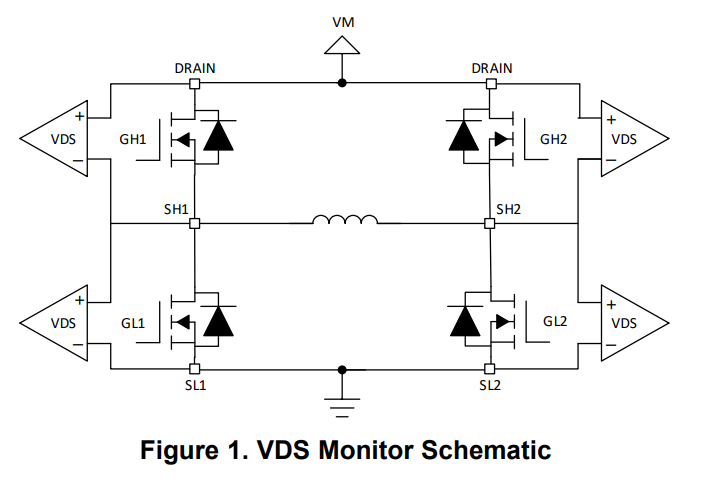
With TI motor gate drivers, designers can set VDS overcurrent protection threshold values based on the expected current through the FETs and failure conditions they are trying to protect against. This can be done many ways depending on the device used. For example, on DRV8705-Q1 it can be adjusted through VDS_LVL register settings for the SPI interface. For hardware interfaces, designers can set the desired threshold values by connecting resistors to the appropriate pin. Specifications for resistor values and threshold values vary from one device to another and can be found in each device’s datasheet.
In SPI devices, designers also have the option to set the OCP deglitch time. The duration of the overcurrent condition must be greater than the OCP deglitch time for an OCP condition to occur through the VDS register. OCP deglitch time preferences can vary depending on the time it takes to charge the FETs. The longer it takes to charge the FETs, the longer the OCP deglitch time is to ensure the FETs turn on and prevent false OCP conditions. For devices with a hardware interface, the OCP deglitch time falls within a range, specific to each device, which cannot be changed. In the event of an OCP condition, the FETs are disabled to prevent any damage. The specifics of a device’s response and recovery from an OCP condition vary from one to device to another
2 Using VDS Monitors to Identify Fault Types
Once the desired specifications for VDS monitoring are set, the device is ready to detect faults. Three reasons an OCP condition occurs is the H-bridge outputs (SHx) are either shorted to ground, shorted to the supply voltage, or shorted to each other. The type of short can be identified depending on which VDS monitor detects the OCP condition.
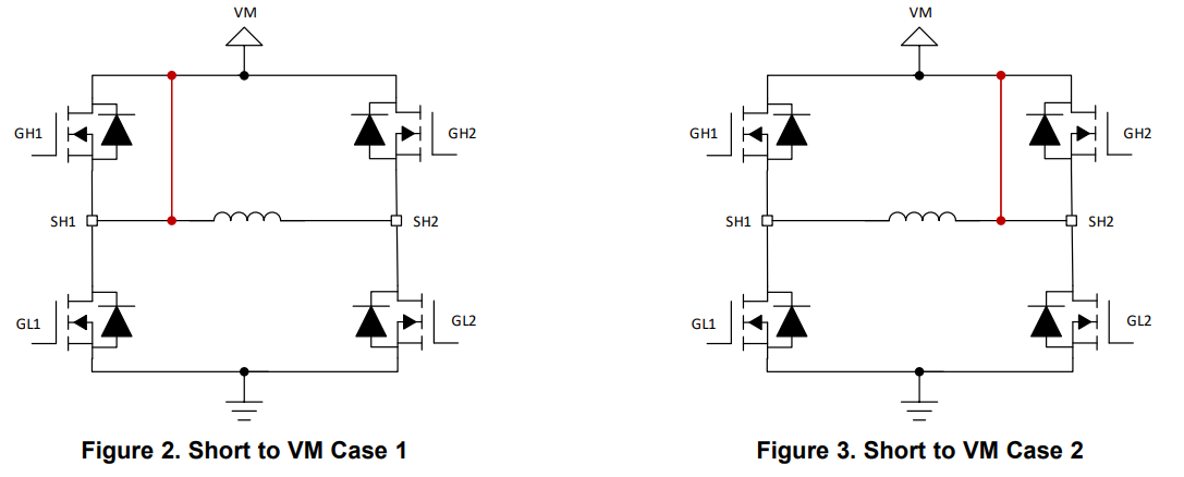
The short to supply scenario is shown in Figure 2 and Figure 3. In Short to VM Case 1, if the motor were to drive in reverse (only GH2 and GL1 are on) the voltage at SH1 would be VM and the VDS monitor across GL1 would trigger an OCP event. Similarly, in Short to VM Case 2, if the motor were to drive forward (only GH1 and GL2 are on) the VDS monitor across GL2 would detect an OCP condition. In low side brake (only GL1 and GL2 are on) the OCP condition is detected by whichever low side FET is on the same side as the short to supply.
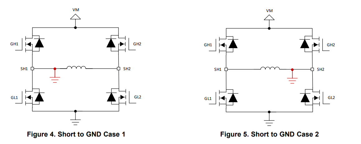
The Figure 4 and Figure 5 show the short to ground scenarios. If the motor were to drive forward (only GH1 and GL2 are on) in Short to GND Case 1, the high current through GH1 would trigger that FET’s VDS monitor for an OCP event. Similarly, if the motor were to drive in reverse (only GH2 and GL1 are on) in the Short to GND Case 2 scenario, GH2’s VDS monitor would trigger an OCP event.
Lastly, the SHx pins can be shorted to each other due to poor soldering, poor terminal connections, or a short in the motor windings. In this scenario, the VDS monitors across any driving FET will detect an OCP condition. For example, when driving forward (only GH1 and GL2 are on) the VDS monitors across FETs GH1 and GL2 will detect an OCP condition.
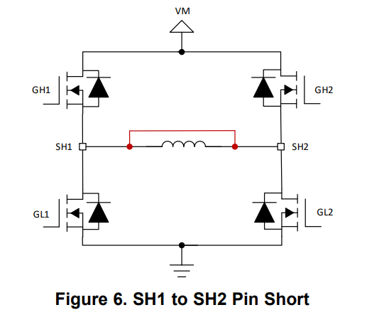
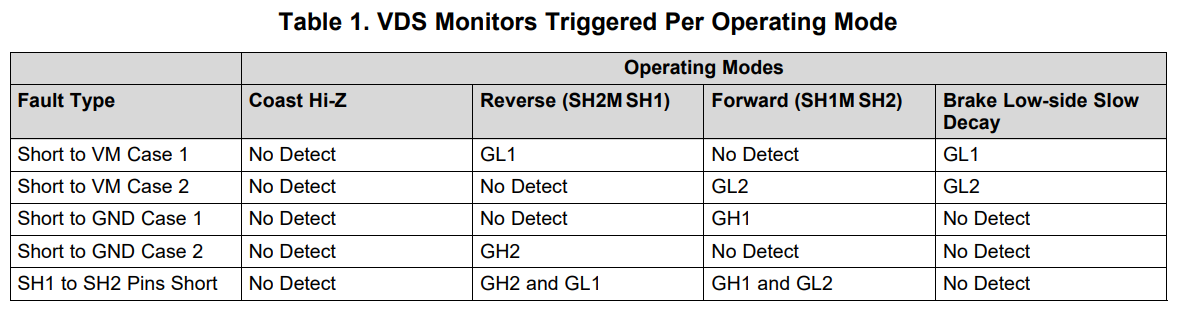
Table 1 provides a recap on which VDS monitors detect an OCP condition under the different fault scenarios for each operating mode.
3 Conclusion
Monitoring overcurrent conditions with VDS monitors is an easy to way detect what type of short circuit condition occurred. With a SPI interface, designers can quickly identify the location of the overcurrent condition and take action appropriately to prevent any system damage and draw conclusions on what type of overcurrent condition occurred.


 被折叠的 条评论
为什么被折叠?
被折叠的 条评论
为什么被折叠?
 到【灌水乐园】发言


