


 本文介绍了一种在Qt和OpenGLES环境下实现球体反射和折射效果的方法,包括球体绘制、立方体贴图的使用、菲涅尔效应的计算以及反射、折射向量的求解。
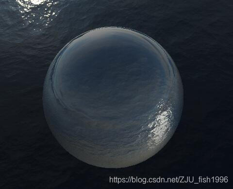
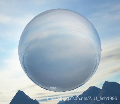
本次demo绘制了一个球体,包含了反射以及折射效果,两者通过菲涅尔公式进行混合。这篇文章主要是记录一下个人的实现细节,有一些细节的实现步骤还不是非常确定,还在查证中,所以此篇仅供参考。上面两图中折射取值不同。
框架:Qt 5.11, OpenGL ES 2.0
球体绘制
首先,为了更好的表现效果,此demo需要绘制一个球体。如果使用了glut框架,有现成的球体绘制函数,但是在原生的Qt中没有找到类似的函数,所以先花了时间做了球体绘制的计算。
本次计算使用了vertex buffer和index buffer。
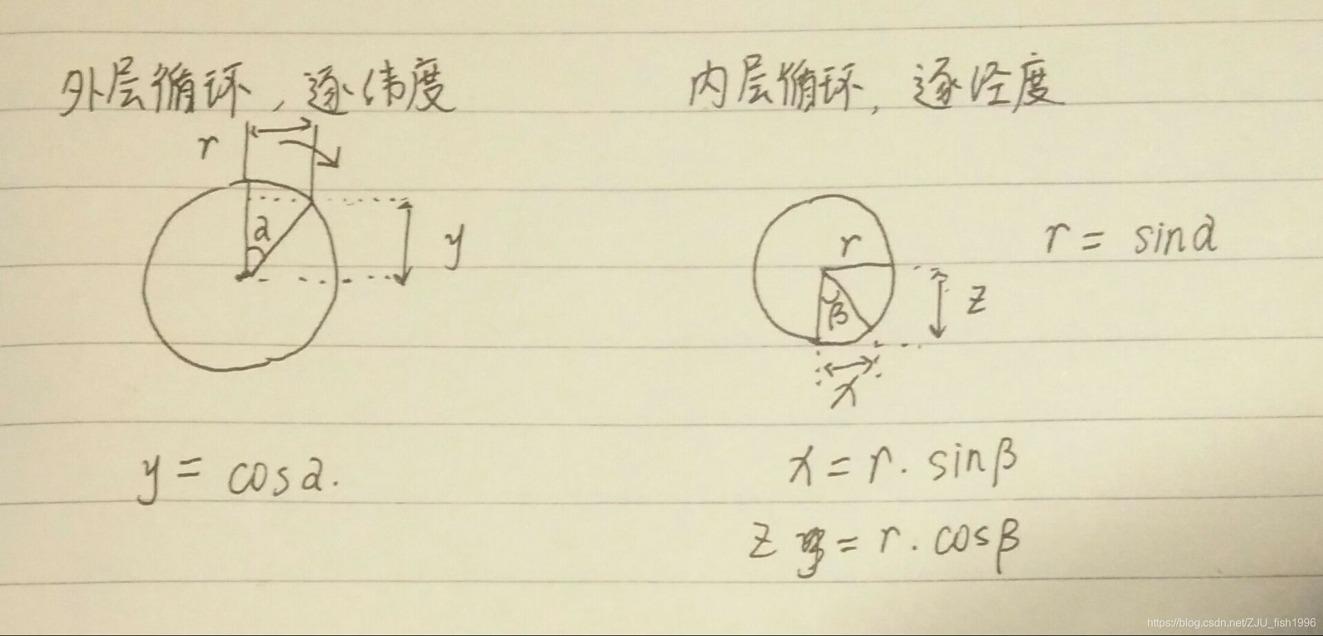
首先计算所有顶点。外层循环是从最高点沿着纬度变化的,左图的圆圈为沿着大球半径的纵切面,每次循环对应着一个a角,可由此计算出球的y坐标,即y = cos(a); 内层循环沿着经度变化的,右图的圆圈是沿着外层循环纬度处的横切面,它的半径可由a角求出,即 r = sin(a) ; 之后,可以对应求出该点处的x,z坐标分别为x = r * sin(b), z = r * cos(b)。
之后开始逐三角形记录顶点索引。
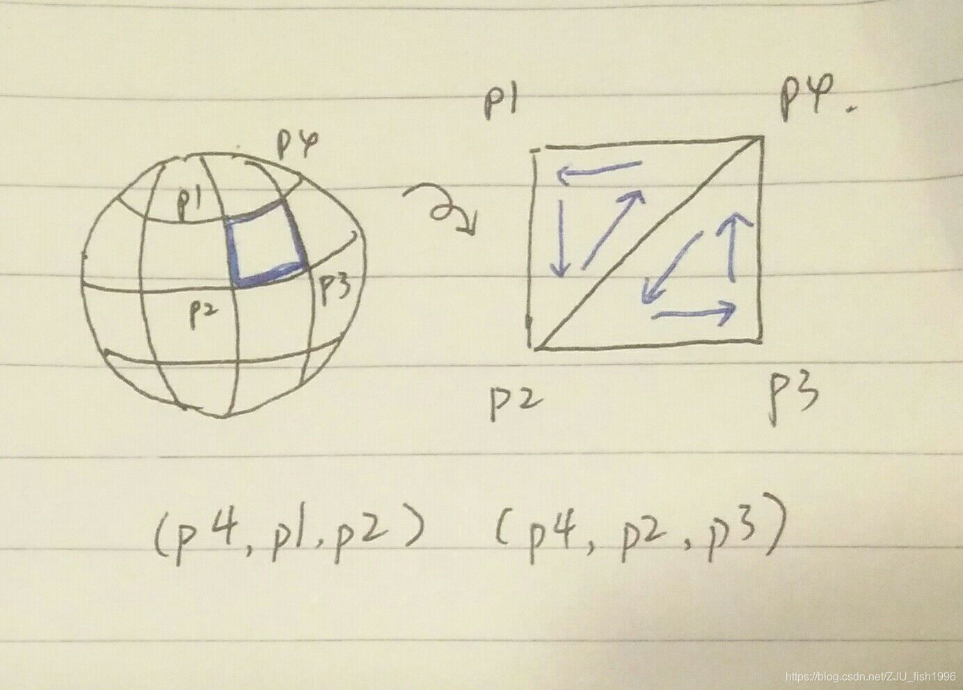
取上图的一个面片,求出对应的两个三角形,需要特别注意顺序要按照右手定则来取(四指沿着图中箭头走向,大拇指为法线方向),否则法线以及背面消隐都会是错误的。
struct VertexData2
{
    QVector3D position;
    QVector3D normal;
    int adjoinPlane = 0;
};

void GeometryEngine::initSphereGeometry()
{
    const int latitude = 40;
    const int longtitude = 40;
    const float PI = 3.14159f;
    QVector<VertexData2> Vertices;

    for(int i = 0;i <= latitude;i++) // 纬度
    {
        float y = cos(i * PI / latitude);
        for(int j = 0;j < longtitude; j++) // 经度
        {
            VertexData2 vertex;
            float x = sin(i * PI / latitude) * sin(2 * j * PI / longtitude);
            float z = sin(i * PI / latitude) * cos(2 * j * PI / longtitude);
            vertex.position = QVector3D(x,y,z);
            Vertices.push_back(vertex);
        }
    }

    QVector<GLushort> Indices;

    for(int i = 0;i < latitude;i++) // 纬度
    {
        for(int j = 0;j < longtitude; j++) // 经度
        {
            GLushort p1 = longtitude * i + j;
            GLushort p2 = longtitude * (i + 1) + j;
            GLushort p3 = longtitude * (i + 1) + j + 1;
            GLushort p4 = longtitude * i + j + 1;

            p1 = p1 % Vertices.size();
            p2 = p2 % Vertices.size();
            p3 = p3 % Vertices.size();
            p4 = p4 % Vertices.size();

            Indices.push_back(p4);
            Indices.push_back(p1);
            Indices.push_back(p2);

            Indices.push_back(p4);
            Indices.push_back(p2);
            Indices.push_back(p3);
        }
    }

    for(int i=0;i<Indices.size()/3;i++)
    {
        CalNormal(Vertices[Indices[3 * i]],Vertices[Indices[3 * i + 1]],Vertices[Indices[3 * i + 2]]);
    }
    sphereArrayBuf.bind();
    sphereArrayBuf.allocate(Vertices.data(), Vertices.size() * sizeof(VertexData2));

    sphereIndexBuf.bind();
    sphereIndexBuf.allocate(Indices.data(), Indices.size() * sizeof(GLushort));
}

void GeometryEngine::CalNormal(VertexData2& vertex0, VertexData2& vertex1, VertexData2& vertex2)
{
    QVector3D e0 = vertex1.position - vertex0.position;
    QVector3D e1 = vertex2.position - vertex0.position;

    QVector3D normal;
    normal = QVector3D::crossProduct(e0, e1);
    normal.normalize();

    QVector<VertexData2*> vertexArr = { &vertex0, &vertex1, &vertex2};
    for(int i = 0;i < vertexArr.size();i++)
    {
        vertexArr[i]->adjoinPlane++;
        float ratio = 1.0f / vertexArr[i]->adjoinPlane;
        vertexArr[i]->normal = vertexArr[i]->normal * (1 - ratio) + normal * ratio;
        vertexArr[i]->normal.normalize();
    }
}
立方体贴图(CubeMap)
为了能够让球体反射/折射环境,我们需要提供这样一个环境贴图。为了达到这一目的,我们可以使用OpenGL提供的立方体贴图。简单来说,立方体六个面上有着贴图,根据输入的向量,如下图方式发出该射线得到与立方体的交点,从而采样得到像素。
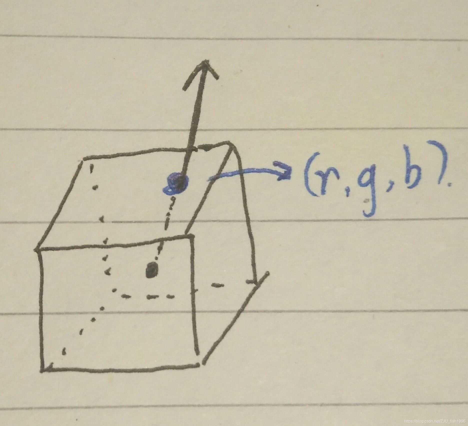
和普通纹理一样,我们首先需要生成这个纹理,区别是类型从GL_TEXTURE_2D变成了GL_TEXTURE_CUBE_MAP。
    glGenTextures(1, &m_nTextureId);
    glBindTexture(GL_TEXTURE_CUBE_MAP, m_nTextureId);
之后,我们按照右,左,顶,底,后 ,前的顺序准备六张贴图,调用glTexImage2D来指定cubemap的纹理,由于GL_TEXTURE_CUBE_MAP_POSITIVE_X以及之后的值是连续存储的,所以可以写成一个for循环。
由于QImage读出的数据是bgra格式,所以需要对数据做一点特殊处理,转换为rgb格式。
    QString path[] =
    {
        ":/right.jpg",":/left.jpg",":/top.jpg",":/bottom.jpg",
        ":/back.jpg",":/front.jpg",
    };
    for(int i = 0;i < 6;i++)
    {
        QImage image(path[i]);
        const int count = image.byteCount() / 4 * 3;
        unsigned char* data = new unsigned char[count];
        int cnt = 0;
        for(int j = 0;j < count / 3; j++)
        {
            data[3 * j] = image.bits()[cnt + 2];
            data[3 * j + 1] = image.bits()[cnt + 1];
            data[3 * j + 2] = image.bits()[cnt];
            cnt += 4;
        }
        glTexImage2D(GL_TEXTURE_CUBE_MAP_POSITIVE_X + i,
                     0,
                     GL_RGB,
                     image.width(),
                     image.height(),
                     0,
                     GL_RGB,
                     GL_UNSIGNED_BYTE,
                     data);
        delete[] data;
    }
最后,也和普通纹理类似,需要指定纹理环绕(采样坐标不在0~1之间)以及minmag(映射最终大小和原大小不一样)方式。
    glTexParameteri(GL_TEXTURE_CUBE_MAP, GL_TEXTURE_WRAP_S, GL_REPEAT);
    glTexParameteri(GL_TEXTURE_CUBE_MAP, GL_TEXTURE_WRAP_T, GL_REPEAT);
    glTexParameteri(GL_TEXTURE_CUBE_MAP, GL_TEXTURE_WRAP_R, GL_REPEAT);
    glTexParameteri(GL_TEXTURE_CUBE_MAP, GL_TEXTURE_MAG_FILTER, GL_NEAREST);
    glTexParameteri(GL_TEXTURE_CUBE_MAP, GL_TEXTURE_MIN_FILTER, GL_NEAREST);
反射效果
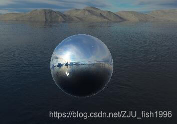
反射效果的只需要通过反射向量来采样立方体即可,在高光的计算中已经使用了反射向量,需要输入的是视线和法线位置。glsl已经有了内置的反射计算函数:
vec3 N = normalize(v_normal);
vec3 I = normalize(worldPos - cameraPos);
vec3 R = reflect(I, N);
vec4 reflectedColor = textureCube(cubemap, R);
折射效果
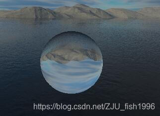
关于折射,使用折射参数0.66之后成像在球体里是反的,随着相机参数(改的是相机距离视点的位置参数)以及折射参数改变,图像可能变正,玻璃球本身有这么一个透镜的倒立成像属性,但是我不能确定是写错了还是事实如此,查了挺久资料~如果有人清楚求科普!
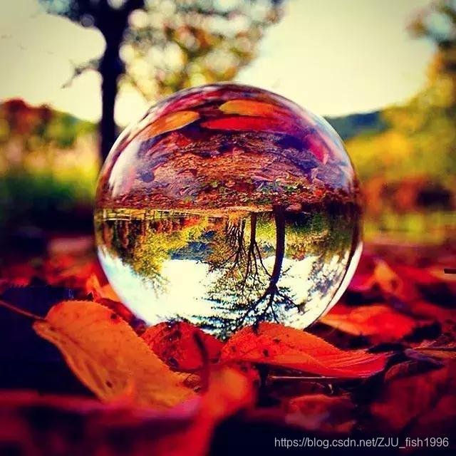
该图来自网络的摄影作品。
同样,类似于反射,折射是通过折射向量来采样立方体纹理的,glsl也为折射提供了内置函数。
    vec3 N = normalize(v_normal);
    vec3 I = normalize(worldPos - cameraPos);
    vec3 T = refract(I, N, 0.66);

    vec4 refractedColor = textureCube(cubemap, T);
菲涅尔效应
菲涅尔效应的直观表现就是,视线与表面法线越垂直,反射越弱,反之则越明显。
对于球体而言,中间部分以折射为主,看到的是对面的景象,有一种透明的效果;边缘部分以反射为主。下图中菲涅尔效应更为明显。
近似的计算公式: fresnel = base + scale * pow(1.0 - dot(I,N), indensity);
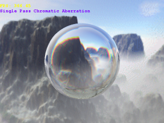
Qt内置的一个玻璃效果的着色器
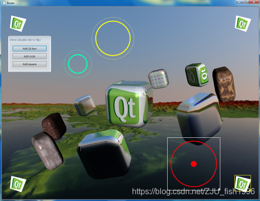
Qt的官方样例中,自带了一个玻璃的材质,思路同样也是折射 + 反射 + 菲涅尔效应混合。折射和反射是直接求解得到的,没有使用内置函数。不过大部分计算是在相机空间中完成的,之后再转到了世界空间。
varying vec3 position, normal;
varying vec4 specular, ambient, diffuse, lightDirection;

uniform sampler2D tex;
uniform samplerCube env;
uniform mat4 view;

// Some arbitrary values
// Arrays don't work here on glsl < 120, apparently.
//const float coeffs[6] = float[6](1.0/4.0, 1.0/4.1, 1.0/4.2, 1.0/4.3, 1.0/4.4, 1.0/4.5);
float coeffs(int i)
{
	return 1.0 / (3.0 + 0.1 * float(i));
}

void main()
{
    vec3 N = normalize(normal);
    vec3 I = -normalize(position);
    mat3 V = mat3(view[0].xyz, view[1].xyz, view[2].xyz);
    float IdotN = dot(I, N);
    float scales[6];
    vec3 C[6];
    for (int i = 0; i < 6; ++i) {
        scales[i] = (IdotN - sqrt(1.0 - coeffs(i) + coeffs(i) * (IdotN * IdotN)));
        C[i] = textureCube(env, (-I + coeffs(i) * N) * V).xyz;
    }
    vec4 refractedColor = 0.25 * vec4(C[5].x + 2.0*C[0].x + C[1].x, C[1].y + 2.0*C[2].y + C[3].y,
                          C[3].z + 2.0*C[4].z + C[5].z, 4.0);

    vec3 R = 2.0 * dot(-position, N) * N + position;
    vec4 reflectedColor = textureCube(env, R * V);

    gl_FragColor = mix(refractedColor, reflectedColor, 0.4 + 0.6 * pow(1.0 - IdotN, 2.0));
}
附录
vertex shader
#ifdef GL_ES
// Set default precision to medium
precision mediump int;
precision mediump float;
#endif

uniform mat4 ModelMatrix;
uniform mat4 IT_ModelMatrix;
uniform mat4 ViewMatrix;
uniform mat4 ProjectMatrix;

attribute vec4 a_position;
attribute vec3 a_normal;
attribute vec2 a_texcoord;

varying vec2 v_texcoord;
varying vec3 v_normal;
varying vec3 worldPos;

void main()
{
    gl_Position = ModelMatrix * a_position;
    worldPos = vec3(gl_Position);

    gl_Position = ViewMatrix * gl_Position;

    gl_Position = ProjectMatrix * gl_Position;

    v_texcoord = a_texcoord;

    mat3 M = mat3(IT_ModelMatrix[0].xyz, IT_ModelMatrix[1].xyz, IT_ModelMatrix[2].xyz);
    v_normal = M * a_normal;
}
fragment shader
#ifdef GL_ES
// Set default precision to medium
precision mediump int;
precision mediump float;
#endif
uniform samplerCube cubemap;
uniform mat4 ViewMatrix;
uniform int type;

uniform vec3 cameraPos;
varying vec3 worldPos;
varying vec3 v_normal;

float saturate(float data)
{
    if(data < 0.0)
    {
        return 0.0;
    }
    else if(data > 1.0)
    {
        return 1.0;
    }
    return data;
}

void main()
{
    vec3 N = normalize(v_normal);
    vec3 I = normalize(worldPos - cameraPos);
    vec3 R = reflect(I, N);

    vec4 reflectedColor = textureCube(cubemap, R);
    vec3 T = refract(I, N, 0.66);

    vec4 refractedColor = textureCube(cubemap, T);

    if(type == 0)
    {
        gl_FragColor = reflectedColor;
    }
    else if(type == 1)
    {
       gl_FragColor = refractedColor;
    }
    else if(type == 2)
    {
        float fresnel = 0.4 + 0.6 * pow(min(0.0, 1.0 - dot(-I, N)), 4.0);
        gl_FragColor = mix(refractedColor, reflectedColor, fresnel);
    }

}


 296
296

 被折叠的 条评论
为什么被折叠?
被折叠的 条评论
为什么被折叠?
 到【灌水乐园】发言


