


From:Blog
1. camera model
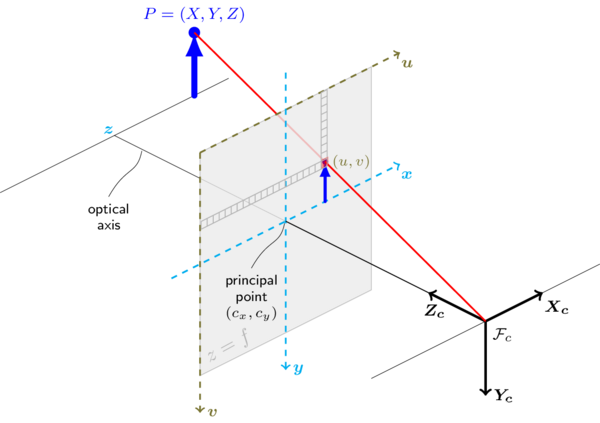
- X c Y c Z c X_cY_cZ_c XcYcZc : camera coordinate system
-
u
v
uv
uv: pixel coordinate system,
[dimension in pixel] -
x
y
xy
xy: image coordinate system,
[dimension in mm] -
X
Y
Z
XYZ
XYZ: word coordinate system,
[dimension in pixel]
2. X Y Z ⇒ X c Y c Z c XYZ \Rightarrow X_cY_cZ_c XYZ⇒XcYcZc
the main process is to transform points in word coordinate system
X
Y
Z
XYZ
XYZ into camera coordinate system
X
c
Y
c
Z
c
X_cY_cZ_c
XcYcZc, this process is done with a rotation and shift matrix
[
x
c
y
c
z
c
1
]
=
[
R
T
0
1
]
[
x
w
y
w
x
w
1
]
\begin{bmatrix} x_c \\ y_c \\ z_c \\ 1 \end{bmatrix} =\begin{bmatrix} R & T \\ 0 & 1 \\ \end{bmatrix} \begin{bmatrix} x_w \\ y_w \\ x_w \\ 1 \end{bmatrix}
⎣⎢⎢⎡xcyczc1⎦⎥⎥⎤=[R0T1]⎣⎢⎢⎡xwywxw1⎦⎥⎥⎤
where
R
R
R is the rotation matrix
R
=
[
r
11
r
12
r
13
r
21
r
22
r
23
r
31
r
32
r
33
]
R=\begin{bmatrix} r_{11} & r_{12} & r_{13} \\ r_{21} & r_{22} & r_{23} \\ r_{31} & r_{32} & r_{33} \end{bmatrix}
R=⎣⎡r11r21r31r12r22r32r13r23r33⎦⎤
and
T
T
T is the shift vector
T
=
[
t
x
t
y
t
z
]
T
T=\begin{bmatrix} t_x & t_y & t_z \end{bmatrix} ^T
T=[txtytz]T
3. X c Y c Z c ⇒ x y X_cY_cZ_c \Rightarrow xy XcYcZc⇒xy
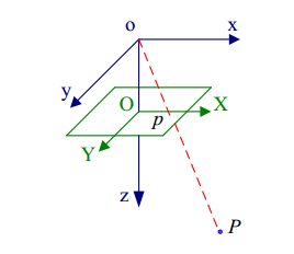
After transformed in camera coordinate system, we can project the points into the image plane using pinhole model. suppose the point
p
c
=
(
x
c
,
y
c
,
z
c
)
T
p_c=(x_c, y_c, z_c)^T
pc=(xc,yc,zc)T in camera coordinate system, then it’s coordinate in image plane can be obtained as the follow:
x
x
w
=
y
y
w
=
f
z
w
\frac{x}{x_w} = \frac{y}{y_w} = \frac{f}{z_w}
xwx=ywy=zwf
so
{
x
=
f
x
c
z
c
y
=
f
y
c
z
c
\left\{ \begin{aligned} x & = \frac{fx_c}{z_c} \\ y & = \frac{fy_c}{z_c} \end{aligned} \right.
⎩⎪⎪⎨⎪⎪⎧xy=zcfxc=zcfyc
thus
z
c
[
x
y
1
]
=
[
f
0
0
0
0
f
0
0
0
0
1
0
]
[
x
c
y
c
z
c
1
]
z_c\begin{bmatrix} x \\ y \\ 1 \end{bmatrix} =\begin{bmatrix} f & 0 & 0 & 0\\ 0 & f & 0 & 0\\ 0 & 0 & 1 & 0\\ \end{bmatrix} \begin{bmatrix} x_c \\ y_c \\ z_c \\ 1 \end{bmatrix}
zc⎣⎡xy1⎦⎤=⎣⎡f000f0001000⎦⎤⎣⎢⎢⎡xcyczc1⎦⎥⎥⎤
4. x y ⇒ u v xy \Rightarrow uv xy⇒uv
4.1 condition: u ⊥ v u \perp v u⊥v
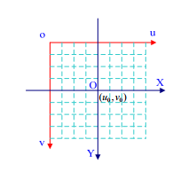
usually, the origin point of pixel coordinate system is located in the top left corner while the origin of image coordinate system is located in the center of the image plane, causing a shift vector ( u 0 , v 0 ) (u_0,v_0) (u0,v0) between this two coordinate system.
Denoted the size of each pixel in
u
,
v
u,v
u,v direction as
d
x
,
d
y
dx,dy
dx,dy (dimension in mm). then we can get the relationship between them.
[
u
v
1
]
=
[
1
d
x
0
u
0
0
1
d
y
v
0
0
0
1
]
[
x
y
1
]
\begin{bmatrix} u \\ v \\ 1 \end{bmatrix} =\begin{bmatrix} \frac{1}{dx} & 0 & u_0 \\ 0 & \frac{1}{dy} & v_0 \\ 0 & 0 & 1 \\ \end{bmatrix} \begin{bmatrix} x \\ y \\ 1 \end{bmatrix}
⎣⎡uv1⎦⎤=⎣⎡dx1000dy10u0v01⎦⎤⎣⎡xy1⎦⎤
4.2 condition: u ⊥̸ v u \not{\perp} v u⊥v
In this condition, the matrix is a little complex but still easy to understand
{
u
=
x
−
y
c
o
t
θ
d
x
+
u
0
v
=
y
d
y
s
i
n
θ
+
v
0
\left\{ \begin{aligned} u & = \frac{x-ycot\theta}{dx}+u_0 \\ v & = \frac{y}{dysin\theta}+v_0 \end{aligned} \right.
⎩⎪⎨⎪⎧uv=dxx−ycotθ+u0=dysinθy+v0
thus
[
u
v
1
]
=
[
1
d
x
−
1
d
x
t
a
n
θ
u
0
0
1
d
y
s
i
n
θ
v
0
0
0
1
]
[
x
y
1
]
=
[
α
x
c
u
0
0
α
y
v
0
0
0
1
]
[
x
y
1
]
\begin{aligned} \begin{bmatrix} u \\ v \\ 1 \end{bmatrix} & =\begin{bmatrix} \frac{1}{dx} & -\frac{1}{d_xtan\theta} & u_0 \\ 0 & \frac{1}{dysin\theta} & v_0 \\ 0 & 0 & 1 \\ \end{bmatrix} \begin{bmatrix} x \\ y \\ 1 \end{bmatrix} \\ & =\begin{bmatrix} \alpha_x & c & u_0 \\ 0 & \alpha_y & v_0 \\ 0 & 0 & 1 \\ \end{bmatrix} \begin{bmatrix} x \\ y \\ 1 \end{bmatrix} \end{aligned}
⎣⎡uv1⎦⎤=⎣⎡dx100−dxtanθ1dysinθ10u0v01⎦⎤⎣⎡xy1⎦⎤=⎣⎡αx00cαy0u0v01⎦⎤⎣⎡xy1⎦⎤
5. relation
Through the analysis of above, the relationship between world and pixel coordinate system can be written as follows:
z
c
[
u
v
1
]
=
[
α
x
c
u
0
0
0
α
y
v
0
0
0
0
1
]
[
f
0
0
0
0
f
0
0
0
0
1
0
]
[
R
T
0
1
]
[
x
w
y
w
x
w
1
]
=
[
α
x
c
u
0
0
0
α
y
v
0
0
0
0
1
0
]
[
R
T
0
1
]
[
x
w
y
w
x
w
1
]
=
M
1
M
2
X
w
=
M
X
w
\begin{aligned} z_c\begin{bmatrix} u \\ v \\ 1 \end{bmatrix} & =\begin{bmatrix} \alpha_x & c & u_0 & 0 \\ 0 & \alpha_y & v_0 & 0 \\ 0 & 0 & 1 \\ \end{bmatrix} \begin{bmatrix} f & 0 & 0 & 0\\ 0 & f & 0 & 0\\ 0 & 0 & 1 & 0\\ \end{bmatrix} \begin{bmatrix} R & T \\ 0 & 1 \\ \end{bmatrix} \begin{bmatrix} x_w \\ y_w \\ x_w \\ 1 \end{bmatrix} \\ & =\begin{bmatrix} \alpha_x & c & u_0 & 0 \\ 0 & \alpha_y & v_0 & 0 \\ 0 & 0 & 1 & 0 \end{bmatrix} \begin{bmatrix} R & T \\ 0 & 1 \\ \end{bmatrix} \begin{bmatrix} x_w \\ y_w \\ x_w \\ 1 \end{bmatrix} \\ & =M_1M_2X_w \\ & = MX_w \end{aligned}
zc⎣⎡uv1⎦⎤=⎣⎡αx00cαy0u0v0100⎦⎤⎣⎡f000f0001000⎦⎤[R0T1]⎣⎢⎢⎡xwywxw1⎦⎥⎥⎤=⎣⎡αx00cαy0u0v01000⎦⎤[R0T1]⎣⎢⎢⎡xwywxw1⎦⎥⎥⎤=M1M2Xw=MXw
where
α
x
=
f
/
d
x
\alpha_x=f/dx
αx=f/dx and
α
y
=
f
/
d
y
\alpha_y=f/dy
αy=f/dy is called scale factors in image
u
u
u and
v
v
v axes,
M
1
M_1
M1 is called camera intrinsic matrix,
M
2
M_2
M2 is called camera extrinsic parameters,c is the parameter describing the skewness of the two image axes.
6. Camera Calibration
6.1. general conception
The method is proposed by Zhengyou Zhang which only require a camera to observe a planar patttern at a few (at least two) different orientations.
In order to keep equations consistent with the paper written by Zhengyou Zhang, here the transformation matrix is rewritten as the follow.
s
m
~
=
A
[
R
t
]
M
~
s\widetilde{m}=A\begin{bmatrix}R & t\end{bmatrix}\widetilde{M}
sm
=A[Rt]M
where
m
~
=
[
u
,
v
,
1
]
T
\widetilde{m}=\begin{bmatrix}u,v,1\end{bmatrix}^T
m
=[u,v,1]T represent the 2D point and
M
~
=
[
X
,
Y
,
Z
,
1
]
T
\widetilde{M}=\begin{bmatrix}X,Y, Z,1\end{bmatrix}^T
M
=[X,Y,Z,1]T represent the corresponding 3D point and
A
=
[
α
c
u
0
0
β
v
0
0
0
1
]
A=\begin{bmatrix} \alpha & c & u_0 \\ 0 & \beta &v_0 \\ 0 & 0 & 1 \end{bmatrix}
A=⎣⎡α00cβ0u0v01⎦⎤
To calibrate the camera, the model plane was assumed to be
Z
=
0
Z=0
Z=0, then
s
[
u
v
1
]
=
A
[
r
1
r
2
r
3
t
]
[
X
Y
0
1
]
=
A
[
r
1
r
2
t
]
[
X
Y
1
]
s \begin{bmatrix} u \\ v \\ 1 \end{bmatrix} =A\begin{bmatrix} r_1 & r_2 & r_3 & t \end{bmatrix} \begin{bmatrix} X \\ Y \\ 0 \\ 1 \end{bmatrix} =A\begin{bmatrix} r_1 & r_2 & t \end{bmatrix} \begin{bmatrix} X \\ Y \\ 1 \end{bmatrix}
s⎣⎡uv1⎦⎤=A[r1r2r3t]⎣⎢⎢⎡XY01⎦⎥⎥⎤=A[r1r2t]⎣⎡XY1⎦⎤
according to the above equation,
M
~
=
[
X
,
Y
,
1
]
T
\widetilde{M}=\begin{bmatrix}X,Y,1\end{bmatrix}^T
M
=[X,Y,1]T is defined in the following part. therefore, the homography matrix
H
H
H is induced.
s
m
~
=
H
M
~
s\widetilde{m}=H\widetilde{M}
sm
=HM
where
H
=
A
[
r
1
r
2
t
]
H=A\begin{bmatrix}r_1 & r_2 & t\end{bmatrix}
H=A[r1r2t]
6.2. Estimation of the homography matrix H H H
M
i
M_i
Mi and
m
i
m_i
mi respectively represent the model and image points. According to maximum likelihood method, the object function should be minimized.
∑
i
(
m
i
−
m
i
^
)
T
Λ
−
1
(
m
i
−
m
i
^
)
\sum_i(m_i-\hat{m_i})^T\Lambda^{-1}(m_i-\hat{m_i})
i∑(mi−mi^)TΛ−1(mi−mi^)
where
m
i
^
=
1
h
3
ˉ
M
i
[
h
1
ˉ
M
i
h
2
ˉ
M
i
]
\hat{m_i}=\frac{1}{\bar{h_3}M_i}\begin{bmatrix} \bar{h_1}M_i \\ \bar{h_2}M_i \end{bmatrix}
mi^=h3ˉMi1[h1ˉMih2ˉMi]
h
i
ˉ
\bar{h_i}
hiˉ is the
i
t
h
i^{th}
ith row of H, assuming
Λ
m
i
=
σ
2
I
\Lambda_{m_i}=\sigma^2I
Λmi=σ2I for all
i
i
i, thus,
∑
i
∣
∣
m
i
−
m
i
^
∣
∣
2
\sum\limits_i||m_i-\hat{m_i}||^2
i∑∣∣mi−mi^∣∣2 should be minimized. The Levenberg-Marquardt algorithm was implemented and initial guess can be obtained as follows:
Let
x
=
[
h
1
T
ˉ
,
h
2
T
ˉ
,
h
3
T
ˉ
]
T
x=[\bar{h_1^T},\bar{h_2^T},\bar{h_3^T}]^T
x=[h1Tˉ,h2Tˉ,h3Tˉ]T. then
s
m
~
=
H
M
~
s\widetilde{m}=H\widetilde{M}
sm
=HM
can be rewritten as
[
M
~
T
0
T
−
u
M
~
T
0
T
M
~
T
−
v
M
~
T
]
x
=
0
\begin{bmatrix} \widetilde{M}^T & 0^T & -u\widetilde{M}^T \\ 0^T & \widetilde{M}^T & -v\widetilde{M}^T \end{bmatrix} x=0
[M
T0T0TM
T−uM
T−vM
T]x=0
for example
s
[
u
i
v
i
1
]
=
[
h
11
h
12
h
13
h
21
h
22
h
23
h
31
h
32
h
33
]
[
x
w
i
y
w
i
1
]
s \begin{bmatrix} u_i \\ v_i \\ 1 \end{bmatrix} =\begin{bmatrix} h_{11} & h_{12} & h_{13} \\ h_{21} & h_{22} & h_{23} \\ h_{31} & h_{32} & h_{33} \end{bmatrix} \begin{bmatrix} x_{wi} \\ y_{wi} \\ 1 \end{bmatrix}
s⎣⎡uivi1⎦⎤=⎣⎡h11h21h31h12h22h32h13h23h33⎦⎤⎣⎡xwiywi1⎦⎤
that is
{
h
11
x
w
i
+
h
12
y
w
i
+
h
13
−
h
31
x
w
i
u
i
−
h
32
y
w
i
u
i
−
h
33
u
i
=
0
h
21
x
w
i
+
h
22
y
w
i
+
h
23
−
h
31
x
w
i
v
i
−
h
32
y
w
i
v
i
−
h
33
v
i
=
0
\begin{cases} h_{11}x_{wi}+h_{12}y_{wi}+h_{13}-h_{31}x_{wi}u_i-h_{32}y_{wi}u_i-h_{33}u_i & = 0 \\ h_{21}x_{wi}+h_{22}y_{wi}+h_{23}-h_{31}x_{wi}v_i-h_{32}y_{wi}v_i-h_{33}v_i & = 0 \end{cases}
{h11xwi+h12ywi+h13−h31xwiui−h32ywiui−h33uih21xwi+h22ywi+h23−h31xwivi−h32ywivi−h33vi=0=0
assuming
h
33
=
1
h_{33}=1
h33=1, because there is no impact on the matrix
H
H
H, this assumes just scale the matrix
H
H
H. so we have
[
x
w
i
y
w
i
1
0
0
0
−
u
i
x
w
i
−
u
i
y
w
i
−
u
i
0
0
0
x
w
i
y
w
i
1
−
v
i
x
w
i
−
v
i
y
w
i
−
v
i
]
[
h
11
h
12
h
13
h
21
h
22
h
23
h
31
h
32
1
]
=
0
\begin{bmatrix} x_{wi} & y_{wi} & 1 & 0 & 0 & 0 & -u_ix_{wi} & -u_iy_{wi} & -u_i \\ 0 & 0 & 0 & x_{wi} & y_{wi} & 1 & -v_ix_{wi} & -v_iy_{wi} & -v_i \end{bmatrix} \begin{bmatrix} h_{11} \\ h_{12} \\ h_{13} \\ h_{21} \\ h_{22} \\ h_{23} \\ h_{31} \\ h_{32} \\ 1 \\ \end{bmatrix}=0
[xwi0ywi0100xwi0ywi01−uixwi−vixwi−uiywi−viywi−ui−vi]⎣⎢⎢⎢⎢⎢⎢⎢⎢⎢⎢⎢⎢⎡h11h12h13h21h22h23h31h321⎦⎥⎥⎥⎥⎥⎥⎥⎥⎥⎥⎥⎥⎤=0
simply, we have
L
x
=
0
Lx=0
Lx=0, where
L
L
L is a
2
n
×
9
2n\times9
2n×9 matrix. for this equation, SVD method can be used or the eigenvector of
L
T
L
L^TL
LTL can be estimated for this equation. Note that there is one homography matrix for each image and they are different from each other. Since there are 8 unknown parameters, in each image, 4 corresponding points are needed to estimate matrix
H
H
H.
6.3. constraints of intrinsic parameters
denote H as
H
=
[
h
1
h
2
h
3
]
H=\begin{bmatrix}h1 & h_2 & h_3\end{bmatrix}
H=[h1h2h3], then
[
h
1
h
2
h
3
]
=
λ
A
[
r
1
r
2
r
3
]
\begin{bmatrix}h1 & h_2 & h_3\end{bmatrix}=\lambda A\begin{bmatrix}r1 & r_2 & r_3\end{bmatrix}
[h1h2h3]=λA[r1r2r3]
because
r
1
r_1
r1 and
r
2
r_2
r2 are orthonormal, we have
h
1
T
A
−
T
A
−
1
h
2
=
0
h
1
T
A
−
T
A
−
1
h
1
=
h
2
T
A
−
T
A
−
1
h
2
\begin{aligned} h_1^TA^{-T}A^{-1}h_2 & = 0 \\ h_1^TA^{-T}A^{-1}h_1 & = h_2^TA^{-T}A^{-1}h_2 \end{aligned}
h1TA−TA−1h2h1TA−TA−1h1=0=h2TA−TA−1h2
note that there are 8 parameters (3 for rotation, 3 for translation and 2 for intrinsic parameters)
Let
B
=
A
−
T
A
−
1
=
[
B
11
B
12
B
13
B
21
B
22
B
23
B
31
B
32
B
33
]
=
[
1
α
x
2
−
c
α
x
2
α
y
c
v
0
−
u
0
α
y
α
x
2
α
y
−
c
α
x
2
α
y
c
2
α
x
2
α
y
2
+
1
α
y
2
−
c
(
c
v
0
−
u
0
α
y
)
α
x
2
α
y
2
−
v
0
α
y
2
c
v
0
−
u
0
α
y
α
x
2
α
y
−
c
(
c
v
0
−
u
0
α
y
)
α
x
2
α
y
2
−
v
0
α
y
2
(
c
v
0
−
u
0
α
y
)
2
α
x
2
α
y
2
+
v
0
2
α
y
2
+
1
]
\begin{aligned} B & =A^{-T}A^{-1}=\begin{bmatrix} B_{11} & B_{12} & B_{13} \\ B_{21} & B_{22} & B_{23} \\ B_{31} & B_{32} & B_{33} \\ \end{bmatrix} \\ & = \begin{bmatrix} \frac{1}{\alpha_x^2} & -\frac{c}{\alpha_x^2\alpha_y} & \frac{cv_0-u_0\alpha_y}{\alpha_x^2\alpha_y} \\ -\frac{c}{\alpha_x^2\alpha_y} & \frac{c^2}{\alpha_x^2\alpha_y^2}+\frac{1}{\alpha_y^2} & -\frac{c(cv_0-u_0\alpha_y)}{\alpha_x^2\alpha_y^2}-\frac{v_0}{\alpha_y^2} \\ \frac{cv_0-u_0\alpha_y}{\alpha_x^2\alpha_y} & -\frac{c(cv_0-u_0\alpha_y)}{\alpha_x^2\alpha_y^2}-\frac{v_0}{\alpha_y^2} & \frac{(cv_0-u_0\alpha_y)^2}{\alpha_x^2\alpha_y^2}+\frac{v_0^2}{\alpha_y^2}+1 \\ \end{bmatrix} \end{aligned}
B=A−TA−1=⎣⎡B11B21B31B12B22B32B13B23B33⎦⎤=⎣⎢⎢⎡αx21−αx2αycαx2αycv0−u0αy−αx2αycαx2αy2c2+αy21−αx2αy2c(cv0−u0αy)−αy2v0αx2αycv0−u0αy−αx2αy2c(cv0−u0αy)−αy2v0αx2αy2(cv0−u0αy)2+αy2v02+1⎦⎥⎥⎤
now, define
b
=
[
B
11
B
12
B
22
B
13
B
23
B
33
]
b=\begin{bmatrix} B_{11} & B_{12} & B_{22} & B_{13} & B_{23} & B_{33}\\ \end{bmatrix}
b=[B11B12B22B13B23B33]
and let the
i
t
h
i^{th}
ith column vector of
H
H
H be
h
i
=
[
h
i
1
,
h
i
2
,
h
i
3
]
T
h_i=\begin{bmatrix}h_{i1},h_{i2},h_{i3}\end{bmatrix}^T
hi=[hi1,hi2,hi3]T, then
h
i
T
B
h
j
=
v
i
j
T
b
h_i^TBh_j=v_{ij}^Tb
hiTBhj=vijTb
where
v
i
j
=
[
h
i
1
h
j
1
,
h
i
1
h
j
2
+
h
i
2
h
j
1
,
h
i
2
h
j
2
,
h
i
3
h
j
1
+
h
i
1
h
j
3
,
h
i
3
h
j
2
+
h
i
2
h
j
3
,
h
i
3
h
j
3
]
v_{ij}=\begin{bmatrix} h_{i1}h_{j1},h_{i1}h_{j2}+h_{i2}h_{j1},h_{i2}h_{j2},h_{i3}h_{j1}+h_{i1}h_{j3},h_{i3}h_{j2}+h_{i2}h_{j3},h_{i3}h_{j3} \end{bmatrix}
vij=[hi1hj1,hi1hj2+hi2hj1,hi2hj2,hi3hj1+hi1hj3,hi3hj2+hi2hj3,hi3hj3]
therefore
[
v
12
T
(
v
11
−
v
22
)
T
]
b
=
0
\begin{bmatrix} v_{12}^T \\ (v_{11}-v_{22})^T \end{bmatrix} b=0
[v12T(v11−v22)T]b=0
if n images of the model plane are observed, we have
V
b
=
0
Vb=0
Vb=0
where
V
V
V is a
2
n
×
6
2n \times 6
2n×6 matrix.
if
n
≥
3
n \geq 3
n≥3, unique value of b will be obtained, if
n
=
3
n = 3
n=3, additional constraint
c
=
0
c=0
c=0 can be added to solve the equations. once
b
b
b is estimated, we can compute the camera intrinsic matrix
A
A
A as follows
v
0
=
(
B
12
B
13
−
B
11
B
23
)
/
(
B
11
B
22
−
B
12
2
)
λ
=
B
33
−
[
B
13
2
+
v
0
(
B
12
B
13
−
B
11
B
23
)
]
/
B
11
α
=
λ
/
B
11
β
=
λ
B
11
/
(
B
11
B
22
−
B
12
2
)
c
=
−
B
12
α
2
β
/
λ
u
0
=
c
v
0
/
α
−
B
13
α
2
/
λ
\begin{aligned} v_0 & = (B_{12}B_{13}-B_{11}B_{23})/(B_{11}B_{22}-B_{12}^2) \\ \lambda & = B_{33}-[B_{13}^2+v_0(B_{12}B_{13}-B_{11}B_{23})]/B_{11} \\ \alpha & = \sqrt{\lambda/B_{11}} \\ \beta & = \sqrt{\lambda B_{11}/(B_{11}B_{22}-B_{12}^2)} \\ c & = -B_{12}\alpha^2\beta/\lambda \\ u_0 & = cv_0/\alpha-B_{13}\alpha^2/\lambda \end{aligned}
v0λαβcu0=(B12B13−B11B23)/(B11B22−B122)=B33−[B132+v0(B12B13−B11B23)]/B11=λ/B11=λB11/(B11B22−B122)=−B12α2β/λ=cv0/α−B13α2/λ
6.4 Distortion model
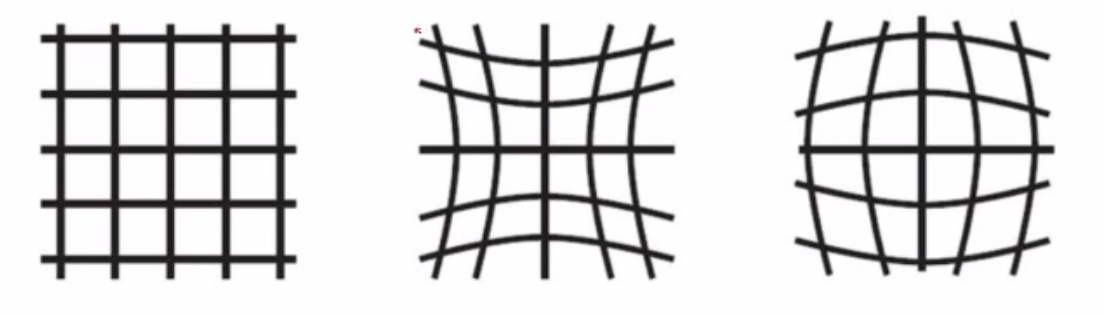
Only the first two terms of radial distortion are considered. Let
(
u
,
v
)
(u,v)
(u,v) be the ideal (no distorted) pixel image coordinates, and
(
u
˘
,
v
˘
)
(\breve{u},\breve{v})
(u˘,v˘) the corresponding real observed image coordinates. similarly,
(
x
,
y
)
(x,y)
(x,y) and
(
x
˘
,
y
˘
)
(\breve{x},\breve{y})
(x˘,y˘) are the same meaning. So
x
˘
=
x
+
x
[
k
1
(
x
2
+
y
2
)
+
k
2
(
x
2
+
y
2
)
2
]
y
˘
=
y
+
y
[
k
1
(
x
2
+
y
2
)
+
k
2
(
x
2
+
y
2
)
2
]
\begin{aligned} \breve{x} & = x + x[k_1(x^2+y^2)+k_2(x^2+y^2)^2] \\ \breve{y} & = y + y[k_1(x^2+y^2)+k_2(x^2+y^2)^2] \end{aligned}
x˘y˘=x+x[k1(x2+y2)+k2(x2+y2)2]=y+y[k1(x2+y2)+k2(x2+y2)2]
where
k
1
k_1
k1 and
k
2
k_2
k2 are the coefficients of the radial distortion. thus we have
u
˘
=
u
+
(
u
−
u
0
)
[
k
1
(
x
2
+
y
2
)
+
k
2
(
x
2
+
y
2
)
2
]
v
˘
=
v
+
(
v
−
v
0
)
[
k
1
(
x
2
+
y
2
)
+
k
2
(
x
2
+
y
2
)
2
]
\begin{aligned} \breve{u} & = u + (u-u_0)[k_1(x^2+y^2)+k_2(x^2+y^2)^2] \\ \breve{v} & = v + (v-v_0)[k_1(x^2+y^2)+k_2(x^2+y^2)^2] \end{aligned}
u˘v˘=u+(u−u0)[k1(x2+y2)+k2(x2+y2)2]=v+(v−v0)[k1(x2+y2)+k2(x2+y2)2]
because the distortion is small, we would like to estimate the other parameters followed by estimating
k
1
k_1
k1 and
k
2
k_2
k2
[
(
u
−
u
0
)
(
x
2
+
y
2
)
(
u
−
u
0
)
(
x
2
+
y
2
)
2
(
v
−
v
0
)
(
x
2
+
y
2
)
(
v
−
v
0
)
(
x
2
+
y
2
)
2
]
[
k
1
k
2
]
=
[
u
˘
−
u
v
˘
−
v
]
\begin{bmatrix} (u-u_0)(x^2+y^2) & (u-u_0)(x^2+y^2)^2 \\ (v-v_0)(x^2+y^2) & (v-v_0)(x^2+y^2)^2 \end{bmatrix} \begin{bmatrix} k_1 \\ k_2 \end{bmatrix} =\begin{bmatrix} \breve{u}-u \\ \breve{v}-v \end{bmatrix}
[(u−u0)(x2+y2)(v−v0)(x2+y2)(u−u0)(x2+y2)2(v−v0)(x2+y2)2][k1k2]=[u˘−uv˘−v]
Given
m
m
m points in
n
n
n images, we have
2
m
n
2mn
2mn equations and the matrix
D
k
=
d
Dk=d
Dk=d, where
k
=
[
k
1
,
k
2
]
T
k=[k_1,k_2]^T
k=[k1,k2]T, and the solution is given by
k
=
(
D
T
D
)
−
1
D
T
d
k=(D^TD)^{-1}D^Td
k=(DTD)−1DTd
6.5 Complete Maximum Likelihood Estimation
∑ i = 1 n ∑ j = 1 m ∣ ∣ m i , j − m ˘ ( A , k 1 , k 2 , R i , t i , M j ) ∣ ∣ 2 \sum\limits_{i=1}^n\sum\limits_{j=1}^m||m_{i,j}-\breve{m}(A,k_1,k_2,R_i,t_i,M_j)||^2 i=1∑nj=1∑m∣∣mi,j−m˘(A,k1,k2,Ri,ti,Mj)∣∣2
the initial guess of A A A and { R i , t i ∣ i = 1 , . . n } \{R_i,t_i|i=1,..n\} {Ri,ti∣i=1,..n} can be estimated in Sec 6.2 and Sec 6.3. An initial guess of { k i ∣ i = 1 , 2 } \{k_i|i=1,2\} {ki∣i=1,2} can be obtained in Sec 6.4 or simply set them to zero. the Levevberg-Marquartdt Algorithm is implemented here to solve the nonlinear problem.
Reference
[1] Zhang Z . Flexible camera calibration by viewing a plane from unknown orientation[C]// Computer Vision, 1999. The Proceedings of the Seventh IEEE International Conference on. IEEE Computer Society, 1999.
[2] blog: https://www.cnblogs.com/zyly/p/9366080.html
[3] blog: https://blog.youkuaiyun.com/lql0716/article/details/71973318?locationNum=8&fps=1
 6615


 扫一扫


 被折叠的 条评论
为什么被折叠?
 到【灌水乐园】发言


