


💥💥💞💞欢迎来到本博客❤️❤️💥💥
🏆博主优势:🌞🌞🌞博客内容尽量做到思维缜密,逻辑清晰,为了方便读者。
⛳️座右铭:行百里者,半于九十。
📋📋📋本文目录如下:🎁🎁🎁
目录
💥1 概述
一、引言
在智能交通系统、自动驾驶等领域,准确的车辆跟踪至关重要。卡尔曼滤波器作为一种高效的状态估计工具,能够在存在噪声的情况下,对动态系统的状态进行最优估计。本项目旨在利用卡尔曼滤波器实现对车辆的跟踪,并借助仿真的 RADAR 数据进行测量更新,以提高跟踪的准确性和可靠性。
二、卡尔曼滤波器原理
卡尔曼滤波器基于状态空间模型,通过预测和更新两个步骤来估计系统状态。在预测阶段,根据上一时刻的状态估计和系统的动态模型,预测当前时刻的状态和协方差。在更新阶段,利用新的测量数据(如 RADAR 测量的距离、速度等)对预测结果进行修正,得到更准确的状态估计。
三、车辆跟踪模型
将车辆视为一个动态系统,其状态可以用位置(如 x 坐标和 y 坐标)、速度和加速度等参数来描述。建立车辆的运动模型,例如常用的匀速运动模型或匀加速运动模型,以描述车辆状态随时间的变化。
四、仿真 RADAR 数据生成
为了模拟实际的测量环境,生成仿真的 RADAR 数据。考虑 RADAR 测量的噪声特性,如距离测量误差、速度测量误差等。通过设置合适的噪声参数,生成符合实际情况的测量数据。
五、测量更新过程
将仿真的 RADAR 数据输入到卡尔曼滤波器中进行测量更新。在更新过程中,根据 RADAR 测量的距离和角度等信息,计算测量值与预测值之间的残差。然后,利用卡尔曼增益对残差进行加权,更新车辆的状态估计和协方差
六、实验结果与分析
通过大量的仿真实验,评估卡尔曼滤波器在车辆跟踪中的性能。分析不同参数设置(如噪声水平、运动模型参数等)对跟踪精度的影响。比较使用和不使用卡尔曼滤波器时车辆跟踪的误差,验证卡尔曼滤波器的有效性。
七、结论
本项目成功地使用卡尔曼滤波器实现了车辆跟踪,并利用仿真的 RADAR 数据进行了测量更新。实验结果表明,卡尔曼滤波器能够有效地提高车辆跟踪的准确性,在处理噪声数据方面具有良好的性能。未来的工作可以进一步研究更复杂的车辆运动模型和更精确的测量技术,以提高车辆跟踪的性能。
📚2 运行结果
部分代码:
scenario = drivingScenario;
scenario.SampleTime = 0.01;
%%
% Stretch of 500 meters of typical highway road with two lanes. The
% road is defined using a set of points, where each point defines the center of
% the road in 3-D space.
roadCenters = [0 0; 50 0; 100 0; 250 20; 500 40];
road(scenario, roadCenters, 'lanes',lanespec(2));
%%
% Creating the ego vehicle and three cars around it: one that overtakes the
% ego vehicle and passes it on the left, one that drives right in front of
% the ego vehicle and one that drives right behind the ego vehicle. All the
% cars follow the trajectory defined by the road waypoints by using the
% |trajectory| driving policy. The passing car will start on the right
% lane, move to the left lane to pass, and return to the right lane.
% Creating the ego vehicle that travels at 25 m/s along the road. Placed the
% vehicle on the right lane by subtracting off half a lane width (1.8 m)
% from the centerline of the road.
egoCar = vehicle(scenario, 'ClassID', 1);
trajectory(egoCar, roadCenters(2:end,:) - [0 1.8], 25); % On right lane
% A car in front of the ego vehicle
leadCar = vehicle(scenario, 'ClassID', 1);
trajectory(leadCar, [70 0; roadCenters(3:end,:)] - [0 1.8], 25); % On right lane
% A car that travels at 35 m/s along the road and passes the ego vehicle
passingCar = vehicle(scenario, 'ClassID', 1);
waypoints = [0 -1.8; 50 1.8; 100 1.8; 250 21.8; 400 32.2; 500 38.2];
trajectory(passingCar, waypoints, 35);
% A car behind the ego vehicle
chaseCar = vehicle(scenario, 'ClassID', 1);
trajectory(chaseCar, [25 0; roadCenters(2:end,:)] - [0 1.8], 25); % On right lane
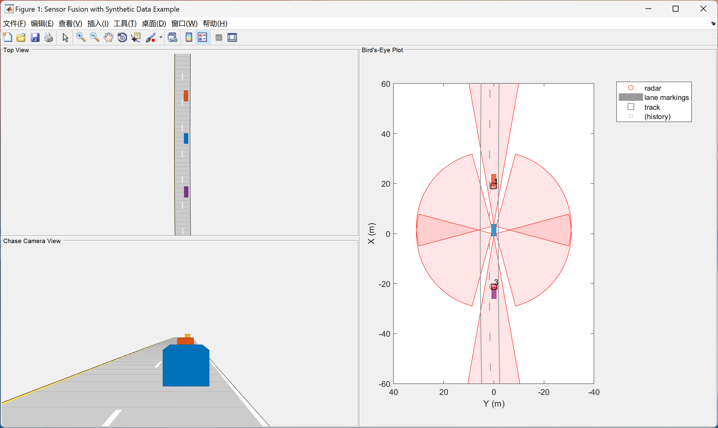
%% Define Radar Sensors
%
% The ego vehicle is equipped with a
% long-range radar sensor. Each side of the vehicle has two short-range radar
% sensors, each covering 90 degrees. One sensor on each side covers from
% the middle of the vehicle to the back. The other sensor on each side
% covers from the middle of the vehicle forward. The figure in the next
% section shows the coverage.
sensors = cell(6,1);
% Front-facing long-range radar sensor at the center of the front bumper of the car.
sensors{1} = radarDetectionGenerator('SensorIndex', 1, 'Height', 0.2, 'MaxRange', 174, ...
'SensorLocation', [egoCar.Wheelbase + egoCar.FrontOverhang, 0], 'FieldOfView', [20, 5]);
% Rear-facing long-range radar sensor at the center of the rear bumper of the car.
sensors{2} = radarDetectionGenerator('SensorIndex', 2, 'Height', 0.2, 'Yaw', 180, ...
'SensorLocation', [-egoCar.RearOverhang, 0], 'MaxRange', 174, 'FieldOfView', [20, 5]);
% Rear-left-facing short-range radar sensor at the left rear wheel well of the car.
sensors{3} = radarDetectionGenerator('SensorIndex', 3, 'Height', 0.2, 'Yaw', 120, ...
'SensorLocation', [0, egoCar.Width/2], 'MaxRange', 30, 'ReferenceRange', 50, ...
'FieldOfView', [90, 5], 'AzimuthResolution', 10, 'RangeResolution', 1.25);
🎉3 参考文献
文章中一些内容引自网络,会注明出处或引用为参考文献,难免有未尽之处,如有不妥,请随时联系删除。
[1]李文姣.基于卡尔曼滤波器的抗遮挡车辆跟踪算法[D].中国海洋大学,2013.
[2]陈猛.基于AIMM与特征融合的车辆跟踪算法研究及实现[D].西南交通大学,2011.
🌈4 Matlab代码实现


 548
548

 被折叠的 条评论
为什么被折叠?
被折叠的 条评论
为什么被折叠?
 到【灌水乐园】发言


