前言
本篇文章介绍的是ROS高效进阶内容,使用URDF 语言(xml格式)做一个差速轮式机器人模型,并使用URDF的增强版xacro,对机器人模型文件进行二次优化。
差速轮式机器人:两轮差速底盘由两个动力轮位于底盘左右两侧,两轮独立控制速度,通过给定不同速度实现底盘转向控制。一般会配有一到两个辅助支撑的万向轮。
此次建模,不引入算法,只是把机器人模型的样子做出来,所以只使用 rivz 进行可视化显示。
机器人的定义和构成
- 机器人定义:机器人是一种自动化的机器,所不同的是这种机器具备一些与人或生物相似的智能能力,如感知能力、规划能力、动作能力和协同能力,是一种具有高级灵活性的自动化机器。目前,自动驾驶汽车也被认为是一种机器人。
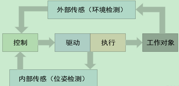
- 机器人构成:机器人通常分为四大部分,即执行机构,驱动系统,传感系统和控制系统。以自动驾驶汽车为例,执行机构就是油门,转向和刹车;驱动系统就是电动机;传感系统就是各种传感器:lidar,radar,camera,uss,imu,GNSS;控制系统就是智驾算法系统:感知,定位,规划和控制。
- 机器人四大部分的控制回路,大致如图:
URDF建模套路
- URDF:Unified Robot Description Format,统一的机器人描述文件格式。urdf 文件使用 xml 格式。
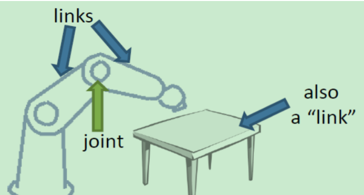
- 用 urdf 描述机器人,套路如下:每个机器人都是由多个 link(连杆) 和 joint(关节)组成。这里的 link 和joint 很宽泛,形状不一定是杆和轴。比如桌子,桌面和腿都是link,连接处是固定的 joint。
- link:描述机器人某个刚体部分的外观和物理属性。外观包括:尺寸,颜色,形状。物理属性包括:惯性矩阵(inertial matrix)和碰撞参数(collision properties)。在机器人建模中,每个link 都是一个坐标系。下面是差速轮式机器人底盘的建模,底盘一般称为 base。
<link name="base_link">
// visual 标签就是外观
<visual>
// base_link本身是个坐标系,这也是差速轮式机器人各组成部分的根坐标系,一般会把他的坐标原点设置在rviz的中心处
// origin表示底盘在其base_link坐标系下的原始位置和旋转状态
// xyz表示底盘质心在base_link坐标系的偏移位置,rpy(roll,pitch,yaw)是底盘绕base_link的x,y,z三个轴的旋转值
<origin xyz="0 0 0" rpy="0 0 0"/>
// geometry是物体几何外形
<geometry>
// 这里的底盘,用圆柱体表示,length值为高度,radius是半径值
<cylinder length="0.16" radius="0.2"/>
</geometry>
// material是材料,这里指定底盘颜色为红色,rgba是三色+透明度表示法,三色的范围是0~1,而不是0-255
<material name="red">
<color rgba="1 0 0 1"/>
</material>
</visual>
</link>
- 1.
- 2.
- 3.
- 4.
- 5.
- 6.
- 7.
- 8.
- 9.
- 10.
- 11.
- 12.
- 13.
- 14.
- 15.
- 16.
- 17.
- 18.
这里我们只进行外观建模,因此暂不涉及物理属性配置。
- joint:描述两个 link 之间的关系,包括运动学和动力学属性,这里暂时只关注运动学属性。通常情况下,两个 link 的关系一般分为六种:
continuous:旋转关节,可以围绕单轴360度无限旋转,比如轮子的轴
revolute:旋转关节,但是有旋转角度的范围限制,比如钟摆
prismatic:滑动关节,也叫活塞关节,沿某一轴线移动的关节,有位置限制,强调一维,比如打气筒
planar:平面关节,允许在平面正交方向上平移或旋转,强调平面,比如抽屉内外滑动
floating:浮动关节,允许进行平移和旋转运动,比如人体的肩关节
fixed:固定关节,比如桌子腿和桌面
下面是差速轮式机器人主动轮与底盘的 joint 样例:
// joint标签就是关节,type表示链接关系
<joint name="left_wheel_joint" type="continuous">
// origin表示轮子在base_link坐标系下的偏移和旋转
<origin xyz="0 0.19 -0.05" rpy="0 0 0" />
// 根link是底盘,子link是轮子
<parent link="base_link" />
<child link="left_wheel_link" />
// axis描述的轮子相对于其自身坐标系的 y 轴旋转,=
<axis xyz="0 1 0" />
</joint>
// 这是轮子link
<link name="left_wheel_link">
<visual>
// 轮子相当于其x轴,旋转90度,也就是立起来
<origin xyz="0 0 0" rpy="1.5707 0 0"/>
<geometry>
<cylinder length="0.06" radius="0.06"/>
</geometry>
<material name="white">
<color rgba="1 1 1 0.9"/>
</material>
</visual>
</link>
- 1.
- 2.
- 3.
- 4.
- 5.
- 6.
- 7.
- 8.
- 9.
- 10.
- 11.
- 12.
- 13.
- 14.
- 15.
- 16.
- 17.
- 18.
- 19.
- 20.
- 21.
- 22.
- 23.
- 24.
使用URDF做一个差速轮式机器人模型
- 创建 mbot_description 软件包及相关文件
cd ~/catkin_ws/src
catkin_create_pkg mbot_description urdf xacro
cd mbot_description
mkdir -p config doc launch meshes urdf/sensor
touch launch/display_mbot_urdf.launch launch/display_mbot_xacro.launch
touch urdf/mbot_base.urdf urdf/mbot_base.xacro
touch urdf/sensor/camera.xacro urdf/sensor/kinect.xacro urdf/sensor/laser.xacro
- 1.
- 2.
- 3.
- 4.
- 5.
- 6.
- 7.
- 8.
- mbot_base.urdf :这是整个mbot建模的文件,包括底盘,两个动力伦,两个万向轮,一个camera,一个kinect(深度相机),一个lidar。
<?xml version="1.0" ?>
<robot name="mbot">
<link name="base_link">
<visual>
<origin xyz="0 0 0" rpy="0 0 0"/>
<geometry>
<cylinder length="0.16" radius="0.2"/>
</geometry>
<material name="red">
<color rgba="1 0 0 1"/>
</material>
</visual>
</link>
<joint name="left_wheel_joint" type="continuous">
<origin xyz="0 0.19 -0.05" rpy="0 0 0" />
<parent link="base_link" />
<child link="left_wheel_link" />
<axis xyz="0 1 0" />
</joint>
<link name="left_wheel_link">
<visual>
<origin xyz="0 0 0" rpy="1.5707 0 0"/>
<geometry>
<cylinder length="0.06" radius="0.06"/>
</geometry>
<material name="white">
<color rgba="1 1 1 0.9"/>
</material>
</visual>
</link>
<joint name="right_wheel_joint" type="continuous">
<origin xyz="0 -0.19 -0.05" rpy="0 0 0" />
<parent link="base_link" />
<child link="right_wheel_link" />
<axis xyz="0 1 0" />
</joint>
<link name="right_wheel_link">
<visual>
<origin xyz="0 0 0" rpy="1.5707 0 0"/>
<geometry>
<cylinder length="0.025" radius="0.06" />
</geometry>
<material name="white">
<color rgba="1 1 1 0.9"/>
</material>
</visual>
</link>
<joint name="front_caster_joint" type="continuous">
<origin xyz="0.18 0 -0.095" rpy="0 0 0" />
<parent link="base_link"/>
<child link="front_caster_link" />
<axis xyz="0 1 0" />
</joint>
<link name="front_caster_link">
<visual>
<origin xyz="0 0 0" rpy="0 0 0" />
<geometry>
<sphere radius="0.015" />
</geometry>
<material name="white">
<color rgba="1 1 1 0.9"/>
</material>
</visual>
</link>
<joint name="back_caster_joint" type="continuous">
<origin xyz="-0.18 0 -0.095" rpy="0 0 0" />
<parent link="base_link"/>
<child link="back_caster_link" />
<axis xyz="0 1 0" />
</joint>
<link name="back_caster_link">
<visual>
<origin xyz="0 0 0" rpy="0 0 0" />
<geometry>
<sphere radius="0.015" />
</geometry>
<material name="white">
<color rgba="1 1 1 0.9"/>
</material>
</visual>
</link>
<joint name="camera_joint" type="fixed">
<origin xyz="-0.17 0 0.1" rpy="0 0 0" />
<parent link="base_link"/>
<child link="camera_link" />
</joint>
<link name="camera_link">
<visual>
<origin xyz="0 0 0" rpy="0 0 0" />
<geometry>
<box size="0.03 0.04 0.04" />
</geometry>
<material name="grey">
<color rgba="0.5 0.5 0.5 1"/>
</material>
</visual>
</link>
<joint name="stage_joint" type="fixed">
<origin xyz="0 0 0.14" rpy="0 0 0" />
<parent link="base_link"/>
<child link="stage_link" />
</joint>
<link name="stage_link">
<visual>
<origin xyz="0 0 0" rpy="0 0 0"/>
<geometry>
<cylinder length="0.12" radius="0.1"/>
</geometry>
<material name="red">
<color rgba="1 0 0 1"/>
</material>
</visual>
</link>
<joint name="laser_joint" type="fixed">
<origin xyz="0 0 0.085" rpy="0 0 0" />
<parent link="stage_link"/>
<child link="laser_link" />
</joint>
<link name="laser_link">
<visual>
<origin xyz="0 0 0" rpy="0 0 0" />
<geometry>
<cylinder length="0.05" radius="0.05"/>
</geometry>
<material name="grey">
<color rgba="0.5 0.5 0.5 1"/>
</material>
</visual>
</link>
<joint name="kinect_joint" type="fixed">
<origin xyz="0.15 0 0.11" rpy="0 0 0" />
<parent link="base_link"/>
<child link="kinect_link" />
</joint>
<link name="kinect_link">
<visual>
<origin xyz="0 0 0" rpy="0 0 1.5708" />
<geometry>
// 使用三维软件导出的模型文件
<mesh filename="package://mbot_description/meshes/kinect.dae" />
</geometry>
</visual>
</link>
</robot>
- 1.
- 2.
- 3.
- 4.
- 5.
- 6.
- 7.
- 8.
- 9.
- 10.
- 11.
- 12.
- 13.
- 14.
- 15.
- 16.
- 17.
- 18.
- 19.
- 20.
- 21.
- 22.
- 23.
- 24.
- 25.
- 26.
- 27.
- 28.
- 29.
- 30.
- 31.
- 32.
- 33.
- 34.
- 35.
- 36.
- 37.
- 38.
- 39.
- 40.
- 41.
- 42.
- 43.
- 44.
- 45.
- 46.
- 47.
- 48.
- 49.
- 50.
- 51.
- 52.
- 53.
- 54.
- 55.
- 56.
- 57.
- 58.
- 59.
- 60.
- 61.
- 62.
- 63.
- 64.
- 65.
- 66.
- 67.
- 68.
- 69.
- 70.
- 71.
- 72.
- 73.
- 74.
- 75.
- 76.
- 77.
- 78.
- 79.
- 80.
- 81.
- 82.
- 83.
- 84.
- 85.
- 86.
- 87.
- 88.
- 89.
- 90.
- 91.
- 92.
- 93.
- 94.
- 95.
- 96.
- 97.
- 98.
- 99.
- 100.
- 101.
- 102.
- 103.
- 104.
- 105.
- 106.
- 107.
- 108.
- 109.
- 110.
- 111.
- 112.
- 113.
- 114.
- 115.
- 116.
- 117.
- 118.
- 119.
- 120.
- 121.
- 122.
- 123.
- 124.
- 125.
- 126.
- 127.
- 128.
- 129.
- 130.
- 131.
- 132.
- 133.
- 134.
- 135.
- 136.
- 137.
- 138.
- 139.
- 140.
- 141.
- 142.
- 143.
- 144.
- 145.
- 146.
- 147.
- 148.
- 149.
- 150.
- 151.
- 152.
- 153.
- 154.
- 155.
- 156.
- 157.
- 158.
- 159.
- 160.
- 161.
- display_mbot_urdf.launch
<launch>
// 设置ros的全局参数robot_description,指定机器人模型文件
<param name="robot_description" textfile="$(find mbot_description)/urdf/mbot_base.urdf" />
<!-- 设置GUI参数,显示关节控制插件 -->
// 用这个可以控制机器人关节,但本文的demo没看到这个,有点遗憾
<param name="use_gui" value="true"/>
<!-- 运行joint_state_publisher节点,发布机器人的关节状态 -->
<node name="joint_state_publisher" pkg="joint_state_publisher" type="joint_state_publisher" />
<!-- 运行robot_state_publisher节点,发布tf -->
<node name="robot_state_publisher" pkg="robot_state_publisher" type="robot_state_publisher" />
// robot_state_publisher结合joint_state_publisher可以实时把机器人各关节和各坐标系关系发布出来,让rviz显示。如果不设置,rviz无法完整加载机器人模型。
// rviz显示后会生成配置文件,保存后再打开,就不用频繁设置了。
<!-- 运行rviz可视化界面 -->
<node name="rviz" pkg="rviz" type="rviz" args="-d $(find mbot_description)/config/mbot_urdf.rviz" required="true" />
</launch>
- 1.
- 2.
- 3.
- 4.
- 5.
- 6.
- 7.
- 8.
- 9.
- 10.
- 11.
- 12.
- 13.
- 14.
- 15.
- 16.
- 17.
- 18.
- 19.
- 20.
- 使用 urdf_to_graphiz 命令行工具可以把 urdf 文件的内容,以树的样子dump出来,格式是pdf。使用这个可以快速读取 urdf 的 link 和 joint,下图是上面例子的节点树状图。
- 编译和运行
使用xacro优化差速轮式机器人模型
- 原始的urdf语法比较简单,导致机器人模型文件比较冗长啰嗦,比如两个动力轮,两个万向轮的编写就非常重复。ROS 提出了xacro语法,让机器人模型文件具有可编程能力,比如设置参数,定义宏函数并调用,文件包含等。下面进行分类举例:设置并调用参数:
设置宏函数并调用:
// xacro:macro设置宏函数,名字是wheel,参数是prefix 和 reflect
<xacro:macro name="wheel" params="prefix reflect">
<joint name="${prefix}_wheel_joint" type="continuous">
<origin xyz="${wheel_joint_x} ${reflect*wheel_joint_y} ${-wheel_joint_z}" rpy="0 0 0" />
<parent link="base_link" />
<child link="${prefix}_wheel_link" />
<axis xyz="0 1 0" />
</joint>
<link name="${prefix}_wheel_link">
<visual>
<origin xyz="0 0 0" rpy="${M_PI/2} 0 0"/>
<geometry>
<cylinder length="${wheel_length}" radius="${wheel_radius}"/>
</geometry>
<material name="white" />
</visual>
</link>
</xacro:macro>
// 调用wheel宏函数
<xacro:wheel prefix="left" reflect="1"/>
<xacro:wheel prefix="right" reflect="-1"/>
- 1.
- 2.
- 3.
- 4.
- 5.
- 6.
- 7.
- 8.
- 9.
- 10.
- 11.
- 12.
- 13.
- 14.
- 15.
- 16.
- 17.
- 18.
- 19.
- 20.
- 21.
- 22.
文件包含
- 这里的几个文件是对上面的mbot_base.urdf的重写,使用xacro,具体语法看上面的解释。mbot_base.xacro
<?xml version="1.0" ?>
<robot name="mbot" xmlns:xacro="http://www.ros.org/wiki/xacro">
<xacro:property name="M_PI" value="3.1415926" />
<xacro:property name="wheel_joint_x" value="0" />
<xacro:property name="wheel_joint_y" value="0.19" />
<xacro:property name="wheel_joint_z" value="0.05" />
<xacro:property name="wheel_length" value="0.06" />
<xacro:property name="wheel_radius" value="0.06" />
<xacro:property name="caster_joint_x" value="0.18" />
<xacro:property name="caster_joint_y" value="0" />
<xacro:property name="caster_joint_z" value="0.095" />
<xacro:property name="caster_radius" value="0.015" />
<xacro:property name="base_length" value="0.16" />
<xacro:property name="base_radius" value="0.2" />
<xacro:property name="stage_length" value="0.12" />
<xacro:property name="stage_radius" value="0.1" />
<xacro:property name="camera_joint_x" value="0.17" />
<xacro:property name="camera_joint_y" value="0" />
<xacro:property name="camera_joint_z" value="0.1" />
<xacro:property name="kinect_joint_x" value="0.15" />
<xacro:property name="kinect_joint_y" value="0" />
<xacro:property name="kinect_joint_z" value="0.11" />
<xacro:property name="laser_joint_x" value="0" />
<xacro:property name="laser_joint_y" value="0" />
<xacro:property name="laser_joint_z" value="0.085" />
<material name="white">
<color rgba="1 1 1 0.9"/>
</material>
<material name="red">
<color rgba="1 0 0 1"/>
</material>
<material name="grey">
<color rgba="0.5 0.5 0.5 1"/>
</material>
<xacro:macro name="base_stage">
<link name="base_link">
<visual>
<origin xyz="0 0 0" rpy="0 0 0"/>
<geometry>
<cylinder length="${base_length}" radius="${base_radius}"/>
</geometry>
<material name="red" />
</visual>
</link>
<joint name="stage_joint" type="fixed">
<origin xyz="0 0 ${(base_length + stage_length)/2}" rpy="0 0 0" />
<parent link="base_link"/>
<child link="stage_link" />
</joint>
<link name="stage_link">
<visual>
<origin xyz="0 0 0" rpy="0 0 0"/>
<geometry>
<cylinder length="${stage_length}" radius="${stage_radius}"/>
</geometry>
<material name="red" />
</visual>
</link>
</xacro:macro>
<xacro:macro name="wheel" params="prefix reflect">
<joint name="${prefix}_wheel_joint" type="continuous">
<origin xyz="${wheel_joint_x} ${reflect*wheel_joint_y} ${-wheel_joint_z}" rpy="0 0 0" />
<parent link="base_link" />
<child link="${prefix}_wheel_link" />
<axis xyz="0 1 0" />
</joint>
<link name="${prefix}_wheel_link">
<visual>
<origin xyz="0 0 0" rpy="${M_PI/2} 0 0"/>
<geometry>
<cylinder length="${wheel_length}" radius="${wheel_radius}"/>
</geometry>
<material name="white" />
</visual>
</link>
</xacro:macro>
<xacro:macro name="caster" params="prefix reflect">
<joint name="${prefix}_caster_joint" type="continuous">
<origin xyz="${reflect*caster_joint_x} ${caster_joint_y} ${-caster_joint_z}" rpy="0 0 0" />
<parent link="base_link"/>
<child link="${prefix}_caster_link" />
<axis xyz="0 1 0" />
</joint>
<link name="${prefix}_caster_link">
<visual>
<origin xyz="0 0 0" rpy="0 0 0" />
<geometry>
<sphere radius="${caster_radius}" />
</geometry>
<material name="white" />
</visual>
</link>
</xacro:macro>
<xacro:base_stage />
<xacro:wheel prefix="left" reflect="1"/>
<xacro:wheel prefix="right" reflect="-1"/>
<xacro:caster prefix="front" reflect="1"/>
<xacro:caster prefix="back" reflect="-1"/>
<xacro:include filename="$(find mbot_description)/urdf/sensor/camera.xacro" />
<xacro:usb_camera joint_x="${camera_joint_x}" joint_y="${camera_joint_y}" joint_z="${camera_joint_z}"/>
<xacro:include filename="$(find mbot_description)/urdf/sensor/kinect.xacro" />
<xacro:kinect joint_x="${kinect_joint_x}" joint_y="${kinect_joint_y}" joint_z="${kinect_joint_z}"/>
<xacro:include filename="$(find mbot_description)/urdf/sensor/laser.xacro" />
<xacro:laser joint_x="${laser_joint_x}" joint_y="${laser_joint_y}" joint_z="${laser_joint_z}"/>
</robot>
- 1.
- 2.
- 3.
- 4.
- 5.
- 6.
- 7.
- 8.
- 9.
- 10.
- 11.
- 12.
- 13.
- 14.
- 15.
- 16.
- 17.
- 18.
- 19.
- 20.
- 21.
- 22.
- 23.
- 24.
- 25.
- 26.
- 27.
- 28.
- 29.
- 30.
- 31.
- 32.
- 33.
- 34.
- 35.
- 36.
- 37.
- 38.
- 39.
- 40.
- 41.
- 42.
- 43.
- 44.
- 45.
- 46.
- 47.
- 48.
- 49.
- 50.
- 51.
- 52.
- 53.
- 54.
- 55.
- 56.
- 57.
- 58.
- 59.
- 60.
- 61.
- 62.
- 63.
- 64.
- 65.
- 66.
- 67.
- 68.
- 69.
- 70.
- 71.
- 72.
- 73.
- 74.
- 75.
- 76.
- 77.
- 78.
- 79.
- 80.
- 81.
- 82.
- 83.
- 84.
- 85.
- 86.
- 87.
- 88.
- 89.
- 90.
- 91.
- 92.
- 93.
- 94.
- 95.
- 96.
- 97.
- 98.
- 99.
- 100.
- 101.
- 102.
- 103.
- 104.
- 105.
- 106.
- 107.
- 108.
- 109.
- 110.
- 111.
- 112.
- 113.
- 114.
- 115.
- 116.
- 117.
- 118.
- 119.
- 120.
- 121.
- 122.
- 123.
- 124.
- 125.
- 126.
- 127.
- 128.
- 129.
camera.xacro
<?xml version="1.0" ?>
<robot name="mbot" xmlns:xacro="http://www.ros.org/wiki/xacro">
<xacro:macro name="usb_camera" params="joint_x joint_y joint_z">
<joint name="camera_joint" type="fixed">
<origin xyz="${-joint_x} ${joint_y} ${joint_z}" rpy="0 0 0" />
<parent link="base_link"/>
<child link="camera_link" />
</joint>
<link name="camera_link">
<visual>
<origin xyz="0 0 0" rpy="0 0 0" />
<geometry>
<box size="0.03 0.04 0.04" />
</geometry>
<material name="grey" />
</visual>
</link>
</xacro:macro>
</robot>
- 1.
- 2.
- 3.
- 4.
- 5.
- 6.
- 7.
- 8.
- 9.
- 10.
- 11.
- 12.
- 13.
- 14.
- 15.
- 16.
- 17.
- 18.
- 19.
- 20.
kinect.xacro
<?xml version="1.0" ?>
<robot name="mbot" xmlns:xacro="http://www.ros.org/wiki/xacro">
<xacro:macro name="kinect" params="joint_x joint_y joint_z">
<joint name="kinect_joint" type="fixed">
<origin xyz="${joint_x} ${joint_y} ${joint_z}" rpy="0 0 0" />
<parent link="base_link"/>
<child link="kinect_link" />
</joint>
<link name="kinect_link">
<visual>
<origin xyz="0 0 0" rpy="0 0 1.5708" />
<geometry>
<mesh filename="package://mbot_description/meshes/kinect.dae" />
</geometry>
</visual>
</link>
</xacro:macro>
</robot>
- 1.
- 2.
- 3.
- 4.
- 5.
- 6.
- 7.
- 8.
- 9.
- 10.
- 11.
- 12.
- 13.
- 14.
- 15.
- 16.
- 17.
- 18.
- 19.
- 20.
- 21.
laser.xacro
<?xml version="1.0" ?>
<robot name="mbot" xmlns:xacro="http://www.ros.org/wiki/xacro">
<xacro:macro name="laser" params="joint_x joint_y joint_z">
<joint name="laser_joint" type="fixed">
<origin xyz="${joint_x} ${joint_y} ${joint_z}" rpy="0 0 0" />
<parent link="stage_link"/>
<child link="laser_link" />
</joint>
<link name="laser_link">
<visual>
<origin xyz="0 0 0" rpy="0 0 0" />
<geometry>
<cylinder length="0.05" radius="0.05"/>
</geometry>
<material name="grey"/>
</visual>
</link>
</xacro:macro>
</robot>
- 1.
- 2.
- 3.
- 4.
- 5.
- 6.
- 7.
- 8.
- 9.
- 10.
- 11.
- 12.
- 13.
- 14.
- 15.
- 16.
- 17.
- 18.
- 19.
- 20.
- 21.
- display_mbot_xacro.launch
<launch>
// 引入xacro的解释器,不然无法读取 .xacro文件
<arg name="model" default="$(find xacro)/xacro '$(find mbot_description)/urdf/mbot_base.xacro'" />
<param name="robot_description" command="$(arg model)" />
<!-- 设置GUI参数,显示关节控制插件 -->
<param name="use_gui" value="true"/>
<!-- 运行joint_state_publisher节点,发布机器人的关节状态 -->
<node name="joint_state_publisher" pkg="joint_state_publisher" type="joint_state_publisher" />
<!-- 运行robot_state_publisher节点,发布tf -->
<node name="robot_state_publisher" pkg="robot_state_publisher" type="robot_state_publisher" />
<!-- 运行rviz可视化界面 -->
<node name="rviz" pkg="rviz" type="rviz" args="-d $(find mbot_description)/config/mbot_xacro.rviz" required="true" />
</launch>
- 1.
- 2.
- 3.
- 4.
- 5.
- 6.
- 7.
- 8.
- 9.
- 10.
- 11.
- 12.
- 13.
- 14.
- 15.
- 16.
- 17.
- 18.
- 19.
- 运行效果如下,这里显示了坐标系轴
部分配置代码