


 本文介绍了一个基于嵌入式系统的ADC初始化配置与DMA数据传输的集成应用案例。详细解析了ADC通道设置、时钟配置、扫描模式、参考源设定及数据范围设置,并演示了如何通过DMA进行高效数据传输,包括DMA中断向量、数据长度、地址模式、块大小等关键参数的设置。
#include "BAT32G137.h"
#include "adc.h"
#include "cg_tmm.h"
#include "elc.h"
#include "dma.h"


// bref: ADC DMA扫描
// para:
// note:
static void adc_init(void)
{
	//  开启ADC外设
    CGC->PER0 |= CGC_PER0_ADCEN_Msk;    /* enables input clock supply */
	// 停止ADC
    ADC->ADM0  = 0x00U;                 /* disable AD conversion and clear ADM0 register */

	// 设置ADC 通道
    /* A/D input pin setting: Please modify the following code according to your application needs. */
	// 所有的IO设置为 模拟通道
    /* Set ANI0(P20) pin: It is necessary for ADC_VREF_AVREFP_AVREFM, used as AVREFP */
    PORT->PMC2 |= 0x01U;
    /* Set ANI1(P21) pin: It is necessary for ADC_VREF_AVREFP_AVREFM, used as AVREFM */
    PORT->PMC2 |= 0x02U;
    /* Set ANI2(P22) pin */
    PORT->PMC2 |= 0x04U;
    /* Set ANI3(P23) pin */
    PORT->PMC2 |= 0x08U;

	// 设置ADC时钟
    /* AD operation mode: select or scan mode  */
    ADC->ADM0 = _28_AD_CONVERSION_CLOCK_1 | _00_AD_COMPARATOR_DISABLE;
    /* AD conversion mode setting */
    // ADM1.0为0为四个通道 为1 是单个通道
	// 扫描模式
	ADC->ADM1 |= _80_AD_OPERMODE_SCAN; //
	// ADC参考源设定
	ADC->ADM2 = _00_AD_POSITIVE_VDD | _00_AD_NEGATIVE_VSS | _00_AD_AREA_MODE_1 ;
	// 数据值范围
    /* AD comversion result comprision upper limit setting */
    ADC->ADUL = _FF_AD_ADUL_VALUE;
    /* AD comversion result comprision lower limit setting */
    ADC->ADLL = _00_AD_ADLL_VALUE;
	// 采样率 15.5 ADCLK
	ADC->ADNSMP = 0x0F;
//    /* adhard power up */
    ADC->ADM0 |= ADCE;
	// 通道选择或者通道组选择
	ADC->ADS = 0x00;
	// 软件触发
	ADC->ADTRG = _00_AD_TRIGGER_SOFTWARE;
}

static void gpio_init(void)
{
	// P50
	PORT->POM5 &= ~(1<<0);

	PORT->PM5 &= ~(1<<0);
	PORT->P5 |= (1<<0);
	//PORT->P5 &= ~(1<<0);
}

static uint16_t adc_buff[8];

static void dma_init(void)
{
	const uint8_t ctrl_data_num = 0;

	// DMA_VECTOR_ADC DMA中断向量位置
	DMAVEC->VEC[DMA_VECTOR_ADC] = ctrl_data_num;
	// CTRL_DMACR_SZ_Pos 数据长度(1表示16位 应为ADC结果大于8位,所以选16位)
	// CTRL_DMACR_RPTINT_Pos 不使用链式触发(所谓的链传输设置过后执行完会自动提取紧挨的DMA信息块)
	// CTRL_DMACR_DAMOD_Pos 目标地址是否增加 1表示增加
	// CTRL_DMACR_SAMOD_Pos 源地址是否增加 0表示不增加
	// CTRL_DMACR_RPTSEL_Pos DMA传输的方向 0表示为 从源地址提取到目标地址
	// CTRL_DMACR_MODE_Pos  1 表示否则一直执行 循环模式还是单次模式
	DMAVEC->CTRL[ctrl_data_num].DMACR = (1 << CTRL_DMACR_SZ_Pos) | (0 << CTRL_DMACR_RPTINT_Pos)|
									(1 << CTRL_DMACR_DAMOD_Pos)  | (0 << CTRL_DMACR_SAMOD_Pos) |
									(0 << CTRL_DMACR_RPTSEL_Pos)| (1 << CTRL_DMACR_MODE_Pos);
	// 块大小
	DMAVEC->CTRL[ctrl_data_num].DMBLS = 1;
	// 每个DMA循环传输次数
	DMAVEC->CTRL[ctrl_data_num].DMACT = 4;
	// DMA 传输重载值
	DMAVEC->CTRL[ctrl_data_num].DMRLD = 4;
	// DMA传输源地址
	DMAVEC->CTRL[ctrl_data_num].DMSAR = (uint32_t)&ADC->ADCR;
	// DMA传输目标地址
	DMAVEC->CTRL[ctrl_data_num].DMDAR = (uint32_t)&adc_buff[0];

	/* init DMA registers */
	// 开启 DMA时钟
	CGC->PER1   |= CGC_PER1_DMAEN_Msk;
	// 指定信息块内置地址
	DMA->DMABAR  = DMAVEC_BASE;
	// 开启对应的 DMA
	DMA->DMAEN1 |= 1 << 2;
}

int main(void)
{
	SystemCoreClockUpdate();
	gpio_init();

	adc_init();
	dma_init();
	ADC->ADM0 |= ADCS;
	while(1)
	{

	}
}
ADC速率为1.2M。
高速模式ADC转换周期为31.5 ADCLK。
低电流模式ADC转换周期为40.5 ADCLK。
硬件等待是等待ADC电源稳定为1us.
可以设置外部触发。
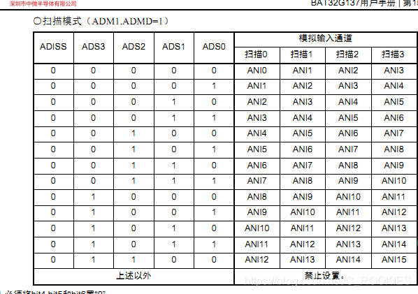
注意每次扫描模式是扫描四个通道。


 1004
1004

 被折叠的 条评论
为什么被折叠?
被折叠的 条评论
为什么被折叠?
 到【灌水乐园】发言


