 AXI接口事务传输行为与顺序


The following diagram shows a time representation of several valid transactions on the five
channels of an AXI3 or AXI4 interface:
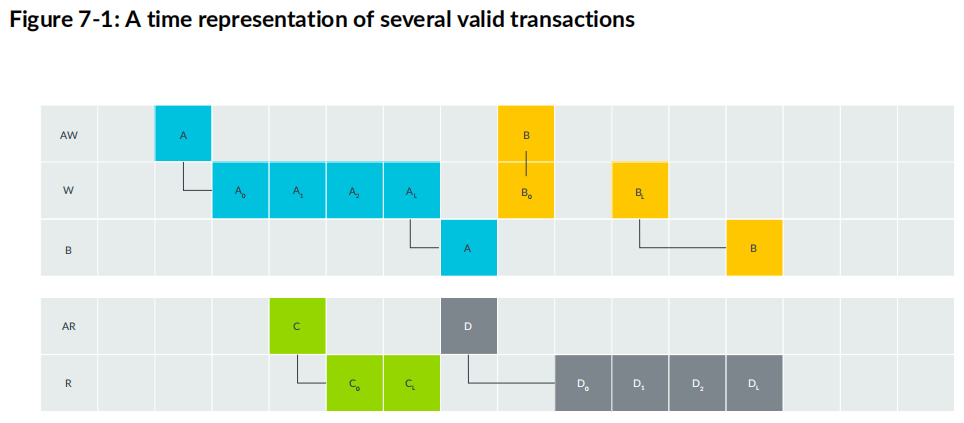
The different transactions in this example are as follows:
- Transaction A, which is a write transaction that contains four transfers. The manager first puts
the address A on the AW channel, then soon puts the sequence of four data transfers on the
W channel, ending with AL where L stands for last. Once all four data transfers complete, the
subordinate responds on the channel. - While transaction A was occurring, the manager also used the read channels to perform a read
transaction, C, which contains two transfers. Because this is a read transaction, there is no
response from the subordinate on a different channel when the transaction completes. Instead,
the response from the subordinate is included in the R channel at the same time as the data. - Once transaction C completes, the manager uses the Read Address channel AR to send a
new read address, D, to the subordinate. In this case, the response from the subordinate
is not immediate. This is indicated by the empty time slot between D and D0. Delays like
this can happen. The subordinate is not obliged to answer immediately. For example, the
subordinate could be busy performing another operation, or it could take time to retrieve the
data. Eventually, the subordinate responds with four sequential transfers, D0 through DL, on
the R channel. - Finally, while the read transaction D is ongoing, the manager uses the Write Address channel,
AW, to send a new address, B, to the subordinate for a write operation. The manager puts
the data B0 on the W channel at the same time as it puts the corresponding address B on the
AW channel. There is a delay in this example between data transfers B0 and BL, and another
delay before the response B. The transaction completes only when the subordinate sends the
response to the manager. All of these examples are valid transactions.


 387
387

 被折叠的 条评论
为什么被折叠?
被折叠的 条评论
为什么被折叠?
 到【灌水乐园】发言


