


 This blog focuses on writing testbenches for digital design modules in Verilog. It guides through creating testbenches for an AND gate, a module with specific output waveforms, and a T flip-flop, ensuring all necessary input combinations and functionalities are tested."
110693523,10297088,Python Selenium保存网页为PDF的挑战与解决方案,"['Python开发', 'Selenium框架', 'Web自动化', 'PDF转换']
This blog focuses on writing testbenches for digital design modules in Verilog. It guides through creating testbenches for an AND gate, a module with specific output waveforms, and a T flip-flop, ensuring all necessary input combinations and functionalities are tested."
110693523,10297088,Python Selenium保存网页为PDF的挑战与解决方案,"['Python开发', 'Selenium框架', 'Web自动化', 'PDF转换']
You are provided a module with the following declaration:
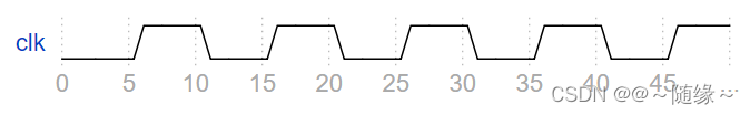
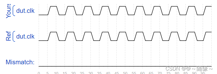
module dut ( input clk ) ;
Write a testbench that creates one instance of module dut (with any instance name), and create a clock signal to drive the module's clkinput. The clock has a period of 10 ps. The clock should be initialized to zero with its first transition being 0 to 1.
module top_module ();

    reg clk;
    initial begin
        clk = 1'b0;
    end
    always #5 clk = ~clk;

    dut u0(clk);

endmodule
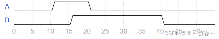
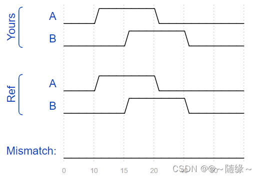
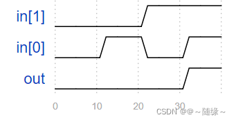
Create a Verilog testbench that will produce the following waveform for outputs A and B
module top_module ( output reg A, output reg B );//
    // generate input patterns here
    initial begin
        A=1'b0;
        B=1'b0;
        #10 A=1'b1;
        #5 B=1'b1;
        #5 A=1'b0;
        #20 B=1'b0;
    end
endmodule
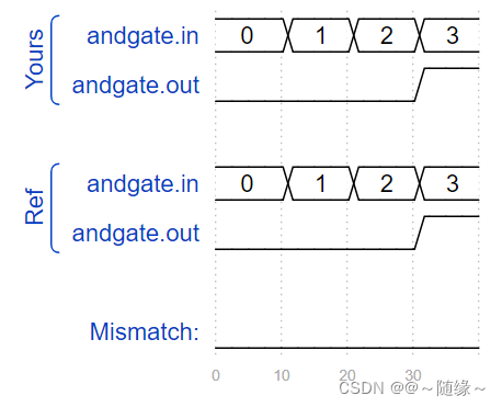
You are given the following AND gate you wish to test:
module andgate (
    input [1:0] in,
    output out
);
Write a testbench that instantiates this AND gate and tests all 4 input combinations, by generating the following timing diagram:
module top_module();
    reg [1:0] in;
    reg out;
    initial begin
        in[0]=1'b0;
        in[1]=1'b0;
        #10 in[0]=1'b1;
        #10 in[0]=1'b0;
            in[1]=1'b1;
        #10 in[0]=1'b1;
        in[1]=1'b1;
    end
    andgate u0(
        .in(in),
        .out(out)
    );
endmodule
The waveform below sets clk, in, and s:
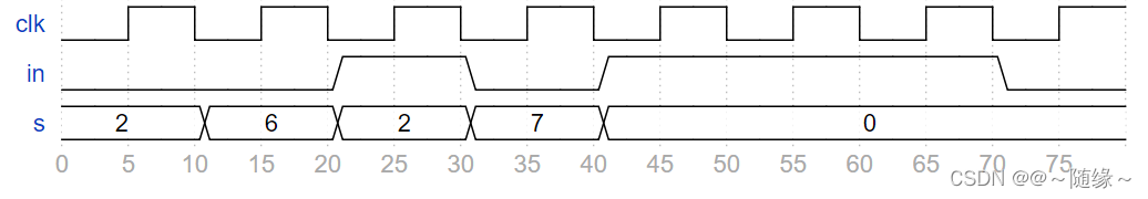
Module q7 has the following declaration:
module q7 (
    input clk,
    input in,
    input [2:0] s,
    output out
);
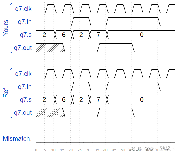
Write a testbench that instantiates module q7 and generates these input signals exactly as shown in the waveform above.
module top_module();
    reg clk;
    reg in;
    reg [2:0] s;
    reg out;
    initial begin
        clk=1'b0;
        in=1'b0;
        s=3'd2;
        #10 s=3'd6;
        #10
        in=1'b1;
        s=3'd2;
        #10
        in=1'b0;
        s=3'd7;
        #10
        in=1'b1;
        s=3'd0;
        #30 in=1'b0;
    end
    always #5 clk=~clk;
    q7 u0(
        .clk(clk),
        .in(in),
        .s(s),
        .out(out)
);
endmodule
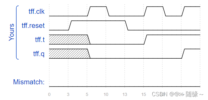
You are given a T flip-flop module with the following declaration:
module tff (
    input clk,
    input reset,   // active-high synchronous reset
    input t,       // toggle
    output q
);
Write a testbench that instantiates one tff and will reset the T flip-flop then toggle it to the "1" state.
module top_module ();
reg clk,reset,t;
    wire q;
    initial begin
        clk=1'b0;
        reset=1'b0;
        #3
        reset=1'b1;
        #10
        reset=1'b0;
    end
    always #5 clk=~clk;
    always @(posedge clk) begin
        if(reset)
            t<=1'b0;
        else
            t<=1'b1;
    end
     tff u0(
         .clk(clk),
         .reset(reset),   // active-high synchronous reset
         .t(t),       // toggle
         .q(q)
);
endmodule


 245
245

 被折叠的 条评论
为什么被折叠?
被折叠的 条评论
为什么被折叠?
 到【灌水乐园】发言


