


 本文介绍了两种细胞自动机——规则110和生命游戏的实现。规则110中,每个细胞的状态根据其两个相邻细胞的状态进行变化。而在生命游戏中,细胞状态基于其周围八个邻居的状态更新。文章提供了Verilog代码实现,用于在一个16x16的环状网格上模拟这些规则,并在每个时钟周期推进一步。
At each time step, the next state of each cell is the XOR of the cell's two current neighbours. A more verbose way of expressing this rule is the following table, where a cell's next state is a function of itself and its two neighbours:
| Left | Center | Right | Center's next state |
|---|---|---|---|
| 1 | 1 | 1 | 0 |
| 1 | 1 | 0 | 1 |
| 1 | 0 | 1 | 0 |
| 1 | 0 | 0 | 1 |
| 0 | 1 | 1 | 1 |
| 0 | 1 | 0 | 0 |
| 0 | 0 | 1 | 1 |
| 0 | 0 | 0 | 0 |
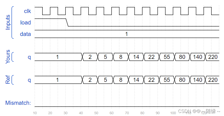
In this circuit, create a 512-cell system (q[511:0]), and advance by one time step each clock cycle. The load input indicates the state of the system should be loaded with data[511:0]. Assume the boundaries (q[-1] and q[512]) are both zero (off).
module top_module(
    input clk,
    input load,
    input [511:0] data,
    output [511:0] q );
    always @(posedge clk)begin
        if(load)begin
            q <= data;
        end
        else begin
            q <= {1'b0,q[511:1]}^{q[510:0],1'b0};
        end
    end

endmodule
At each time step, the state of each cell changes. In Rule 110, the next state of each cell depends only on itself and its two neighbours, according to the following table:
| Left | Center | Right | Center's next state |
|---|---|---|---|
| 1 | 1 | 1 | 0 |
| 1 | 1 | 0 | 1 |
| 1 | 0 | 1 | 1 |
| 1 | 0 | 0 | 0 |
| 0 | 1 | 1 | 1 |
| 0 | 1 | 0 | 1 |
| 0 | 0 | 1 | 1 |
| 0 | 0 | 0 | 0 |
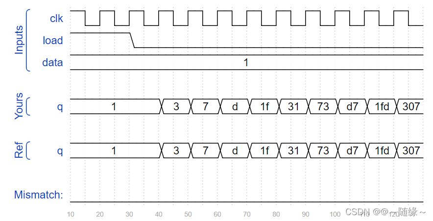
In this circuit, create a 512-cell system (q[511:0]), and advance by one time step each clock cycle. The load input indicates the state of the system should be loaded with data[511:0]. Assume the boundaries (q[-1] and q[512]) are both zero (off).
module top_module(
    input clk,
    input load,
    input [511:0] data,
    output [511:0] q
);
    always @(posedge clk) begin
        if(load)
            q<=data;
        else
            q<=(~{1'b0,q[511:1]}&q)|(q&~{q[510:0],1'b0})|{~{1'b0,q[511:1]}&{q[510:0],1'b0}}|{~q&{q[510:0],1'b0}};
    end
endmodule
The "game" is played on a two-dimensional grid of cells, where each cell is either 1 (alive) or 0 (dead). At each time step, each cell changes state depending on how many neighbours it has:
- 0-1 neighbour: Cell becomes 0.
- 2 neighbours: Cell state does not change.
- 3 neighbours: Cell becomes 1.
- 4+ neighbours: Cell becomes 0.
The game is formulated for an infinite grid. In this circuit, we will use a 16x16 grid. To make things more interesting, we will use a 16x16 toroid, where the sides wrap around to the other side of the grid. For example, the corner cell (0,0) has 8 neighbours: (15,1), (15,0), (15,15), (0,1), (0,15), (1,1), (1,0), and (1,15). The 16x16 grid is represented by a length 256 vector, where each row of 16 cells is represented by a sub-vector: q[15:0] is row 0, q[31:16] is row 1, etc. (This tool accepts SystemVerilog, so you may use 2D vectors if you wish.)
- load: Loads data into q at the next clock edge, for loading initial state.
- q: The 16x16 current state of the game, updated every clock cycle.
The game state should advance by one timestep every clock cycle.
一个中心点周围有8个邻居,如果周围的邻居中1的数目为0-1个,那么中心点变为0;如果周围邻居中1的数目为2个,那么中心点状态不变;如果周围邻居中1的数目为3个,中心点变为1;如果周围邻居中1的数目大于3个,中心点变为0。
我们可以将周围的8个邻居的值都加起来来判断周围邻居中1的个数,值得注意的是,这里我们在for中使用了阻塞赋值,因需要当前拍(本周期)得到结果在当前拍(本周期)就去判断。
建议大家做该题的时候花一个16*16的方阵,分析边界条件,达到事半功倍的效果。
module top_module(
    input clk,
    input load,
    input [255:0] data,
    output [255:0] q );

    reg [3:0] count;
    integer i;

    always @(posedge clk)begin
        if(load)begin
        	q <= data;
        end
        else begin
            for(i=0;i<256;i++)begin
                if(i == 0)begin
                    count = q[255] + q[240] + q[241] + q[15] + q[1] + q[31] + q[16] + q[17];
                end
                else if(i == 15)begin
                    count = q[254] + q[255] + q[240] + q[14] + q[0] + q[30] + q[31] + q[16];
                end
                else if(i == 240)begin
                    count = q[239] + q[224] + q[225] + q[255] + q[241] + q[15] + q[0] + q[1];
                end
                else if(i == 255)begin
                    count = q[238] + q[239] + q[224] + q[254] + q[240] + q[15] + q[0] + q[14];
                end
                else if( i>0 && i<15)begin
                    count = q[239+i]+q[240+i]+q[241+i]+q[i-1]+q[i+1]+q[i+15]+q[i+16]+q[i+17];
                end
                else if(i>240 && i<255)begin
                    count = q[i-17]+q[i-16]+q[i-15]+q[i-1]+q[i+1]+q[i-239]+q[i-240]+q[i-241];
                end
                else if( i%16 == 0)begin
                    count = q[i-1]+q[i-16]+q[i-15]+q[i+15]+q[i+1]+q[i+31]+q[i+16]+q[i+17];
                end
                else if(i % 16 == 15)begin
                    count = q[i-17]+q[i-16]+q[i-31]+q[i-1]+q[i-15]+q[i+15]+q[i+16]+q[i+1];
                end
                else begin
                    count = q[i-17]+q[i-16]+q[i-15]+q[i-1]+q[i+1]+q[i+15]+q[i+16]+q[i+17];
                end

                case(count)
                    4'd2:q[i] <= q[i];
                    4'd3:q[i] <= 1'b1;
                    default:q[i] <= 1'b0;
                endcase
            end
        end
    end

endmodule


 7315
7315

 被折叠的 条评论
为什么被折叠?
被折叠的 条评论
为什么被折叠?
 到【灌水乐园】发言


