


1PWM外设配置流程
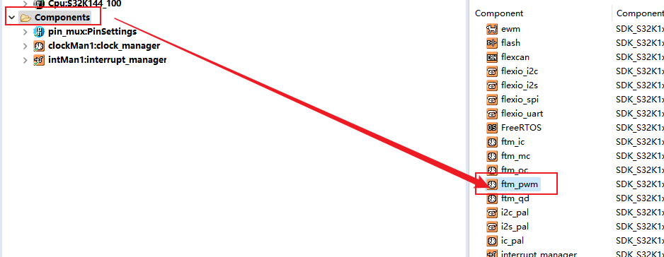
1.1进入PWM外设配置界面
双击Components >> 双击 ftm_pwm(灵活定时器模块–脉宽调制)
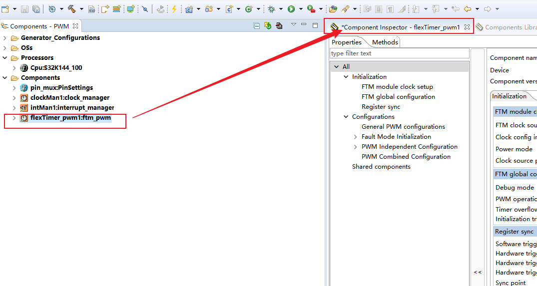
1.2进入配置界面
双击新出现的组件文件夹,进入配置界面
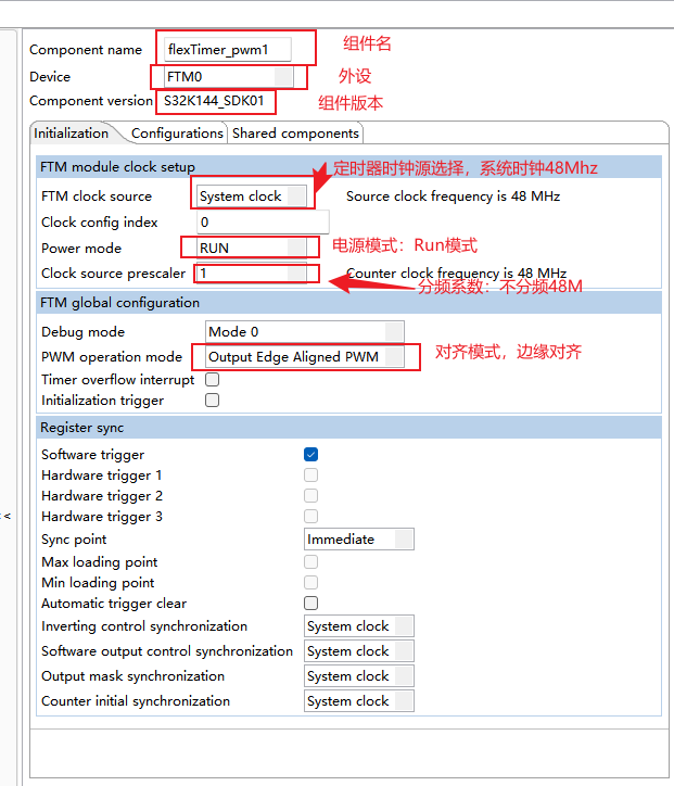
1.3部分配置选项介绍
1.3.1 定时器外设相关配置
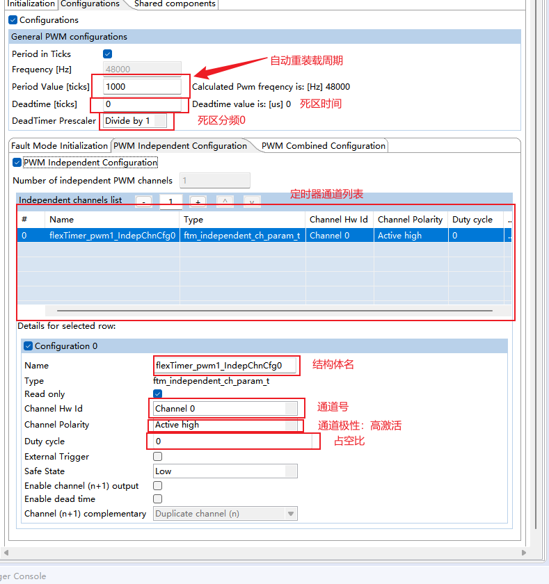
1.3.2 pwm相关配置介绍
2PWM小实验
本次实验使用FTM0的四个通道输出PWM波控制四路小灯
结合之前学习的adc和按键输入
实现调整滑动变阻器控制小灯的亮灭
通过按键调整PWM的占空比和频率
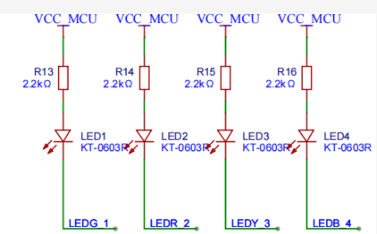
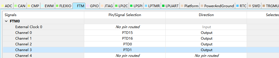
2.1硬件电路
FTM0_CH1-PTD16-LEDG_1,
FTM0_CH0-PTD15-LEDR_2,
FTM0_CH3-PTD1-LEDY_3,
FTM0_CH2-PTD0-LEDB_4


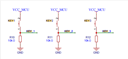
使用的按键
key1-PTC12,key2-PTC13

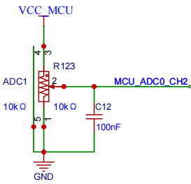
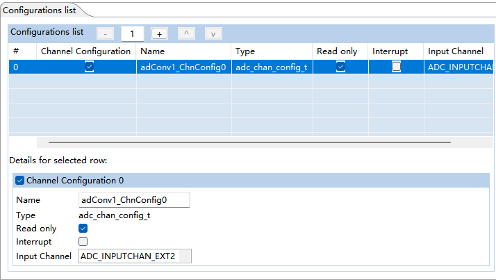
使用到的adc通道和变阻器
ADC0-CH2

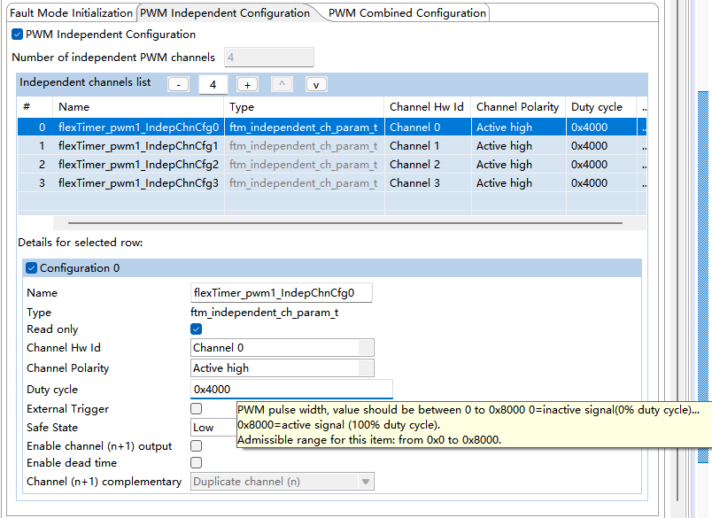
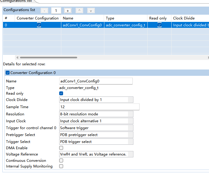
2.2pwm,ADC详细配置
通道极性高电平有效、占空比50%
adc配置
2.3pinmux配置及注意事项
若通道对应管脚已经被设置为其他功能如gpio,需恢复默认状态。
确认没有其他功能占用后,将io从新映射为定时器输出。
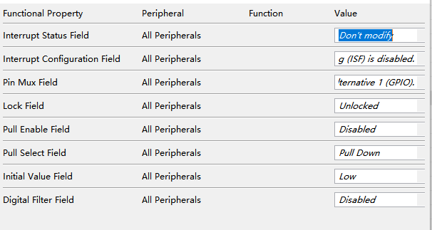
key——io配置

2.4 使用到的函数及参数介绍
(gpio和adc函数不在此赘述)
定时器外设初始化:
uint32_t instance:定时器实例即要使用的定时器
const ftm_user_config_t * info :定时器配置结构体
ftm_state_t *state:定时器结构体
status_t FTM_DRV_Init(uint32_t instance,const ftm_user_config_t * info, ftm_state_t *state);
PWM初始化:
uint32_t instance:pwm实例即要使用的定时器
const ftm_pwm_param_t * param:PWM配置结构体
status_t FTM_DRV_InitPwm(uint32_t instance,const ftm_pwm_param_t * param)
PWM通道更新函数:
uint32_t instance:pwm实例即要使用的定时器
uint8_t channel:需要更新的通道
ftm_pwm_update_option_t typeOfUpdate:通道变更类型
uint16_t firstEdge:占空比(第一翻转边沿)
uint16_t secondEdge:第二翻转边沿(用于中心对齐模式)
bool softwareTrigger:是否软件触发更新(true/flase)
status_t FTM_DRV_UpdatePwmChannel(uint32_t instance,uint8_t channel, ftm_pwm_update_option_t typeOfUpdate, uint16_t firstEdge,uint16_t secondEdge,bool softwareTrigger);
参数详解
参数 类型 说明
instance uint32_t FTM模块实例号,如 0 对应 FTM0,1 对应 FTM1。
typeOfUpdate ftm_pwm_update_option_t PWM对齐模式:
newValue uint32_t 新的PWM周期值:写入 FTMx_MOD 寄存器,决定PWM频率。
计算公式:
• 边沿对齐:PWM频率 = FTM时钟 / (newValue + 1)
• 中心对齐:PWM频率 = FTM时钟 / (2 * (newValue + 1))
softwareTrigger bool • true:立即更新周期值(写入 FTMx_MOD)
• false:等待硬件触发(如下一个计数器溢出)
status_t FTM_DRV_UpdatePwmPeriod(uint32_t instance,ftm_pwm_update_option_t typeOfUpdate,uint32_t newValue,bool softwareTrigger)
2.4具体代码
/* ###################################################################
**     Filename    : main.c
**     Processor   : S32K1xx
**     Abstract    :
**         Main module.
**         This module contains user's application code.
**     Settings    :
**     Contents    :
**         No public methods
**
** ###################################################################*/
/*!
** @file main.c
** @version 01.00
** @brief
**         Main module.
**         This module contains user's application code.
*/
/*!
**  @addtogroup main_module main module documentation
**  @{
*/
/* MODULE main */


/* Including necessary module. Cpu.h contains other modules needed for compiling.*/
#include "Cpu.h"

  volatile int exit_code = 0;

/* User includes (#include below this line is not maintained by Processor Expert) */
#include "delay.h"


#define ADC_VREFH   3.3f    // 最大参考电压
#define ADC_VREFL   0.0f    // 最小参考电压
float adcValue;             // 变阻器电压
uint16_t adcreval;          // 实际采样数值
uint16_t adcmax;            // 最大量程实际数值
// 定义按键引脚和掩码
#define KEY1_PIN_MASK    (1U << 12)  // PTC12
#define KEY2_PIN_MASK    (1U << 13)  // PTC13
#define DEBOUNCE_DELAY_MS 20         // 去抖动延时

// 按键检测函数(非阻塞式)
int Check_Keys(void) {
    static uint8_t key_pressed = 0; // 记录当前按下的按键(0:无, 1:KEY1, 2:KEY2)

    // 读取当前所有按键状态
    uint32_t pinState = PINS_DRV_ReadPins(PTC);

    // 检测 KEY1 (PTC12)
    if ((pinState & KEY1_PIN_MASK) && (key_pressed != 1)) {
        delay_ms(DEBOUNCE_DELAY_MS);
        if (PINS_DRV_ReadPins(PTC) & KEY1_PIN_MASK) {
            key_pressed = 1;
            return 1; // 返回 KEY1 按下
        }
    }

    // 检测 KEY2 (PTC13)
    if ((pinState & KEY2_PIN_MASK) && (key_pressed != 2)) {
        delay_ms(DEBOUNCE_DELAY_MS);
        if (PINS_DRV_ReadPins(PTC) & KEY2_PIN_MASK) {
            key_pressed = 2;
            return 2; // 返回 KEY2 按下
        }
    }

    // 检测按键释放
    if (!(pinState & (KEY1_PIN_MASK | KEY2_PIN_MASK))) {
        key_pressed = 0; // 重置状态
    }

    return 0; // 无按键按下
}

float read_adc_CH2(void)
{
    ADC_DRV_ConfigChan(INST_ADCONV1, 0, &adConv1_ChnConfig0);
    // 读取ADC2通道的值
    ADC_DRV_WaitConvDone(INST_ADCONV1);
    ADC_DRV_GetChanResult(INST_ADCONV1, 0, (uint16_t * const)&adcreval);
    adcValue = ((float)adcreval / adcmax) * (ADC_VREFH - ADC_VREFL); // 计算电压值
    return adcValue;
}


void FTM0_Dutycycle_Output(int chn, int value)  // 设置PWM占空比
{
	FTM_DRV_UpdatePwmChannel(INST_FLEXTIMER_PWM1,chn,FTM_PWM_UPDATE_IN_DUTY_CYCLE,value * 327.68,0,true);
}

  void FTM0_Period_Output(int tick) // 设置PWM周期
  {
	FTM_DRV_UpdatePwmPeriod(INST_FLEXTIMER_PWM1,FTM_PWM_UPDATE_IN_TICKS,tick,true);
}
/*!
  \brief The main function for the project.
  \details The startup initialization sequence is the following:
 * - startup asm routine
 * - main()
*/
int main(void)
{
  /* Write your local variable definition here */
  float adcValue1; // 变阻器电压
  int Duty_precent_adc;          // adc获得的要修改pwm占空百分比
  int Duty_precent_adc_last;      // 上次的pwm占空百分比
  int key_Duty = 0;
  int key_Period = 1000;
  int key_num; // 按键值
	int MCU_Freq;
	ftm_state_t ftmStateStruct1;
  /*** Processor Expert internal initialization. DON'T REMOVE THIS CODE!!! ***/
  #ifdef PEX_RTOS_INIT
    PEX_RTOS_INIT();                   /* Initialization of the selected RTOS. Macro is defined by the RTOS component. */
  #endif
  /*** End of Processor Expert internal initialization.                    ***/

  /* Write your code here */
  /* For example: for(;;) { } */
    //根据配置确定阈值
    if(adConv1_ConvConfig0.resolution == ADC_RESOLUTION_8BIT)
    {
        adcmax = (1 << 8);
    }
    else if(adConv1_ConvConfig0.resolution == ADC_RESOLUTION_10BIT)
    {
        adcmax = (1 << 10);
    }
    else if(adConv1_ConvConfig0.resolution == ADC_RESOLUTION_12BIT)
    {
        adcmax = (1 << 12);
    }
	CLOCK_SYS_Init(g_clockManConfigsArr, CLOCK_MANAGER_CONFIG_CNT,g_clockManCallbacksArr, CLOCK_MANAGER_CALLBACK_CNT);
	CLOCK_SYS_UpdateConfiguration(0U, CLOCK_MANAGER_POLICY_AGREEMENT);
	MCU_Freq = delay_init();//初始化delay函数

	FTM_DRV_Init(INST_FLEXTIMER_PWM1, &flexTimer_pwm1_InitConfig,&ftmStateStruct1); // 初始化FTM0
	FTM_DRV_InitPwm(INST_FLEXTIMER_PWM1, &flexTimer_pwm1_PwmConfig);  // 初始化PWM
  PINS_DRV_Init(NUM_OF_CONFIGURED_PINS, g_pin_mux_InitConfigArr); // 初始化引脚
  ADC_DRV_ConfigConverter(INST_ADCONV1, &adConv1_ConvConfig0);	//	配置ADC0
  ADC_DRV_AutoCalibration(INST_ADCONV1);	// 自校验

  while (1)
  {
          // 读取ADC2通道的值
      adcValue1 = read_adc_CH2();
          //放大浮点类型变为int型
      Duty_precent_adc  = (int)((adcValue1 / 3.3) * 100 + 0.5);

      if(Duty_precent_adc != Duty_precent_adc_last) // 如果当前值和上次值不一样,才更新pwm占空比
      {
          FTM0_Dutycycle_Output(0, Duty_precent_adc); // 更新pwm占空比
          FTM0_Dutycycle_Output(1, Duty_precent_adc); // 更新pwm占空比
          FTM0_Dutycycle_Output(2, Duty_precent_adc); // 更新pwm占空比
          FTM0_Dutycycle_Output(3, Duty_precent_adc); // 更新pwm占空比
          Duty_precent_adc_last = Duty_precent_adc; // 更新上次值
      }
      key_num = Check_Keys(); // 读取按键值
      if(key_num == 1) // 按键1按下
      {
        //百分比限制在0 - 100之间
          key_Duty += 10; // 增加10%
          if(key_Duty > 100)
          {
              key_Duty = 0;
          }
          FTM0_Dutycycle_Output(0, key_Duty); // 更新pwm占空比
          FTM0_Dutycycle_Output(1, key_Duty); // 更新pwm占空比
          FTM0_Dutycycle_Output(2, key_Duty); // 更新pwm占空比
          FTM0_Dutycycle_Output(3, key_Duty); // 更新pwm占空比
          key_num = 0; // 清除按键值
      }
      else if(key_num == 2) // 按键2按下
      {
          key_Period += 1000; // 增加10%
          if(key_Period > 10000)
          {
              key_Period = 0;
          }
          FTM0_Period_Output(key_Period); // 设置PWM周期
          key_num = 0; // 清除按键值
      }
  }


  /*** Don't write any code pass this line, or it will be deleted during code generation. ***/
  /*** RTOS startup code. Macro PEX_RTOS_START is defined by the RTOS component. DON'T MODIFY THIS CODE!!! ***/
  #ifdef PEX_RTOS_START
    PEX_RTOS_START();                  /* Startup of the selected RTOS. Macro is defined by the RTOS component. */
  #endif
  /*** End of RTOS startup code.  ***/
  /*** Processor Expert end of main routine. DON'T MODIFY THIS CODE!!! ***/
  for(;;) {
    if(exit_code != 0) {
      break;
    }
  }
  return exit_code;
  /*** Processor Expert end of main routine. DON'T WRITE CODE BELOW!!! ***/
} /*** End of main routine. DO NOT MODIFY THIS TEXT!!! ***/

void SysTick_Handler(void) {

}
/* END main */
/*!
** @}
*/
/*
** ###################################################################
**
**     This file was created by Processor Expert 10.1 [05.21]
**     for the NXP S32K series of microcontrollers.
**
** ###################################################################
*/


 1426
1426

 被折叠的 条评论
为什么被折叠?
被折叠的 条评论
为什么被折叠?
 到【灌水乐园】发言


