


1.多路选择器
module MUX41a(a,b,c,d,s1,s0,y);
	input a,b,c,d;
	input s1,s0;
	output y;
	reg y;
	always @(a or b or c or d or s1 or s0)
	begin : MUX41
		case({s1,s0})
			2'b00 : y<=a;
			2'b01 : y<=b;
			2'b10 : y<=c;
			2'b11 : y<=d;
			default : y<=a;
		endcase
	end

endmodule
2.4X4路交叉开关
module jiaochakaiguan
(
  IN0,
  IN1,
  IN2,
  IN3,
  SEL0,
  SEL1,
  SEL2,
  SEL3,
  OUT0,
  OUT1,
);
  parameter WL = 16;
  input [WL-1 : 0] IN0, IN1, IN2, IN3;
  input SEL1, SEL0, SEL2, SEL3;
  output [WL-1 : 0] OUT0, OUT1;

  reg [WL-1 : 0] OUT0, OUT1;

  always @ (IN0 or IN1 or IN2 or IN3 or SEL0 or SEL1)
  begin
    case ({SEL0, SEL1})
	   2'b00 : OUT0 = IN0;
		2'b01 : OUT0 = IN1;
		2'b10 : OUT0 = IN2;
		2'b11 : OUT0 = IN3;
	 endcase
  end

  always @ (IN0 or IN1 or IN2 or IN3 or SEL2 or SEL3)
  begin
    case ({SEL2, SEL3})
	   2'b00 : OUT1 = IN0;
		2'b01 : OUT1 = IN1;
		2'b10 : OUT1 = IN2;
		2'b11 : OUT1 = IN3;
	 endcase
  end
endmodule
3.8输入的优先编码器
// module top, 4 input priority encoder with zero input check
module ecoder(
  IN        ,   // input
  OUT       );  // output
input [7:0] IN;
output[2:0] OUT;

reg   [2:0] OUT;
// get the OUT
always @ (IN) begin
   if(IN[7])       // 第一优先
     OUT = 3'b111;
   else if(IN[6])  // 第二优先
     OUT = 3'b110;
   else if(IN[5])  // 第三优先
     OUT = 3'b101;
   else if(IN[4])  // 第四优先
     OUT = 3'b100;
   else if(IN[3])  // 第第五优先
     OUT = 3'b011;
	else if(IN[2])  // 第六优先
     OUT = 3'b010;
	else if(IN[1])  // 第七优先
     OUT = 3'b001;
	else if(IN[0])  // 第八优先
     OUT = 3'b000;
end
endmodule
4.4-16的译码器
// module top, 4 input priority encoder with zero input check
module ecoder(
  IN        ,   // input
  OUT       );  // output

input [3:0] IN;
output[15:0] OUT;

reg   [15:0] OUT;
// get the OUT
always @ (IN) begin
  case(IN)
    4'b0000: OUT = 16'b0000_0000_0000_0001;
    4'b0001: OUT = 16'b0000_0000_0000_0010;
	  4'b0010: OUT = 16'b0000_0000_0000_0100;
	   4'b0011: OUT = 16'b0000_0000_0000_1000;
		 4'b0100: OUT = 16'b0000_0000_0001_0000;
		  4'b0101: OUT = 16'b0000_0000_0010_0000;
		   4'b0110: OUT = 16'b0000_0000_0100_0000;
			4'b0111: OUT = 16'b0000_0000_1000_0000;
			 4'b1000: OUT = 16'b0000_0001_0000_0000;
			  4'b1001: OUT = 16'b0000_0010_0000_0000;
			   4'b1010: OUT = 16'b0000_0100_0000_0000;
				 4'b1011: OUT = 16'b0000_1000_0000_0000;
				  4'b1100: OUT = 16'b0001_0000_0000_0000;
				   4'b1101: OUT = 16'b0010_0000_0000_0000;
					 4'b1110: OUT = 16'b0100_0000_0000_0000;
					  4'b1111: OUT = 16'b1000_0000_0000_0000;


    //  full case 不需要写default,否则一定要有default
  endcase
end
endmodule
5.无符号加法器
module top(
  IN1   ,
  IN2   ,
  OUT   );
input[3:0] IN1, IN2;
output[4:0] OUT;
reg[4:0] OUT;
always@(IN1 or IN2) begin // 生成组合逻辑的always 块
  OUT = IN1 + IN2;
end
endmodule
6.补码加法器
module bumaaad(
IN1,
IN2,
OUT
);
input signed [3:0] IN1,IN2;
output signed [4:0] OUT;
reg signed [4:0] OUT;
always@(IN1 or IN2) begin
   OUT=IN1+IN2;
end
endmodule
7.带两级流水线的加法器
module wateradd(
IN1,
IN2,
CLK,
OUT
);
input [8:0] IN1,IN2;
input CLK;
output [4:0] OUT;
reg [3:0] in1_d1R,in2_d1R,in3_d1R,in4_d1R;
reg [4:0] addr_out ,OUT;
always@(posedge CLK) begin
	 in1_d1R<=IN1;
	  in2_d1R=IN2;
end
always@(posedge CLK) begin
	in3_d1R<=in1_d1R;
	in4_d1R<=in2_d1R;
	OUT    <=addr_out;
end
always@(in1_d1R or in2_d1R)begin
   addr_out=in3_d1R+in4_d1R;
end
endmodule
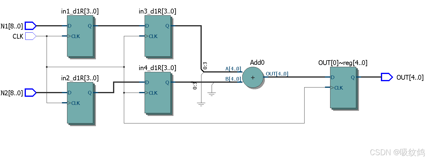
8.两级流水线加法器RTL结构图
9.无符号乘法器
module usignmux(
IN1,
IN2,
OUT
);
input[3:0] IN1,IN2;
output[4:0] OUT;
reg [4:0] OUT;
always@(IN1 or IN2) begin
   OUT=IN1+IN2;
end
endmodule
10.有符号乘法器
module mux(
IN1,
IN2,
OUT
);
input signed[3:0] IN1,IN2;
output signed[7:0] OUT;
reg signed[7:0] OUT;
always@ (IN1 or IN2)begin
 OUT=IN1*IN2;
 end
 endmodule
11.输入和输出都带有流水线的无符号乘法器
module mux(
IN1,
IN2,
OUT,
CLK
);
input [3:0] IN1,IN2;
input CLK;
output [7:0] OUT;
reg [3:0] in1_d1R,in2_d1R;
reg [7:0] mux_out,OUT;
always@ (posedge CLK)begin
in1_d1R <= IN1;
in2_d1R <= IN2;
OUT <= mux_out;
 end
always@ (IN1 or IN2)begin
 mux_out=in1_d1R*in2_d1R;
 end
 endmodule
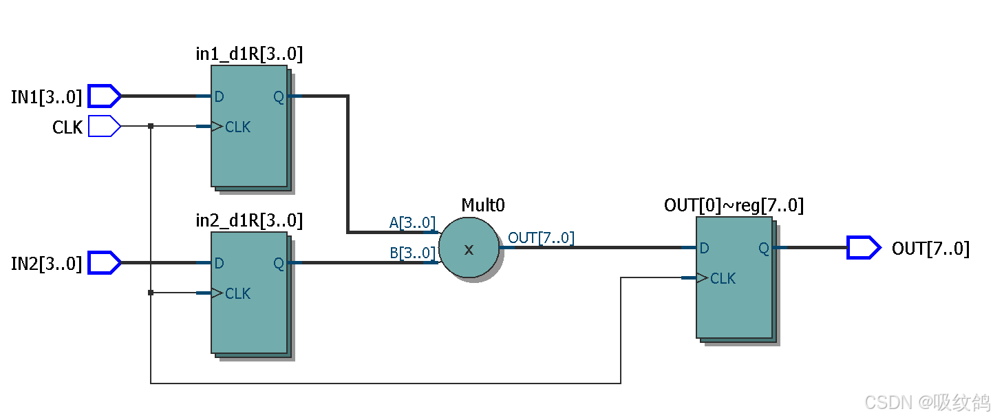
RTL视图如下
12.有符号的8位乘法器
//8wei mul
module chengfaqi
(
  IN1,
  IN2,
  OUT
);
  input signed [7 : 0] IN1, IN2;
  output signed [15 : 0] OUT;

  reg signed [15 : 0] OUT;

  always @ (IN1 or IN2)
    begin
      OUT = IN1 * IN2;
    end
endmodule
13.有流水线的8位乘法器
//8wei D mul
module chengfaqi
(
  IN1,
  IN2,
  CLK,
  OUT
);
  input signed [7 : 0] IN1, IN2;
  input CLK;
  output signed [15 : 0] OUT;

  reg signed [15 : 0] OUT, mul_out;
  reg signed [7 : 0] in1_d1R, in2_d1R;

  always @ (posedge CLK)
    begin
      in1_d1R <= IN1;
      in2_d1R <= IN2;
      OUT     <= mul_out;
    end
  always @ (in1_d1R or in2_d1R)
    begin
      mul_out = in1_d1R * in2_d1R;
    end
endmodule
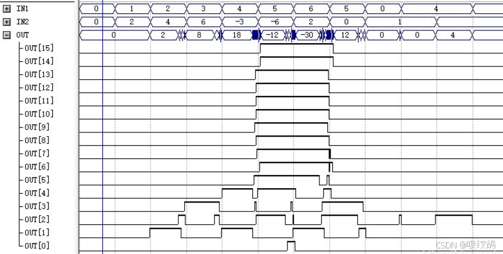
仿真结果
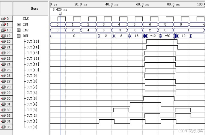
通过比较八位带D触发器与不带D触发器的波形仿真图,可以观察到毛刺减少。
14.计数器
设计复杂的计数器,带有多种信号,其中同步清零CLR的优先级最高,使能EN次之,LOAD最低
module cnt(
RST,
CLK,
EN,
CLR,
LOAD,
DATA,
CNTVAL,
OV
);
input RST,CLK ,EN,CLR,LOAD ;
input [3:0] DATA ;
output [3:0]CNTVAL;
output OV;
reg [3:0] CNTVAL,cnt_next;
reg OV;
parameter CNT_MAX_VAL=9;

always @(EN or CLR or LOAD or DATA or CNTVAL)begin
    if(CLR) begin // 清零有效
	  cnt_next = 0;
	 end
	  else begin //清零无效
	  if(EN) begin  // 使能有效
		if(CNTVAL < CNT_MAX_VAL) begin // 未计数到最大值, 下一值加1
          cnt_next = CNTVAL + 1'b1;
			 end
         else begin // 计数到最大值,下一计数值为0
          cnt_next = 0;
        end
		end
		else begin  //使能无效
		  if(LOAD) begin // 加载有效
				cnt_next = DATA;
		  end
		 else begin
		      cnt_next=CNTVAL;
		 end
	  end
	 end
end


 always @ (posedge CLK or posedge RST )begin
    if(RST )
		CNTVAL<=0;
	 else
		CNTVAL<=cnt_next;
end

 always @ (CNTVAL)begin
    if(CNTVAL==CNT_MAX_VAL)
			OV = 1;
	 else
			OV = 0;
end

endmodule
- 设计一个最简单的计数器,只有一个CLK输入和一个OVerflow输出,当计数到最大值的时钟周期CLK输出1,代码如下
-
module cnt(
CLK,
OVerflow
);

input CLK;
output OVerflow=0;
reg OVerflow;
reg [3:0] cnt_next=0;
parameter CNT_MAX_VAL = 9;
always @(posedge CLK)begin
if(cnt_next<CNT_MAX_VAL-1)begin
cnt_next<=cnt_next+1'b1;
end
else begin
OVerflow<=1;
cnt_next<=0;
end
end
endmodule
15.状态机
-
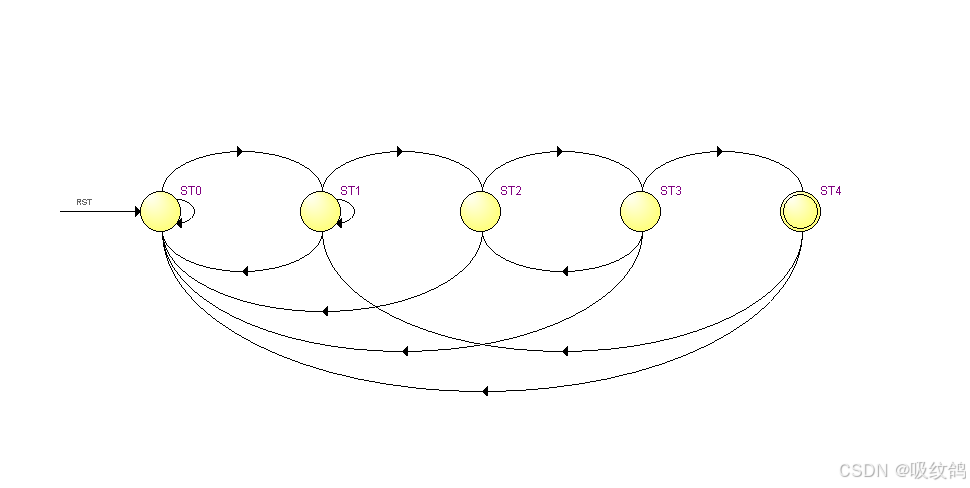
设计一个用于识别2进制序列“1011”的状态机
- 基本要求:
- 电路每个时钟周期输入1比特数据,当捕获到1011的时钟周期,电路输出1,否则输出0
- 使用序列101011010作为输出的测试序列
- 扩展要求:
- 给你的电路添加输入使能端口,只有输入使能EN为1的时钟周期,才从输入的数据端口向内部获取1比特序列数据。
-
module ztj(
CLK ,
RST ,
IN  ,
EN  ,
OUT ,
);

input CLK ;
input RST ;
input EN ;
input IN;
output OUT;

parameter ST0=0;
parameter ST1=1;
parameter ST2=2;
parameter ST3=3;
parameter ST4=4;

reg [2:0]stateR;
reg [2:0]next_state;
reg OUT;

always @(IN or EN or stateR) begin
    case (stateR)
		ST0: begin
			if(EN==1&&IN==1) next_state=ST1;
			else
			next_state=ST0;
		end
		ST1:begin
			if(EN==1&&IN==0) next_state=ST2;
			else if(EN==1&&IN==1) next_state=ST1;
			else next_state=ST0;
		end
		ST2:begin
			if(EN==1&&IN==1) next_state=ST3;
			else next_state=ST0;
		end
		ST3:begin
			if(EN==1&&IN==1) next_state=ST4;
			else if(EN==1&&IN==0) next_state=ST2;
			else next_state=ST0;
			end
		ST4:begin
			if(EN==1&&IN==1) next_state=ST1;
			else next_state=ST0;
			end
    endcase
end


always @(stateR)begin
if(stateR==ST4)
OUT=1'b1;
else
OUT=1'b0;
end


always @(posedge CLK or posedge RST)begin
if(RST)
stateR<=ST0;
else
 stateR<= next_state;
 end
 endmodule
RTL中的状态转移图
-
16.带加载使能和移位使能的并入串出”的移位寄存器
-
module sr(
RST,
CLK,
LOAD,
EN,
IN,
OUT
);
input RST,CLK,EN,LOAD;
input [3:0]IN;
output OUT;
reg [3:0] shift_R;
reg OUT;
always @ (posedge CLK or posedge RST or posedge LOAD)begin
if(RST)
shift_R <=0;
else begin
    if(LOAD)begin
		shift_R[3:0] <= IN[3:0];
	end
else begin
    if(EN) begin
	shift_R[3:1] <= shift_R[2:0];
	shift_R[0] <= 0;
	OUT =  shift_R[3];
	end
else begin
	shift_R[3:0]<=shift_R[3:0];
	   end
    end
  end
end
endmodule
双口RAM
module dpram
(
  WE,
  WCLK,
  RCLK,
  WA,
  RA,
  WD,
  RD
);
  parameter DATAWL = 0;
  parameter ADDRWL = 0;
  parameter C2Q    = 0;

  input                 WE, WCLK, RCLK;
  input  [ADDRWL-1 : 0] WA, RA;
  input  [DATAWL-1 : 0] WD;
  output [DATAWL-1 : 0] RD;

  reg [DATAWL-1 : 0] RD;
  reg [DATAWL-1 : 0] mem [(1<<ADDRWL)-1 : 0]; ///????

  always @ (posedge WCLK)
  begin
    if(WE)
	   mem[WA] <= #C2Q WD;//????
  end

  always @ (posedge RCLK)
  begin
    RD <= #C2Q mem[RA];
  end

// ######################################
// synopsys translate_off
// ######################################
// the code below this line will NOT take part into synthesis
// they are only needed by RTL simulation
  // task DumpDpRAM, get the content of RAM[addr]

  task DumpDpRAM;
  input [ADDRWL-1 : 0] addr;
  input [DATAWL-1 : 0] content;
  begin
    content = mem[addr];
  end
  endtask

  task RAMInit;
  integer i;
  reg [DATAWL-1 : 0] initData;
  begin
    initData = ‘hAAAA;
	 //initData = (1<<DATAWL) - 1;
	 for(i = 0; i << (1 << ADDRWL); i = i + 1)
	   mem[i] = initData;
  end
  endtask

  initial
  begin
    RAMInit();
	 $display("module dpram().RAMInit()called @ %0d", $time);
  end
// ######################################
// synopsys translate_on
// ######################################
// the code below this line will take part in synthesis
endmodule
17.ROM
module ROM
(
  CLK,
  RA,
  RD
);

  input CLK;
  input [6 : 0] RA;
  output [12 : 0] RD;
  reg [12 : 0] RD;
  always @ (posedge CLK)
    case(RA)
	   7'd0 : RD = #1 13'd 0;
		7'd1 : RD = #1 13'd 101;
		7'd2 : RD = #1 13'd 201;
		7'd3 : RD = #1 13'd 301;
		... ... ...
		7'd127 : RD = #1 13'd 8190;
	 endcase
endmodule
18.寄存器组和多重例化
// module top, example for, 'for' and 'generate'
module top(
  CLK   ,
  RST   ,
  IN1   ,
  OUT1  );
parameter DWL = 8;
parameter reg_len = 3;
input CLK;
input RST;
input  [DWL-1:0] IN1;
output [DWL-1:0] OUT1;

reg  [DWL-1:0] in1R[reg_len-1:0];
wire [DWL-1:0] in1R_inW[reg_len-1:0];
integer idx;
always @ (posedge CLK or posedge RST) begin
  if(RST) begin
    for(idx = 0; idx < reg_len; idx = idx +1) begin
      in1R[idx] <= 0;
    end
  end
  else begin
    for(idx = 0; idx < reg_len; idx = idx +1) begin
      in1R[idx] <= in1R_inW[idx];
    end
  end
end

genvar i_g;
generate
for (i_g =0; i_g < reg_len; i_g=i_g+1) begin: MULT_INST
  wire [DWL-1:0] logic_inW;
  if(i_g == 0) begin
    assign logic_inW = IN1;
  end
  else begin
    assign logic_inW = in1R[i_g-1];
  end
  param_logic U_pl(
    .IN    (logic_inW      ),
    .OUT   (in1R_inW[i_g] ));
  defparam U_pl.DWL     = DWL;
  defparam U_pl.INST_P1 = i_g;
end
endgenerate
assign OUT1 = in1R[reg_len-1];
endmodule

module param_logic(
  IN    ,
  OUT   );
parameter DWL     = 0;
parameter INST_P1 = 0;
input  [DWL-1:0] IN  ;
output [DWL-1:0] OUT ;
assign OUT = IN + INST_P1;
endmodule
作者水平有限,如有错误请在评论区指出。


 1393
1393

 被折叠的 条评论
为什么被折叠?
被折叠的 条评论
为什么被折叠?
 到【灌水乐园】发言


