


 本文详细描述了在华为网络环境中配置Spine-1、Leaf-1A和Leaf-1B的IP地址、OSPF路由以及VXLAN的基本配置过程,包括接口设置、VNI配置和业务接入点,最后通过展示验证命令确认配置成功。
文章目录
组网和配置思路
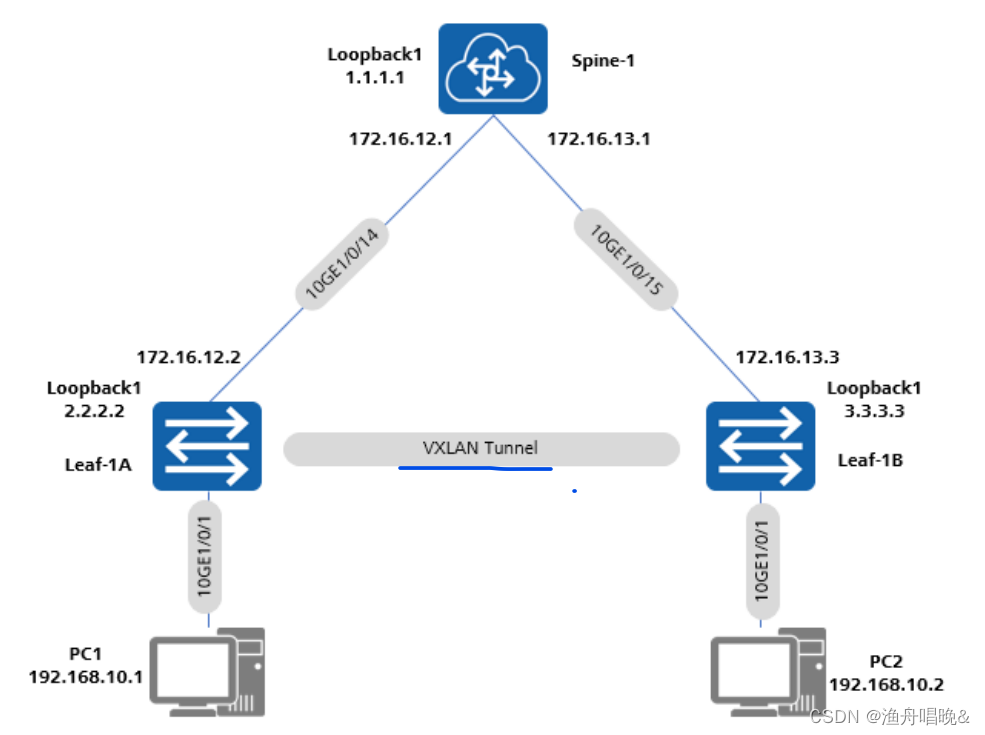
配置 Spine-1,Leaf-1 和 Leaf-2 的IP 地址
<HUAWEI>system-view immediately
[HUAWEI] sysname Spine-l
[Spine-1]interface LoopBack1
[Spine-1-LoopBackl]ip address 1.1.1.1 32
[Spine-1-LoopBack1]quit
[Spine-1]interface 10GE 1/0/14
[Spine-1-10GE1/0/14]undo portswitch
[Spine-1-10GE1/0/14]ip address 172.16.12.1 24
Spine-1-10GE1/0/14]quit
[Spine-1]interface 10GE 1/0/15
[Spine-1-10GE1/0/15]undo portswitch
[Spine-1-10GE1/0/15]ip address 172.16.13.1 24
[Spine-1-10GE1/0/15]quit

<HUAWEI>system-view immediately
HUAWEI]sysname Leaf-1A
Leaf-1A]interface LoopBack 1
[Leaf-1A-LoopBack1]ip address 2.2.2.2 32
[Leaf-1A-LoopBackl]quit
[Ieaf-1A]interface 10
[Leaf-1A]interface 10GE 1/0/14
Leaf-1A-10GE1/0/14]undo portswitch
[Leaf-1A-10GE1/0/14]ip address 172.12.12.2 24
[Leaf-1A-10GE1/0/14]quit

<HUAWEI>system-view immediately
HUAWEI]sysname Leaf-1B
[Leaf-1B] interface LoopBack 1
[Leaf-1B-LoopBackl]ip address 3.3.3.3 32
[Leaf-1B-LoopBack1]quit
[Leaf-1B]interface 10GE 1/0/15
[Leaf-1B-10GE1/0/15]undo portswitch
[Leaf-1B-10GE1/0/15]ip address 172.16.13.2 24
[Leaf-1B-10GE1/0/15]quit
配置OSPF
Leaf-1A、Leaf-1B 分别配置环回口 LoopBack1,作为VTEP IP,通告进入底层路由协议。
immediately<Spine-1>system-view
[Spine-1]ospf 1
[Spine-1-ospf-1]area 0
[Spine-1-ospf-1-area-0.0.0.0]network 1.1.1.1 0.0.0.0
[Spine-1-ospf-1-area-0.0.0.0]network 172.16.12.0 0.0.0.255
[Spine-1-ospf-1-area-0.0.0.0]network 172.16.13.0 0.0.0.255
[Spine-1-ospf-1-area-0.0.0.0]return

<Leaf-1A>system-viewimmediately[Leaf-1A]ospf 1
[Leaf-1A-ospf-l]area 0
[Leaf-1A-ospf-1-area-0.0.0.0]net
[Leaf-1A-ospf-1-area-0.0.0.0]network 2.2.2.2 0.0.0.0
[Leaf-1A-ospf-1-area-0.0.0.0]network 172.16.12.0 0.0.0.255
[Leaf-1A-ospf-1-area-0.0.0.0]return

<Leaf-1B>system-viewimmediately
[Leaf-1B]ospf 1
[Leaf-1B-ospf-1]area 0
[Leaf-1B-ospf-1-area-0.0.0.0]network 3.3.3.3 0.0.0.0
[Leaf-1B-ospf-1-area-0.0.0.0]network 172.16.13.0 0.0.0.255
[Leaf-1B-ospf-1-area-0.0.0.0]return
配置 Leaf-1A 和 Leaf-1B 的 VXLAN 基本配置
[Leaf-1A]bridge-domain 10
[Leaf-1A-bd10]vxlan vni 5000
[Leaf-1A-bd10]quit
[Leaf-1A]interface Nve 1
[Leaf-1A-Nvel]source 2.2.2.2
[Leaf-1A-Nvel]vni 5000 head-end peer-list 3.3.3.3
[Leaf-1A-Nvel]quit

[Leaf-1B]bridge-domain 10
[Leaf-1B-bd10]vxlan vni 5000
[Leaf-1B-bd10]quit
[Leaf-1B]interface Nve 1
[Leaf-1B-Nve1]sourc 3.3.3.3
[Leaf-1B-Nvel]vni 5000 head-endpeer-list 2.2.2.2
[Leaf-1B-Nve1]quit
配置eaf-1A 和 Leaf-1B 的业务接入点
[Leaf-1A] interface 10ge 1/0/1.1 mode 12
[Leaf-1A-10GE1/0/1.1]encapsulation dotlq vid 10
[Leaf-1A-10GE1/0/1.1]bridge-domain 10
[Leaf-1A-10GE1/0/1.1]quit

[Leaf-1B] interface 10ge 1/0/1.1 mode 12
[Leaf-1B-10GE1/0/1.1] encapsulation dotlq vid 10
[Leaf-1B-10GE1/0/1.1]bridge-domain 10
[Leaf-1B-10GE1/0/1.1]quit
验证配置结果
执行 display vxlan tunnel 命令可查看到 VXLAN 隧道的信息,以Spine-1_显示为例。
<Leaf-1A>display vxlan vniNumber of vxlan vni
VNI		BD-ID		State
-----------------------------------
5000	10			up
<Leaf-1A>display vxlan tunnel
Number of vxlan Tunnel ID : 1
Tunnel ID	Source		Destination	State 	Type 	Uptime
4026531841	2.2.2.2		3.3.3.3		up		static	00:19:21
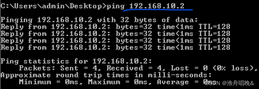
通过命令 Ping 来测试网络连通性,以 PC1 Ping PC2 为例:


 1420
1420

 被折叠的 条评论
为什么被折叠?
被折叠的 条评论
为什么被折叠?
 到【灌水乐园】发言


