


1.几个基本概念
TLP(Transaction Layer Packet): TLP包是由PCIe的Endpoint或者Root Complex发送的数据包。在PCIe体系中的事务层生成;TLP包由头(Hander)、数据(Data)、ECRC(校验)几个部分组成。TLP是用户程序和PCIe设备交互的唯一渠道.。
CDM:Configuration Dependent Module.This is an internal block in the native controller that has the PCIe configuration registers and some user-accessible registers.包括 PCIE配置寄存器和 厂家定义的寄存器(比如ATU和DMA等)。
ELBI:External Local Bus Interface.Delivers an inbound register RD/WR received by the controller to external application registers when the controller is expected to generate the PCIe completion of this register
RD/WR. For switch applications: the ELBI is intended for incoming requests that are targeted to local switch application registers, while TRGT1 is intended for TLPs that are passing through the switch. The controller automatically generates completions for requests that are routed to the ELBI。ELBI可以理解为通过PCIE访问一个CPU的内部空间寄存器。ELBI 主要是在EP端,使用RC没有该部分功能。
LBC:Local Bus Controller .This is an internal block that allows the DBI interface (from your application side), or the wire side interface (through the TRGT0 interface), to access the CDM or your external application registers on the ELBI.本地的寄存器控制,比如RC中断清除等相关都需要操作。
XALI:Transmit Client Interface.理解为给外部传输的接口
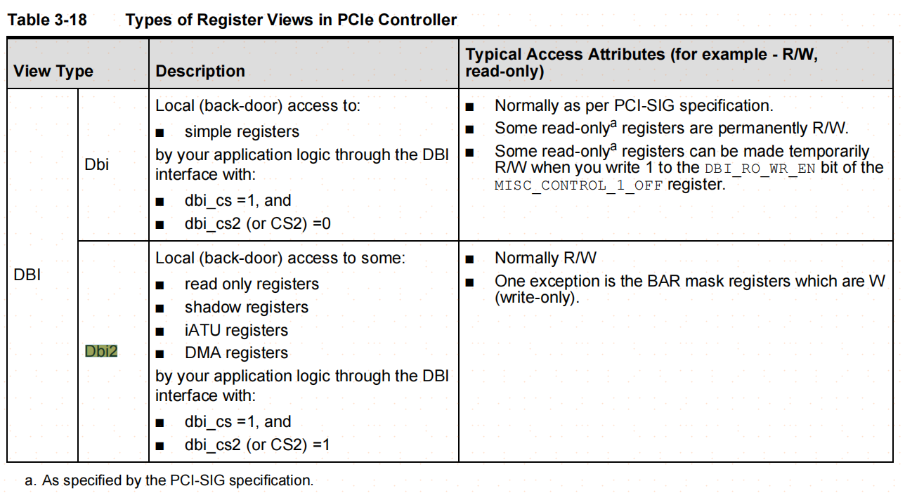
DBI:Data Bus Interface.You can use this interface to locally access the controller’s internal registers in the CDM, or your external application registers on the ELBI. You can optionally connect a local CPU or controller to this port.
ATU:Address Translation Unit ATU是一个地址转换单元,负责将一段存储器域的地址转换到PCIe总线域地址。
TLP中的地址哪里来?ATU转换过来的。ATU是一个地址转换单元,负责将一段存储器域的地址转换到PCIe总线域地址,除了地址转换外,还能提供访问类型等信息,这些信息都是ATU根据总线上的信号自己做的,数据都打包到TLP中,不用软件参与。
软件需要做的是配置ATU,所以如果ATU配置完成,并且能正常工作,那么CPU访问PCIe空间就和访问本地存储器空间方法是一样的,只要读写即可。
iATU mapping directions:
iATU can do inbound and outbound mapping.
Inbound mapping is PCI address to internal address.
Outbound mapping is internal address to PCI address.
iATU mapping modes:
On device, iATU supports two mapping modes, address match mode and BAR match mode.
For address match mode:
PCI address ------mapping------- internal address
For BAR match mode:
BAR number ------mapping------ internal address
Generally speaking, if your card has SoC, the FW on the SoC will configure the iATU mapping with BAR match mode. And don't let host side driver to configure it.
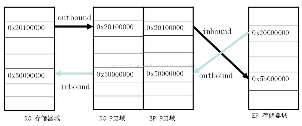
inbound/outbound
Inbound:PCI域訪问存储器域
Outbound:存储器域訪问PCI域
RC訪问EP: RC存储器域->outbound->RC PCI域->EP PCI域->inbound->EP存储器域
EP訪问RC:EP存储器域->outbound->EP PCI域->RC PCI域->inbound->RC存储器域
Out即出去,发起訪问的一側,须要进行outbound,去訪问对端
In即进来,被訪问的一側,须要进行inbound,使得对端能够訪问
EP訪问RC演示样例(蓝色箭头):
(1)首先,EP须要配置outbound,RC须要inbound(一般RC端不用配),这样就建立了EP端0x20000000到RC端0x50000000的映射
(2)在RC端改动0x50000000的内容,EP端能够看到对应的变化。从EP端读/写0x20000000和从RC端读/写0x50000000,结果是一样的
RC訪问EP演示样例(黑色箭头):
(1)首先,RC端须要配置outbound(一般内核中配好),EP端须要inbound(0x5b000000 inbound到BAR2),这样就建立了RC端0x20100000(BAR2)到EP端0x5b000000的映射
(2)在EP端改动0x5b000000内存的内容,在RC端0x20100000能够看到对应的变化,从RC端读/写0x20100000和从EP端读/写0x5b000000,结果是一样的

2.DWC PCIE Register
根据文档<DWC_pcie_ctl_rc_databook.pdf>、<DWC_pcie_ctl_rc_registers.pdf>,寄存器的分布图如下所示:
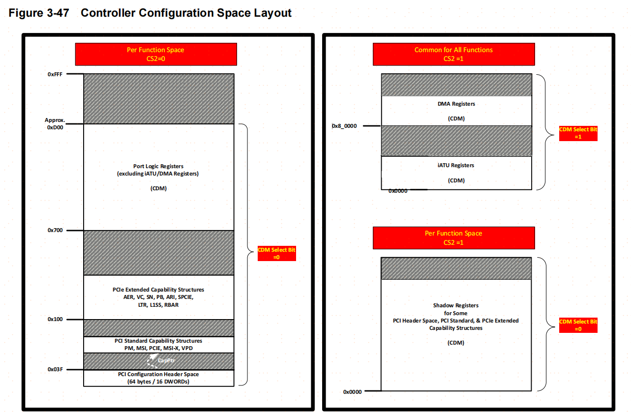
DBI内部划分了2个部分,DBI和DBI2通过片选(CS2)来进行选择。
When you are using an AXI DBI slave, shadow registers can only be accessed through the DBI where you select between the two registers using the CS2 address bit.This is called DBI2, CS2, dbi_cs2, DBI_CS2, or Dbi2 access; all of these terms mean the same thing.
上图左边是DBI访问空间内容, 右边是DBI2访问的空间内容。DBI2可以访问特殊的Shadow寄存器(IP厂家定制寄存器)。
使用AXI方式访问Slave DBI有两种方式,分别为专用方式(AXI Dedicated DBI Slave Access)和共享方式(AXI Shared DBI Slave Access)。
其中,专用方式可以直接通过DBI Slave通道访问DBI总线,进而访问CDM空间:
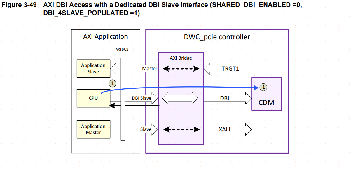
共享方式没有专用的DBI通道,,是和XALI访问共享一个通道(CPU作RC主模式时对内部的LBC控制寄存器的访问和对外部EP设备的寄存器访问使用的是同一套总线,并没有使用专用的DBI总线),两者通过一个Switch开关进行切换;
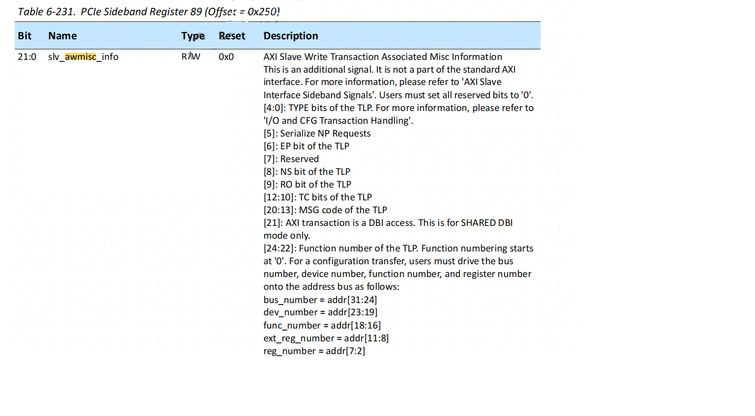
当配置开关slv_armisc_info[21]和slv_awmisc_info[21] =1时,开关切换到DBI通道,此时可以访问到CDM空间;否则将通过outbound方式访问XALI空间。
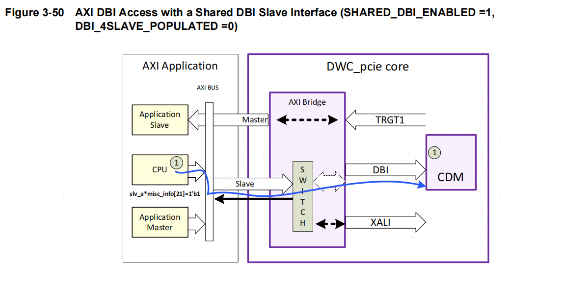
具体实现时,可以通过设置PCIE的SIDEBAND的2个寄存器slv_armisc_info/slv_awmisc_info来切换,保证从AXI接口访问访问到LBC。
3.CDM空间-配置寄存器
<DWC_pcie_ctl_rc_registers.pdf>文档描述了CDM空间的寄存器分布,如下图:
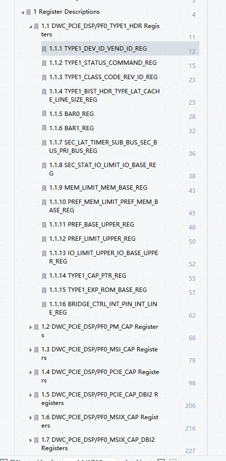
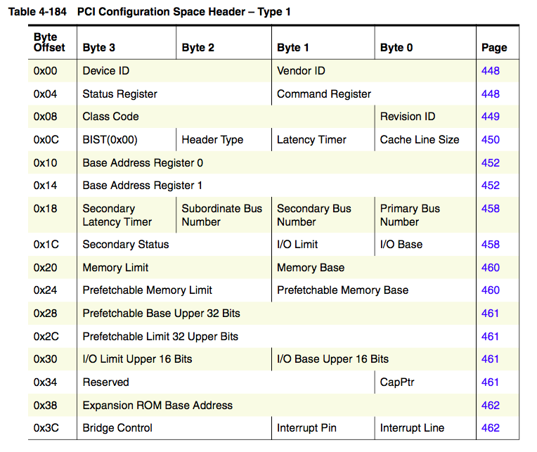
第一章DWC_PCIE_DSP/PF0_TYPE1_HDR Registers对应了PCIE协议中的配置空间寄存器:
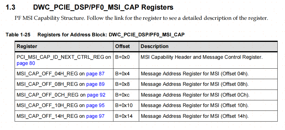
第二章开始文档开始描述CAP 寄存器,即对应功能的Capability(能力)说明,对应的寻址方式都是B+0x**:
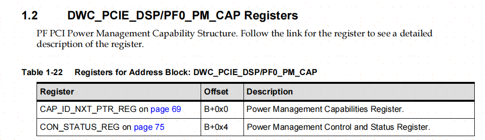
那么每个CAP结构的基地址B从哪里获得?
PCI-X 和PCIe 总线规范要求其设备必须支持Capabilities 结构。在PCI 总线的基本配置空间中,包含一个Capabilities Pointer 寄存器,该寄存器存放Capabilities 结构链表的头指针。在一个PCIe 设备中,可能含有多个Capability 结构,这些寄存器组成一个链表,如下图所示:
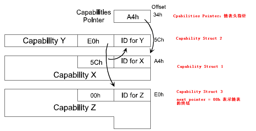
其中每一个Capability 结构都有唯一的ID 号,每一个Capability 寄存器都有一个指针,这个指针指向下一个Capability 结构,从而组成一个单向链表结构,这个链表的最后一个Capability 结构的指针为0。链表开始的指针地址为0x34处的1byte数值,以以imx6q为例,寻址过程如下:
1FF_C034 :00000040 所属内容 PF0_TYPE1_HDR :NEXT=0X40
1FF_C040: 5bc35001 所属内容 PF0_PM_CAP ID=0X01 NEXT=0X50
1FF_C050 :038a7005 所属内容 PCI_MSI_CAP
 最低0.47元/天 解锁文章


 658
658

 被折叠的 条评论
为什么被折叠?
被折叠的 条评论
为什么被折叠?
 到【灌水乐园】发言


