


autoware.universe源码略读2.2--localization:gyro_odometer/initial_pose_button_panel/error_monitor
gyro_odometer
Overview
这个包的目的是gyro_odometer is the package to estimate twist by combining imu and vehicle speed这里我觉得可以这么理解,vehicle speed就是指车辆的速度(默认向前),然后用IMU的陀螺仪来对角速度进行处理,这样就可以得到车辆的速度和行驶方向了,对应到twist里应该就是线速度和角速度就是了。
gyro_odometer_node
和EKF是一样的,节点里只是对GyroOdometer类进行了一个实例化的过程,具体的操作都在这个类里
gyro_odometer_core
这里就是定义了这个模块的主体类了,这里订阅的包括车辆的运动信息vehicle/twist_with_covariance以及IMU信息imu,对应着两个回调函数
  vehicle_twist_with_cov_sub_ = create_subscription<geometry_msgs::msg::TwistWithCovarianceStamped>(
    "vehicle/twist_with_covariance", rclcpp::QoS{100},
    std::bind(&GyroOdometer::callbackTwistWithCovariance, this, std::placeholders::_1));

  imu_sub_ = create_subscription<sensor_msgs::msg::Imu>(
    "imu", rclcpp::QoS{100}, std::bind(&GyroOdometer::callbackImu, this, std::placeholders::_1));
首先是void GyroOdometer::callbackTwistWithCovariance,这个函数很简单,只是接收了twist消息,同时这里也检查了IMU的数据是否有效,这里的判断标准就是看现在消息的时刻和最后的IMU消息的时间间隔是否在延迟允许之内
然后再来看callbackImu,这个函数从感官上讲是这个模块最长的。首先得到IMU到输出坐标系output_frame_ 的转换关系
  geometry_msgs::msg::TransformStamped::SharedPtr tf_imu2base_ptr =
    std::make_shared<geometry_msgs::msg::TransformStamped>();
  getTransform(output_frame_, imu_msg_ptr_->header.frame_id, tf_imu2base_ptr);
这里的output_frame_,在代码和参数文件里都是base_link
output_frame_(declare_parameter("base_link", "base_link"))
<arg name="output_frame" default="base_link" description="output frame id"/>
这里主要用的就是IMU的角速度,并且把这个角速度转换到base_link下了
  geometry_msgs::msg::Vector3Stamped angular_velocity;
  angular_velocity.header = imu_msg_ptr_->header;
  angular_velocity.vector = imu_msg_ptr_->angular_velocity;

  geometry_msgs::msg::Vector3Stamped transformed_angular_velocity;
  transformed_angular_velocity.header = tf_imu2base_ptr->header;
  tf2::doTransform(angular_velocity, transformed_angular_velocity, *tf_imu2base_ptr);
然后把这个转换后的角速度分别给geometry_msgs::msg::TwistStamped twist和geometry_msgs::msg::TwistWithCovarianceStamped twist_with_covariance,这里因为Y和Z轴的速度其实是没有观测的,所以策略是在给方差的时候给了个很大的值
最后一步相当于做了个很简单的零速修正,当处于零速的时候,直接给0
  if (
    std::fabs(transformed_angular_velocity.vector.z) < 0.01 &&
    std::fabs(twist_with_cov_msg_ptr_->twist.twist.linear.x) < 0.01) {
    twist.twist.angular.x = 0.0;
    twist.twist.angular.y = 0.0;
    twist.twist.angular.z = 0.0;
    twist_with_covariance.twist.twist.angular.x = 0.0;
    twist_with_covariance.twist.twist.angular.y = 0.0;
    twist_with_covariance.twist.twist.angular.z = 0.0;
  }
至于坐标转换关系的获取,底层还是基于tf2实现的
    *transform_stamped_ptr =
      tf_buffer_.lookupTransform(target_frame, source_frame, tf2::TimePointZero);
这里稍微了解了下这个流程,应该是所有的坐标转换关系,都会被作为tf或者tf_static一类的坐标转换话题发布出去,然后tf_listener_会对这两个话题进行监听。也就是说,所有坐标系之间的转换,都应该作为话题发布,这样这里才能被订阅到。我估计这里的坐标转换应该放在传感器的部分了?后边再看
initial_pose_button_panel
这个部分又是和可视化相关的东西了,主要是展示车辆初始相关信息的panel。
connect(initialize_button_, SIGNAL(clicked(bool)), SLOT(pushInitializeButton()));
这里就是将刚生成的initialize_button_和pushInitializeButton()连接起来的部分。然后再函数里主要就是新建了一个线程,当接收到响应的时候,显示初始化成功,并且使得按钮可以再次使用
void InitialPoseButtonPanel::pushInitializeButton()
{
  // lock button
  initialize_button_->setEnabled(false);

  status_label_->setStyleSheet("QLabel { background-color : dodgerblue;}");
  status_label_->setText("Initializing...");

  std::thread thread([this] {
    auto req = std::make_shared<tier4_localization_msgs::srv::PoseWithCovarianceStamped::Request>();
    req->pose_with_covariance = pose_cov_msg_;

    client_->async_send_request(
      req, [this]([[maybe_unused]] rclcpp::Client<
                  tier4_localization_msgs::srv::PoseWithCovarianceStamped>::SharedFuture result) {
        status_label_->setStyleSheet("QLabel { background-color : lightgreen;}");
        status_label_->setText("OK!!!");

        // unlock button
        initialize_button_->setEnabled(true);
      });
  });

  thread.detach();
}
localization_error_monitor
误差椭圆
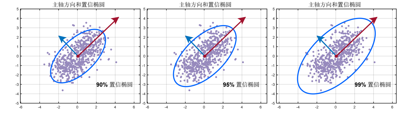
先来回顾一下按理说我本应该在平差课学习过,但我们那级莫名其妙没讲的概念——误差椭圆。我们都知道3σ原则,通俗地讲就是数的分布区间,在一维层面上也就是置信区间/置信水平;那么我们对点的定位,通常是二维或者三维的,也就是说我们不再能用一维的描述来表达我们点定位的水平了,置信椭圆就是二维层面上(有的时候更高维也可以叫置信椭圆,但像三维就应该是置信椭球了)描述一个点落在一个区间的概率。
代码里,是有一个简单的椭圆的结构体
struct Ellipse
{
  double long_radius;             // 椭圆的长轴
  double short_radius;            // 椭圆的短轴
  double yaw;                     // 椭圆的方向
  Eigen::Matrix2d P;              // 椭圆的协方差矩阵
  double size_lateral_direction;  // 椭圆的横向尺寸
};
node
这依旧是一个继承自rclcpp::Node的类,在构造函数中,有对里程计的订阅
  odom_sub_ = this->create_subscription<nav_msgs::msg::Odometry>(
    "input/odom", 1, std::bind(&LocalizationErrorMonitor::onOdom, this, std::placeholders::_1));
在onOdom函数里,就是对里程信息的处理,因为这里关注的是水平面的一个误差指标,所以只关注xy的协方差
  const auto cov = input_msg->pose.covariance;
  xy_covariance(0, 0) = cov[0 * 6 + 0];
  xy_covariance(0, 1) = cov[0 * 6 + 1];
  xy_covariance(1, 0) = cov[1 * 6 + 0];
  xy_covariance(1, 1) = cov[1 * 6 + 1];
然后对矩阵进行特征分解,特征值对应的就是长短轴的大小了,这里又乘了一个scale_,我觉得这里可能就是置信区间的意思吧,比如默认是3就对应着99.7%的区间?不是百分百确定
  Eigen::SelfAdjointEigenSolver<Eigen::Matrix2d> eigensolver(xy_covariance);

  // eigen values and vectors are sorted in ascending order
  ellipse_.long_radius = scale_ * std::sqrt(eigensolver.eigenvalues()(1));
  ellipse_.short_radius = scale_ * std::sqrt(eigensolver.eigenvalues()(0));
之后的yaw,也就是椭圆对应的方向,就是长轴对应的方向了,这个只需要找到对应的特征向量就可以
  const Eigen::Vector2d pc_vector = eigensolver.eigenvectors().col(1);
  ellipse_.yaw = std::atan2(pc_vector.y(), pc_vector.x());
至于水平方向的误差大小,是利用measureSizeEllipseAlongBodyFrame函数得到的,思路就是在横向上进行加权平均,这里的e对应的就是横向这个方向
double LocalizationErrorMonitor::measureSizeEllipseAlongBodyFrame(
  const Eigen::Matrix2d & Pinv, const double theta)
{
  Eigen::MatrixXd e(2, 1);
  e(0, 0) = std::cos(theta);
  e(1, 0) = std::sin(theta);

  double d = std::sqrt((e.transpose() * Pinv * e)(0, 0) / Pinv.determinant());
  return d;
}
当然,在onOdom里也生成了对应的可视化标志并进行了发布,这个就很简单了,没什么好说的。
除了根据运动信息得到椭圆,类中的updater_是用来实时监测误差水平的,分别调用了checkLocalizationAccuracy,是用来判断误差大小是否超过设置的;然后checkLocalizationAccuracyLateralDirection是用来判断方向是否超过限制的
  updater_.setHardwareID("localization_error_monitor");
  updater_.add("localization_accuracy", this, &LocalizationErrorMonitor::checkLocalizationAccuracy);
  updater_.add(
    "localization_accuracy_lateral_direction", this,
    &LocalizationErrorMonitor::checkLocalizationAccuracyLateralDirection);
这里用到的是ROS2中的diagnostic_updater::Updater,这个和ROS1中的diagnostics应该是一致的吧,之前看一个相机驱动的时候有看到过。这里主要就是通过add来添加诊断,然后会通过定时onTimer来定时更新状态信息


 被折叠的 条评论
为什么被折叠?
被折叠的 条评论
为什么被折叠?
 到【灌水乐园】发言


