


线激光到相机的光平面方程的标定
最近因业务需求,需要使用单线激光作为辅助传感器,在相机中获取激光线对应的深度信息进而获取到点云信息,为后续的任务服务,先列个提纲,后续慢慢补充。本项目代码当前使用python开发,主要使用到的库 opencv、numpy、pcl、open3d等
1.基本原理
1.1 光平面方程获取深度信息原理
通过相机的内参可以将图像坐标系上的点转换到相机坐标系,但是这得到的只能求得x,y,对于深度信息由于内参的标定过程涉及到深度方向上的归一化,因此无法获取深度信息,需要添加额外的约束条件,通过相机的光心高度是一种方法,另外一种方法就是使用激光的光平面方程,在得到相机坐标系下的光平面方程之后:
   cv::Point3f pixelToCamera(float px, float py, float fx, float fy, float cx, float cy)
{ return cv::Point3f((px - cx) / fx, (py - cy) / fy, 1.0); }
	增加约束条件:ax + by + cz +d = 0;即可求出z即目标点距离相机原点的深度信息
1.2 标定基本原理
由于光平面方程实际上就是在相机坐标系下建立的三元方程,因此,我们只需要在激光线中心点集合上获取在相机坐标系下至少三个不同线的点的坐标即可拟合出光平面方程,至于怎么得到在相机坐标系下的点,答案是外参,因此,在标定点的过程总我们必须将激光线照射在标定板上才能进行我们的标定工作。
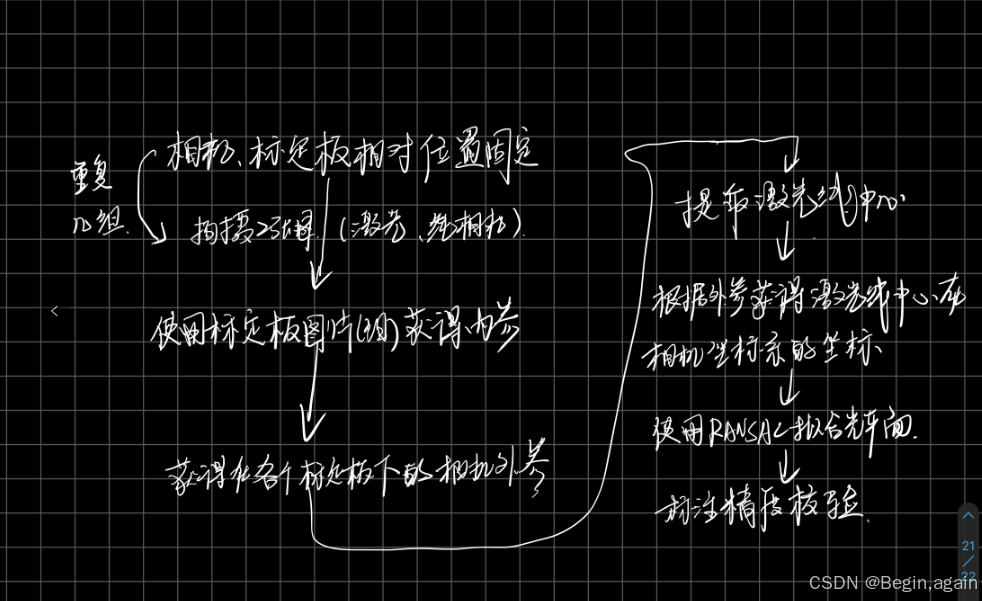
2.标定流程
- 拍摄多张标定板图片用于标定相机的内参
- 对于固定位置的标定板,拍摄两张图:激光、纯标定板
- 根据2拍摄到的图片获得相机的外参
- 对激光提点,提取到的激光点的世界坐标通过像素坐标的相对位置计算得到,再使用对应的外参将激光点的世界坐标转换到相机坐标系中
- 重复4得到在相机坐标中的一堆点(x,y,z),通过最小二乘法拟合激光平面方程
- 标定完成
- 验证
3.相关代码
本部分代码基本上包括了标定流程中中涉及到的所有代码,其中在获得激光线中心的时候主要用到灰度重心法,在将像素坐标转换到相机坐标主要用到了两种方法:交叉比不变性、比例法等。
3.1 内参标定代码
def get_inner_ir(self):
        self.image_path_list = glob("./{}/*.jpg".format(self.image_dir_path))
        for img_path in self.image_path_list:
            image = cv.imread(img_path)
            gray = cv.cvtColor(image, cv.COLOR_BGR2GRAY)
            ret, corners = cv.findChessboardCorners(gray, self.cheeseboard_size, None)
            if ret:
                criteria = (cv.TERM_CRITERIA_EPS + cv.TERM_CRITERIA_MAX_ITER, 30, 0.001)
                gray = cv.cvtColor(image, cv.COLOR_BGR2GRAY)
                corners_refined = cv.cornerSubPix(gray, corners, (11, 11), (-1, -1), criteria)
                self.world_points.append(self.add_world_points())
                self.image_points.append(corners_refined)
                if self.show_process:
                    image = cv.drawChessboardCorners(image, self.cheeseboard_size, corners_refined, ret)
                    cv.namedWindow("inner_ir", cv.WINDOW_NORMAL)
                    cv.imshow("inner_ir", image)
                    cv.waitKey(100)
                    cv.destroyAllWindows()
3.2 外参标定代码
 def get_outer_ir(self, img_dir_path):
        self.image_path_list = glob(f"{img_dir_path}/*.jpg")
        world_points = []
        image_points = []
        image_list = []
        for img_path in self.image_path_list:
            image = cv.imread(img_path)
            gray = cv.cvtColor(image, cv.COLOR_BGR2GRAY)
            ret, corners = cv.findChessboardCorners(gray, self.cheeseboard_size, None)
            if ret:
                # 提取亚像素
                image_name = img_path.split("/")[-1].split(".")[0]
                lidar_index = img_path.split("/")[-3]
                image_list.append(f"{lidar_index}-{image_name}")
                criteria = (cv.TERM_CRITERIA_EPS + cv.TERM_CRITERIA_MAX_ITER, 30, 0.001)
                gray = cv.cvtColor(image, cv.COLOR_BGR2GRAY)
                corners_refined = cv.cornerSubPix(gray, corners, (11, 11), (-1, -1), criteria)
                world_points.append(self.add_world_points())
                image_points.append(corners_refined)
                # ret, rvec, tvec = cv.solvePnP(self.add_world_points(), corners_refined, self.mtx, self.dist)
                # print(rvec, tvec)
        ret, tmp1, tmp2, self.rvecs, self.tvecs = cv.calibrateCamera(world_points, \
                                        image_points, gray.shape[::-1], self.mtx, self.dist)
3.3 激光线提取代码
def extract_lidar_line(self, imgpath, vertify=False):
        self.lidar_image_points.clear()
        lidar_img = cv.imread(imgpath)
        lidar_img = self.undistort_img(lidar_img)
        correct_image = lidar_img.copy()
        correct_image = cv.cvtColor(correct_image, cv.COLOR_RGB2GRAY)
        image_show = cv.cvtColor(correct_image.copy(), cv.COLOR_GRAY2RGB)
        img_gauss = cv.GaussianBlur(correct_image.copy(), (0, 0), 1.1)
        max_col_scalar = np.amax(img_gauss, axis=0)
        for i in range(img_gauss.shape[1]):
            threshold = max(max_col_scalar[i] - 20, 200)
            img_gauss[:, i] = np.where(img_gauss[:, i] < threshold, 0, img_gauss[:, i])
        if self.show_process:
            cv.namedWindow("img_gauss",0 )
            cv.imshow("img_gauss", img_gauss)
            cv.waitKey(0)
        img_after_remove_small_region = self.remove_small_region(img_gauss)

        # 找连通域轮廓
        contours, hierarchy = cv.findContours(img_after_remove_small_region, cv.RETR_EXTERNAL, cv.CHAIN_APPROX_NONE)

        # 获得的矩形区(左上角的点+宽高)
        bounding_rect = [cv.boundingRect(cnt) for cnt in contours]
        for i, contour in enumerate(contours):
            cv.drawContours(img_after_remove_small_region, contour, i, 0, cv.FILLED)
            self.gray_center(img_after_remove_small_region, bounding_rect[i], 50)
        self.lidar_image_points.sort(key=lambda point: (point[0], point[1]))

         cv.circle(image_show, (round(self.calibpoint_img_topleft[0]), round(self.calibpoint_img_topleft[1])), 1, (0, 255, 0), -1)
         cv.circle(image_show, (round(self.calibpoint_img_bottomright[0]), round(self.calibpoint_img_bottomright[1])), 1, (0, 255, 0), -1)
         line = cv.fitLine(np.array(self.lidar_image_points), cv.DIST_L2, 0, 1e-2, 1e-2)
         vx, vy, x0, y0 = line[0], line[1], line[2], line[3]
         pt1 = (int(x0 - vx * 1000), int(y0 - vy * 1000))
         pt2 = (int(x0 + vx * 1000), int(y0 + vy * 1000))
         color = (0, 255, 0)  # 使用绿色绘制
         cv.line(image_show, pt1, pt2, color, 2)

        if self.show_process:
            cv.namedWindow("lidar_img", cv.WINDOW_NORMAL)
            cv.imshow("lidar_img", image_show)
            cv.waitKey(0)
        cv.destroyAllWindows()
        return vx, vy, x0, y0
    def gray_center(self, input_image, bounding_rect, threshold):
        P = []
        x_min = min(self.calibpoint_img_topleft[0], self.calibpoint_img_bottomright[0])
        x_max = max(self.calibpoint_img_topleft[0], self.calibpoint_img_bottomright[0])
        y_min = min(self.calibpoint_img_topleft[1], self.calibpoint_img_bottomright[1])
        y_max = max(self.calibpoint_img_topleft[1], self.calibpoint_img_bottomright[1])
        x, y, w, h = bounding_rect
        for i in range(y, y + h):
            sum_val = 0
            center_y = 0
            for j in range(x, x + w):
                s = input_image[i, j]
                if s:
                    sum_val += s
                    center_y += j * s
            if sum_val:
                center_y /= sum_val
                if input_image[i, int(center_y),] > 0:
                    P.append((center_y, i))
        if len(P) >= 3:
            for i in range(1, len(P) - 1):
                P[i] = (P[i][0], (P[i-1][1] + P[i][1] + P[i+1][1]) / 3)
        if P:
            avg_scalar = int(np.mean([input_image[int(round(y)), int(round(x))] for x, y in P]))

            if avg_scalar < threshold:
                P.clear()
        for x, y in P:
            if 0 <= x < input_image.shape[1] and 0 <= y < input_image.shape[0]:
                if input_image[int(round(y)), int(round(x))] > threshold:
                    if x_min<=round(x)<=x_max and y_min<=round(y)<=y_max:
                        self.lidar_image_points.append((x, y))
    def remove_small_region(self,input_image):
        output_image = input_image.copy()
        contours, hierarchy = cv.findContours(input_image, cv.RETR_EXTERNAL, cv.CHAIN_APPROX_NONE)
        for i, contour in enumerate(contours):
            if abs(cv.contourArea(contour)) < self.min_lidararea:
                cv.drawContours(output_image, contours, i, 0, cv.FILLED)
3.4 激光线图像坐标转换到相机坐标代码
3.4.1使用交叉比不变性获得激光线相机坐标
def get_lidar_world_points(self, vx, vy, x0, y0):
        self.lidar_world_points.clear()
        for index,linapara in enumerate(self.lineparas):
            a_img = linapara["caliblinepoint"][0][0][0]
            b_img = linapara["caliblinepoint"][-1][0][0]
            c_img = linapara["caliblinepoint"][1][0][0]
            print(f"a_img:{a_img}, b_img:{b_img}, c_img:{c_img}")
            a_w = 0
            b_w = 9 * (self.cheeseboard_size[0] - 1)
            c_w = 9 * 1
            print(f"a_w: {a_w}, b_w: {b_w}, c_w: {c_w}")
            kandpoint = linapara["kandpoint"]
            intersectionpoint = find_intersection(kandpoint[0][0], kandpoint[1][0], kandpoint[2][0], \
                                                   kandpoint[3][0],vx[0], vy[0], x0[0], y0[0])
            print(f"intersectionpoint:{intersectionpoint}")
            CR_img = ((intersectionpoint[0] - c_img) * (b_img - a_img)) / ((intersectionpoint[0] - a_img) * (b_img - c_img))
            print(f"cr_img:{CR_img}")

            # 交叉比不变性,解世界坐标中的交点位置 intersection_w
            # 修改后的公式根据 a, c, 交点, b 的顺序
            intersection_w = (b_w * c_w) / (b_w + CR_img * (c_w - b_w))
            print("inter:", intersection_w)
            lidar_world_point_x = intersection_w
            lidar_world_point_y = self.cell_size *index
            # 默认坐标系下,z轴朝前

            self.lidar_world_points.append((lidar_world_point_x, lidar_world_point_y, 1))
        print(f"self.lidar_world_points:{self.lidar_world_points}")

    def get_lidar_camera_points(self):
        R, _ = cv.Rodrigues(self.rvecs)
        for lidar_world_point in self.lidar_world_points:
            point_cam = R @ lidar_world_point + self.tvecs
            self.lidar_camera_points.append(point_cam)
3.4.2 根据比例法获得激光线相机坐标
#根据提取到的激光线的中心坐标,利用内、外参得到条纹中心的在相机坐标系下的坐标
def pixelToPoint(pixel, intrinsic, rvec, tvec):
        rmat, _ = cv.Rodrigues(rvec)
        # print(f"pixel:{pixel}")
        point2d = np.array([[pixel[0]], [pixel[1]], [1.0]])

        rmat_inv = np.linalg.inv(rmat)
        intrinsic_inv = np.linalg.inv(intrinsic)

        M1 = rmat_inv @ intrinsic_inv @ point2d
        M2 = rmat_inv @ tvec
        # print(f"M1:{M1}, M2:{M2}")
        s = -M2[2] / M1[2, 0]

        point3d = s * intrinsic_inv @ point2d

        return (-point3d[0, 0], -point3d[1, 0], -point3d[2, 0])
3.5 光平面方程拟合代码
 def fitcameraplane(self, use_ransac = False):
        if use_ransac:
             # 创建点云对象
            cloud = pcl.PointCloud(self.lidar_camera_points)
            seg = cloud.make_segmenter()
            seg.set_model_type(pcl.SACMODEL_PLANE)
            seg.set_method_type(pcl.SAC_RANSAC)
            seg.set_distance_threshold(0.1)
            inliers, coefficients = seg.segment()
            extracted_cloud = cloud.extract(inliers, negative=False)

            o3d_ori_cloud = o3d.geometry.PointCloud()
            o3d_ori_cloud.points = o3d.utility.Vector3dVector(self.lidar_camera_points)

            o3d_extract_cloud = o3d.geometry.PointCloud()
            o3d_extract_cloud.points = o3d.utility.Vector3dVector(extracted_cloud)

            # 创建平面
            plane_cloud = create_plane_mesh(coefficients, size=100, resolution=20)

            # 创建坐标轴
            axis_pcd = o3d.geometry.TriangleMesh.create_coordinate_frame(size=50, origin=[0, 0, 0])

            # 可视化点云和坐标轴
            o3d.visualization.draw_geometries([o3d_extract_cloud, axis_pcd, plane_cloud])
            # o3d.visualization.draw_geometries([o3d_extract_cloud, axis_pcd])
            # print(f"ori_shape:{np.array(self.lidar_camera_points).shape}, extract_shape:{np.array(extracted_cloud).shape}")
            self.planeparams = [-coefficients[0]/coefficients[3], -coefficients[1]/coefficients[3],-coefficients[2]/coefficients[3]]
            self.planeparams_noinit = coefficients
            print(f"光平面方程:{self.planeparams_noinit}")
        else:
            A, B, C, D = 0, 0, 0, 0
            meanX = meanY = meanZ = 0
            meanXX = meanYY = meanZZ = 0
            meanXY = meanXZ = meanYZ = 0
            for pt in self.lidar_camera_points:
                meanX += pt[0]
                meanY += pt[1]
                meanZ += pt[2]

                meanXX += pt[0] * pt[0]
                meanYY += pt[1] * pt[1]
                meanZZ += pt[2] * pt[2]

                meanXY += pt[0] * pt[1]
                meanXZ += pt[0] * pt[2]
                meanYZ += pt[1] * pt[2]

            n = len(self.lidar_camera_points)
            meanX /= n
            meanY /= n
            meanZ /= n
            meanXX /= n
            meanYY /= n
            meanZZ /= n
            meanXY /= n
            meanXZ /= n
            meanYZ /= n
            m = np.array([[meanXX - meanX * meanX, meanXY - meanX * meanY, meanXZ - meanX * meanZ],
                        [meanXY - meanX * meanY, meanYY - meanY * meanY, meanYZ - meanY * meanZ],
                        [meanXZ - meanX * meanZ, meanYZ - meanY * meanZ, meanZZ - meanZ * meanZ]])
            eigenvalues, eigenvectors = cv.eigen(m)[1:3]
            eigenvalues = np.abs(eigenvalues.flatten())
            min_index = np.argmin(eigenvalues)
            A, B, C = eigenvectors[min_index]
            D = -(A * meanX + B * meanY + C * meanZ)
            if C < 0:
                A *= -1.0
                B *= -1.0
                C *= -1.0
                D *= -1.0
            self.planeparams = [-A / D, -B / D, -C / D]
3.6 标定结果可视化代码
def evaluate_calib_error(self, vertify_calibpath, vertify_lidarpath):
        self.calibpoint_img_topleft = [0, 0]
        self.calibpoint_img_bottomright = [1000, 1000]
        cam_cross_points = []
        plane_a, plane_b, plane_c = self.planeparams
        fx, cx, fy, cy = self.mtx[0][0], self.mtx[0][2], self.mtx[1][1], self.mtx[1][2]
        # print(f"fx:{fx},fy:{fy}")
        self.extract_lidar_line(vertify_lidarpath, vertify=True)
        for image_point in self.lidar_image_points:
            img_cross_x = image_point[0]
            img_cross_y = image_point[1]
            cam_cross_x_ = (img_cross_x - cx) / fx
            cam_cross_y_ = (img_cross_y - cy) / fy
            cam_cross_z = 1/(plane_a*cam_cross_x_ + plane_b*cam_cross_y_ + plane_c)
            cam_cross_x = cam_cross_z * cam_cross_x_
            cam_cross_y = cam_cross_z * cam_cross_y_
            cam_cross_points.append([cam_cross_x, cam_cross_y, cam_cross_z])
        thetaPitch = np.deg2rad(-6.7)  # 将角度转换为弧度
        thetaRoll = np.deg2rad(-3.7)
        R_x = np.array([[1, 0, 0],
                        [0, np.cos(thetaPitch), -np.sin(thetaPitch)],
                        [0, np.sin(thetaPitch), np.cos(thetaPitch)]])
        R_z = np.array([[np.cos(thetaRoll), -np.sin(thetaRoll), 0],
                [np.sin(thetaRoll), np.cos(thetaRoll), 0],
                [0, 0, 1]])
        print(R_x)
        point_cloud_data = np.array(cam_cross_points)
        point_cloud_data = point_cloud_data
        # print(f"point_cloud_data:{point_cloud_data}")
        x = point_cloud_data[:, 0]
        y = point_cloud_data[:, 1]
        z = point_cloud_data[:, 2]

        slope_x, intercept = np.polyfit(z, y, 1)
        slope_z, intercept = np.polyfit(x, y, 1)
        slope_y, intercept = np.polyfit(z, x, 1)
        print(f"偏转角度: {math.atan(slope_x)/math.pi*180} {math.atan(slope_y)/math.pi*180} {math.atan(slope_z)/math.pi*180}")
        print(f"point_cloud_data:{point_cloud_data}")
        o3d_ori_cloud = o3d.geometry.PointCloud()
        o3d_ori_cloud.points = o3d.utility.Vector3dVector(point_cloud_data)
        plane_cloud = create_plane_mesh(self.planeparams_noinit, size=100, resolution=20)

        # # 创建坐标轴
        axis_pcd = o3d.geometry.TriangleMesh.create_coordinate_frame(size=50, origin=[0, 0, 0])

        # # 可视化点云和坐标轴
        o3d.visualization.draw_geometries([o3d_ori_cloud, axis_pcd, plane_cloud])


 5531
5531

 被折叠的 条评论
为什么被折叠?
被折叠的 条评论
为什么被折叠?
 到【灌水乐园】发言


