


1. Arbotix
1.1 添加配置文件
# 该文件是控制器配置,一个机器人模型可能有多个控制器,比如: 底盘、机械臂、夹持器(机械手)....
# 因此,根 name 是 controller
controllers: {
   # 单控制器设置
   base_controller: {
          #类型: 差速控制器
       type: diff_controller,
       #参考坐标
       base_frame_id: base_footprint,
       #两个轮子之间的间距
       base_width: 0.2,
       #控制频率
       ticks_meter: 2000,
       #PID控制参数,使机器人车轮快速达到预期速度
       Kp: 12,
       Kd: 12,
       Ki: 0,
       Ko: 50,
       #加速限制
       accel_limit: 1.0
    }
}
放在config里,建一个yaml文件

差速控制器:通过两个轮子速度差实现各种动作
参考坐标系:一般是根坐标系
1.2 launch文件编写
在以往基础上增加这些
    <node pkg="arbotix_python" type="arbotix_driver" name="driver" output="screen">
        <rosparam command="load" file="$(find urdf1_rviz)/config/control.yaml"/>
        <param name="sim" value="true"/>
    </node>
WARRING:把bashrc文件的IP地址换成本地的
订阅运动话题
参考坐标系换成odom(初始位置)
2. gazebo
2.1 URDF集成gazebo
src下新建有文件夹urdf的目录,依赖:
urdf xacro gazebo_ros gazebo_ros_control gazebo_plugins

编码如下:
<robot name="car">
<link name="base_link">
<visual>
<geometry>
<box size="0.5 0.4 0.3"/>
</geometry>
<origin xyz="0.0 0.0 0.0" rpy="0.0 0.0 0.0" />
<material name="color">
<color rgba="0.5 0.5 0.4 0.5" />
</material>
</visual>
<collision>
<geometry>
<box size="0.5 0.4 0.3"/>
</geometry>
<origin xyz="0.0 0.0 0.0" rpy="0.0 0.0 0.0" />
</collision>
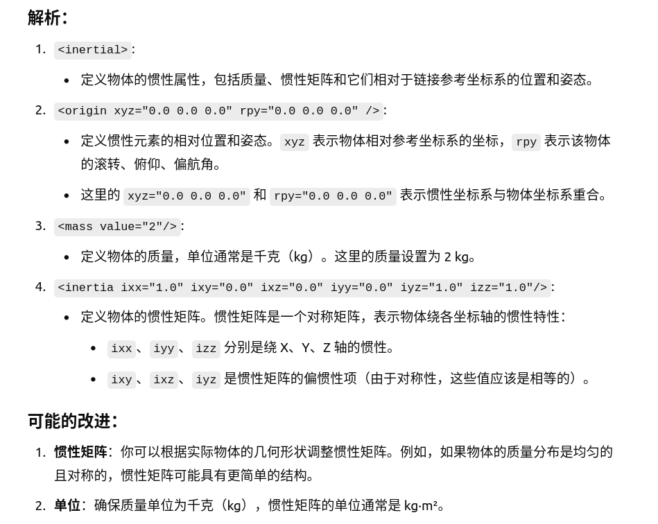
<inertial>
<origin xyz="0.0 0.0 0.0" rpy="0.0 0.0 0.0" />
<mass value="2"/>
<inertia ixx="1.0" ixy="0.0" ixz="0.0" iyy="0.0" iyz="1.0" izz="1.0"/>
</inertial>
</link>
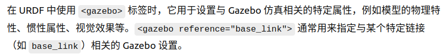
<gazebo reference="base_link">
<material>Gazebo/Blue</material>
</gazebo>
</robot>
代码详解
collision(设置碰撞模型)
collision里的是碰撞模型,一般情况下和Robot保持一致
inertial(惯性设置)
origin:质量坐标系
masss:质量 单位:kg
inertial:惯性矩阵 单位:kg·m²
一般要用到的惯性矩阵
球体:
<!-- Macro for inertia matrix -->
    <xacro:macro name="sphere_inertial_matrix" params="m r">
        <inertial>
            <mass value="${m}" />
            <inertia ixx="${2*m*r*r/5}" ixy="0" ixz="0"
                iyy="${2*m*r*r/5}" iyz="0"
                izz="${2*m*r*r/5}" />
        </inertial>
    </xacro:macro>
圆柱:
<xacro:macro name="cylinder_inertial_matrix" params="m r h">
        <inertial>
            <mass value="${m}" />
            <inertia ixx="${m*(3*r*r+h*h)/12}" ixy = "0" ixz = "0"
                iyy="${m*(3*r*r+h*h)/12}" iyz = "0"
                izz="${m*r*r/2}" />
        </inertial>
    </xacro:macro>
立方体:
 <xacro:macro name="Box_inertial_matrix" params="m l w h">
       <inertial>
               <mass value="${m}" />
               <inertia ixx="${m*(h*h + l*l)/12}" ixy = "0" ixz = "0"
                   iyy="${m*(w*w + l*l)/12}" iyz= "0"
                   izz="${m*(w*w + h*h)/12}" />
       </inertial>
   </xacro:macro>
gazebo
注意:仿真环境中没有透明度的说法,所以这里颜色必须重新设置(注意大小写)
2.2 launch文件编写
<launch>
    <param name="robot_description" textfile="$(find urdf_gazebo)/urdf/demo1.urdf" />
    <include file="$(find gazebo_ros)/launch/empty_world.launch"/> //启动gazebo
    <node pkg="gazebo_ros" type="spawn_model" name="spawn_model" args="-urdf -model car_demo -param robot_description" />//载入模型

</launch>
2.3 加载地图
新建worlds文件夹,将地图资源导入
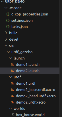
launch修改如下
<launch>
    <param name="robot_description" command="$(find xacro)/xacro $(find urdf_gazebo)/urdf/demo2.urdf.xacro" />
    <include file="$(find gazebo_ros)/launch/empty_world.launch">
        <arg name="world_name" value="$(find urdf_gazebo)/worlds/box_house.world" />
    </include>
    <node pkg="gazebo_ros" type="spawn_model" name="spawn_model" args="-urdf -model my_car -param robot_description" />
</launch>
3.roscontrol
3.1 运动控制
在urdf下新建gazebo文件夹,新建文件:
<robot name="my_car_move" xmlns:xacro="http://wiki.ros.org/xacro">

    <!-- 传动实现:用于连接控制器与关节 -->
    <xacro:macro name="joint_trans" params="joint_name">
        <!-- Transmission is important to link the joints and the controller -->
        <transmission name="${joint_name}_trans">
            <type>transmission_interface/SimpleTransmission</type>
            <joint name="${joint_name}">
                <hardwareInterface>hardware_interface/VelocityJointInterface</hardwareInterface>
            </joint>
            <actuator name="${joint_name}_motor">
                <hardwareInterface>hardware_interface/VelocityJointInterface</hardwareInterface>
                <mechanicalReduction>1</mechanicalReduction>
            </actuator>
        </transmission>
    </xacro:macro>

    <!-- 每一个驱动轮都需要配置传动装置 -->
    <xacro:joint_trans joint_name="left_wheel2base_link" />
    <xacro:joint_trans joint_name="right_wheel2base_link" />

    <!-- 控制器 -->
    <gazebo>
        <plugin name="differential_drive_controller" filename="libgazebo_ros_diff_drive.so">
            <rosDebugLevel>Debug</rosDebugLevel>
            <publishWheelTF>true</publishWheelTF>
            <robotNamespace>/</robotNamespace>
            <publishTf>1</publishTf>
            <publishWheelJointState>true</publishWheelJointState>
            <alwaysOn>true</alwaysOn>
            <updateRate>100.0</updateRate>
            <legacyMode>true</legacyMode>
            <leftJoint>left_wheel2base_link</leftJoint> <!-- 左轮 -->
            <rightJoint>right_wheel2base_link</rightJoint> <!-- 右轮 -->
            <wheelSeparation>${base_link_radius * 2}</wheelSeparation> <!-- 车轮间距 -->
            <wheelDiameter>${wheel_radius * 2}</wheelDiameter> <!-- 车轮直径 -->
            <broadcastTF>1</broadcastTF>
            <wheelTorque>30</wheelTorque>
            <wheelAcceleration>1.8</wheelAcceleration>
            <commandTopic>cmd_vel</commandTopic> <!-- 运动控制话题 -->
            <odometryFrame>odom</odometryFrame>
            <odometryTopic>odom</odometryTopic> <!-- 里程计话题 -->
            <robotBaseFrame>base_footprint</robotBaseFrame> <!-- 根坐标系 -->
        </plugin>
    </gazebo>

</robot>
结合标签将内容修改为正确的
将文件集成
<xacro:include filename="gazebo/move.xacro"/>
3.2 里程计使用
复用之前的rviz
<launch>
    <node name="rviz" pkg="rviz" type="rviz" args="-d $(find urdf1_rviz)/config/show_car.rviz"/>

    <node name="joint_state_publisher" pkg="joint_state_publisher" type="joint_state_publisher"/>
    <node name="robot_state_publisher" pkg="robot_state_publisher" type="robot_state_publisher"/>
</launch>
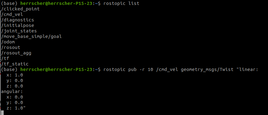
启动gazebo后启动rviz
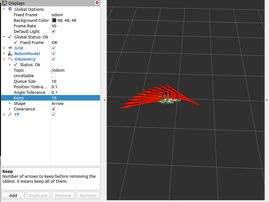
配置如下
启动键盘控制

里程计会显示小车的路径
3.3 雷达仿真
和运动控制差不多,先新建雷达的xacro,复制文件如下
<robot name="my_sensors" xmlns:xacro="http://wiki.ros.org/xacro">

  <!-- 雷达 -->
  <gazebo reference="laser">
    <sensor type="ray" name="rplidar">
      <pose>0 0 0 0 0 0</pose>
      <visualize>true</visualize>
      <update_rate>5.5</update_rate>
      <ray>
        <scan>
          <horizontal>
            <samples>360</samples>
            <resolution>1</resolution>
            <min_angle>-3</min_angle>
            <max_angle>3</max_angle>
          </horizontal>
        </scan>
        <range>
          <min>0.10</min>
          <max>30.0</max>
          <resolution>0.01</resolution>
        </range>
        <noise>
          <type>gaussian</type>
          <mean>0.0</mean>
          <stddev>0.01</stddev>
        </noise>
      </ray>
      <plugin name="gazebo_rplidar" filename="libgazebo_ros_laser.so">
        <topicName>/scan</topicName>
        <frameName>laser</frameName>
      </plugin>
    </sensor>
  </gazebo>

</robot>
启动后效果如图
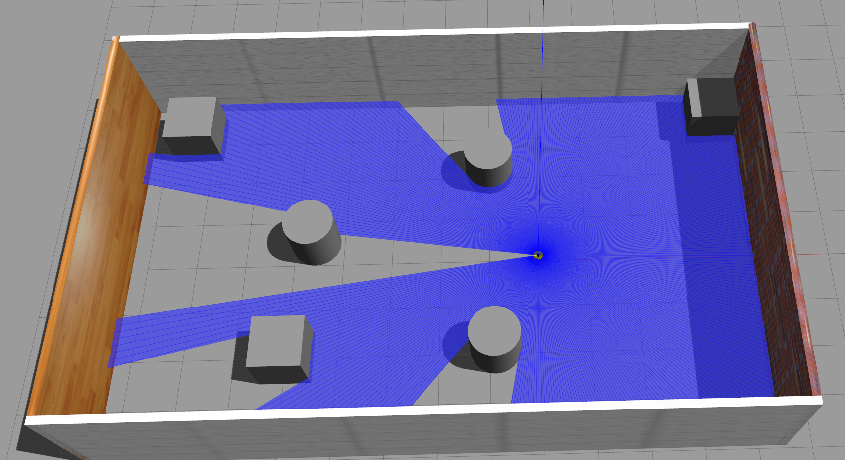
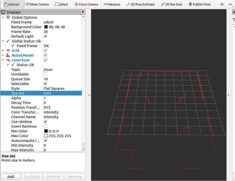
size可以改动标记的大小
参数解释
<gazebo reference="laser">
雷达关联的连杆
<frameName>laser</frameName>
雷达的坐标系,和连杆一样就行
<pose>0 0 0 0 0 0</pose>
xyz,rpy
<visualize>true</visualize>
雷达射线是否显示(gazebo里蓝色的)
<update_rate>5.5</update_rate>
雷达信息的更新频率(hz)
            <samples>360</samples>
            <resolution>1</resolution>
            <min_angle>-3</min_angle>
            <max_angle>3</max_angle>
分别是雷达发出射线的数量
每几个射线里有一个用于测距
扫描的左右弧度
          <min>0.10</min>
          <max>30.0</max>
          <resolution>0.01</resolution>
雷达的最小可见范围和最大可见范围
精度
          <type>gaussian</type>
          <mean>0.0</mean>
          <stddev>0.01</stddev>
高斯噪音
实际情况下雷达的测量并不总是准确的(可以参考高中物理的计算题),加入高斯噪音可以模拟这种误差
3.5 摄像头仿真
<robot name="my_sensors" xmlns:xacro="http://wiki.ros.org/xacro">
  <!-- 被引用的link -->
  <gazebo reference="camera">
    <!-- 类型设置为 camara -->
    <sensor type="camera" name="camera_node">
      <update_rate>30.0</update_rate> <!-- 更新频率 -->
      <!-- 摄像头基本信息设置 -->
      <camera name="head">
        <horizontal_fov>1.3962634</horizontal_fov>
        <image>
          <width>1280</width>
          <height>720</height>
          <format>R8G8B8</format>
        </image>
        <clip>
          <near>0.02</near>
          <far>300</far>
        </clip>
        <noise>
          <type>gaussian</type>
          <mean>0.0</mean>
          <stddev>0.007</stddev>
        </noise>
      </camera>
      <!-- 核心插件 -->
      <plugin name="gazebo_camera" filename="libgazebo_ros_camera.so">
        <alwaysOn>true</alwaysOn>
        <updateRate>0.0</updateRate>
        <cameraName>/camera</cameraName>
        <imageTopicName>image_raw</imageTopicName>
        <cameraInfoTopicName>camera_info</cameraInfoTopicName>
        <frameName>camera</frameName>
        <hackBaseline>0.07</hackBaseline>
        <distortionK1>0.0</distortionK1>
        <distortionK2>0.0</distortionK2>
        <distortionK3>0.0</distortionK3>
        <distortionT1>0.0</distortionT1>
        <distortionT2>0.0</distortionT2>
      </plugin>
    </sensor>
  </gazebo>
</robot>
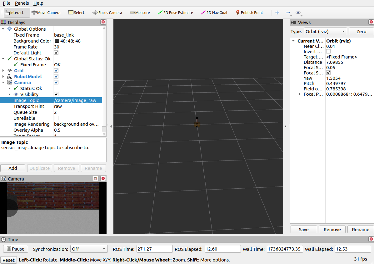
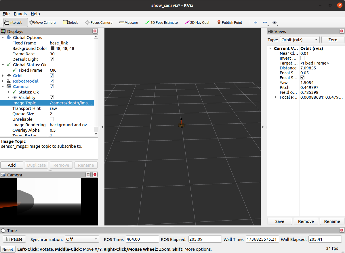
rviz设置如下,可以看到摄像头的视野
3.6深度相机
<robot name="my_sensors" xmlns:xacro="http://wiki.ros.org/xacro">
    <gazebo reference="kinect link名称">
      <sensor type="depth" name="camera">
        <always_on>true</always_on>
        <update_rate>20.0</update_rate>
        <camera>
          <horizontal_fov>${60.0*PI/180.0}</horizontal_fov>
          <image>
            <format>R8G8B8</format>
            <width>640</width>
            <height>480</height>
          </image>
          <clip>
            <near>0.05</near>
            <far>8.0</far>
          </clip>
        </camera>
        <plugin name="kinect_camera_controller" filename="libgazebo_ros_openni_kinect.so">
          <cameraName>camera</cameraName>
          <alwaysOn>true</alwaysOn>
          <updateRate>10</updateRate>
          <imageTopicName>rgb/image_raw</imageTopicName>
          <depthImageTopicName>depth/image_raw</depthImageTopicName>
          <pointCloudTopicName>depth/points</pointCloudTopicName>
          <cameraInfoTopicName>rgb/camera_info</cameraInfoTopicName>
          <depthImageCameraInfoTopicName>depth/camera_info</depthImageCameraInfoTopicName>
          <frameName>kinect link名称</frameName>
          <baseline>0.1</baseline>
          <distortion_k1>0.0</distortion_k1>
          <distortion_k2>0.0</distortion_k2>
          <distortion_k3>0.0</distortion_k3>
          <distortion_t1>0.0</distortion_t1>
          <distortion_t2>0.0</distortion_t2>
          <pointCloudCutoff>0.4</pointCloudCutoff>
        </plugin>
      </sensor>
    </gazebo>

</robot>
kinect和camera可以设置在同一连杆上
3.8 kinect点云
rviz中可以以点云的方式显示图形
但是启动点云时会发生这种情况(x轴和z轴都偏移了90度)
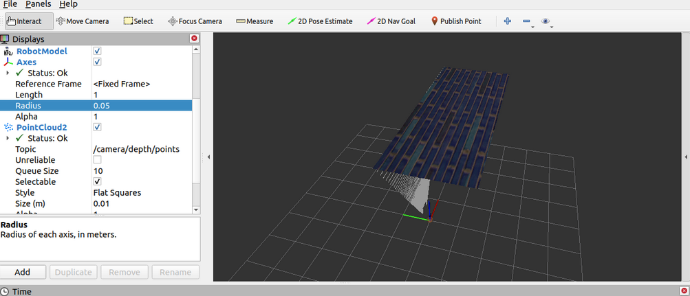 这是因为kinect中点云和图像数据分别使用了两套坐标系
可以将坐标系进行修改和转换
kinect:
<frameName>support_depth</frameName>
rviz.launch
<node pkg="tf2_ros" type="static_transform_publisher" name="static_transform_publisher" args="0 0 0 -1.57 0 -1.57 /support /support_depth" />


 1万+
1万+

 被折叠的 条评论
为什么被折叠?
被折叠的 条评论
为什么被折叠?
 到【灌水乐园】发言


