


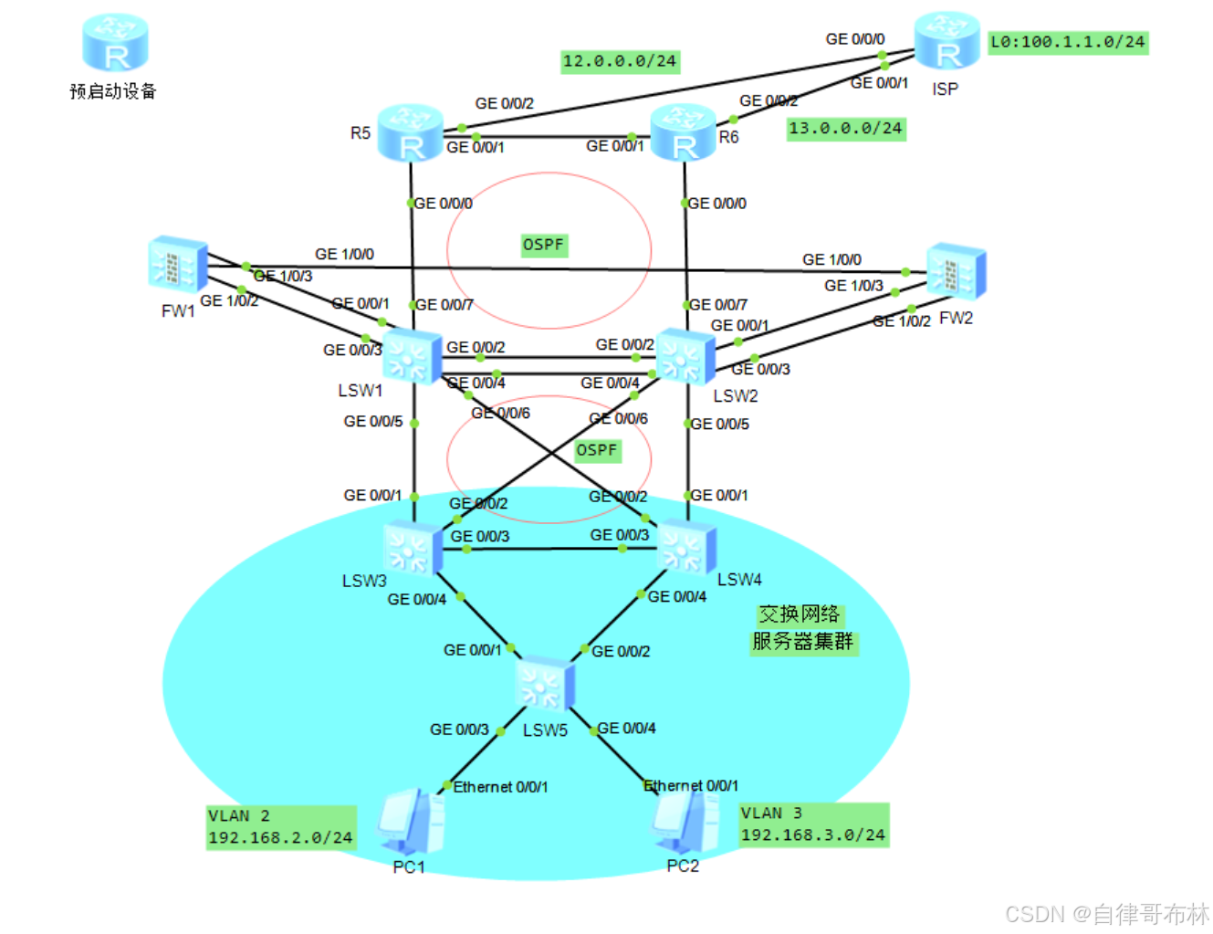
实验内容、需求及分析
需求:
1、SW3的流量
正常情况下:SW1_VRF-->FW1--->SW1_Public--->R5
故障情况下:SW2_VRF-->FW2--->SW2_Public--->R6
2、SW4的流量
正常情况下:SW2_VRF-->FW2--->SW2_Public--->R6
故障情况下:SW1_VRF-->FW1--->SW1_Public--->R5
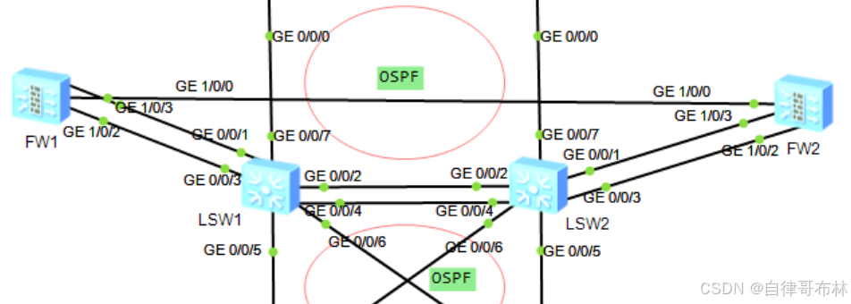
3、交换网络负载均衡旁挂优点:
1、在不影响网络物理拓扑的情况下,将防火墙加入到现有网络中
2、可以有选择性的将流量引导到防火墙进行安全检测旁挂的引导流量方式:1.静态路由;2.策略路由。
在实际组网环境中,来回流量都需要经过防火墙的安全检查。
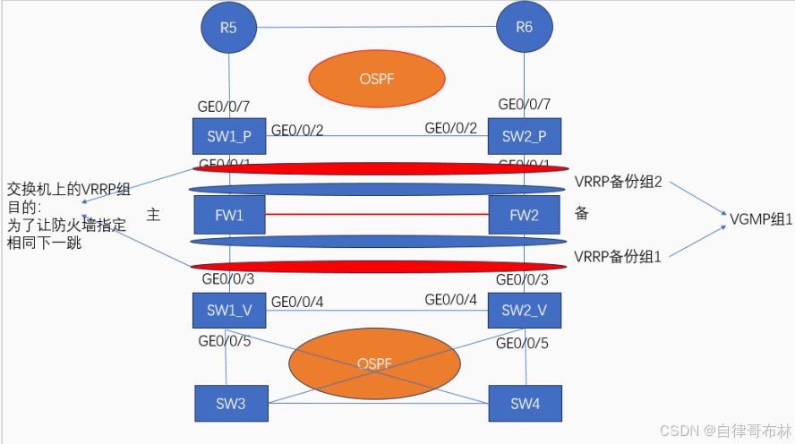
通过静态路由方式,将流经核心交换机的流量引导到防火墙,需要在核心交换机上配置静态路由---->下一跳为防火墙的地址
问题:一般核心交换机会和上下游设备共同运行OSPF协议,而OSPF协议优先级高于静态路由,导致前面配置的静态路由失效,及流量无法被引导到防火墙
在核心交换机上配置VPF功能---虚拟路由转发实例
将一台设备虚拟成多台交换机
将一台设备进行分割,变为多台设备,并且虚拟出来的设备与原本的设备是相互完全隔离,路由之间互不干扰,接口之间互不干扰。
为了实现流量的转发,需要在交换机的VRF和Public上配置静态路由,下一跳为VRRP备份组1和 VRRP备份组2的虚拟IP地址。因为流量是有去有回的,所以防火墙上也需要配置两条静态的回程路由, 下一跳分别是VRF和Public的VRRP组的虚拟IP地址。
配置
二层交换配置
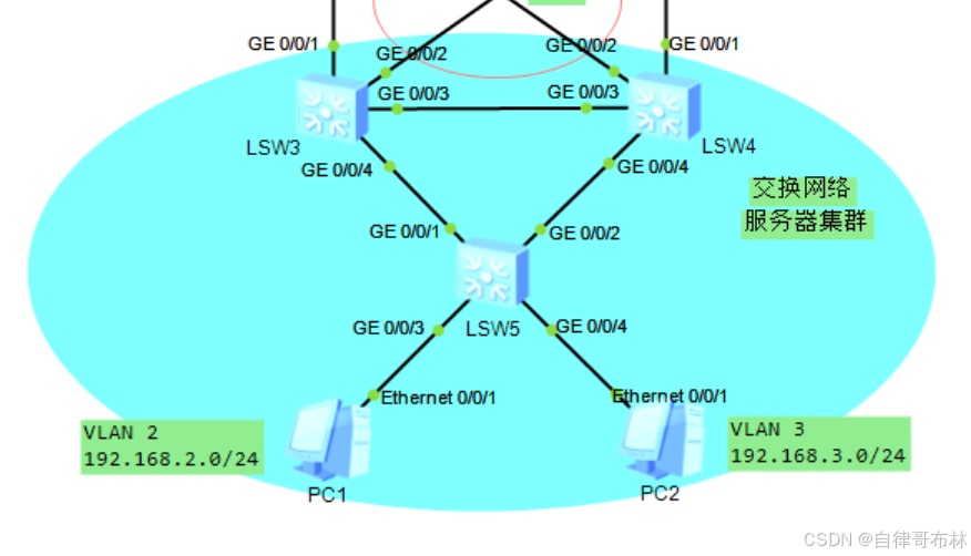
使用传统三层架构中MSTP+VRRP组网形式
VLAN 2--->SW3,SW4作为备份
VLAN 3--->SW4,SW3作为备份

MSTP设计--->SW3、4、5运行
实例1:VLAN 2
实例2:VLAN 3
SW3是实例1的主根,实例2的备份根;SW4是实例2的主根,实例1的备份根

IP地址规划:
SW3:
VLAN 2:192.168.2.1/24
VLAN 3:192.168.3.1/24
SW4:
VLAN 2:192.168.2.2/24
VLAN 3:192.168.3.2/24

虚拟IP:
VLAN 2:192.168.2.254/24
VLAN 3:192.168.3.254/24
SW3 配置
生成树配置
[SW3]stp enable
[SW3]stp mode mstp
[SW3]stp region-configuration
[SW3-mst-region]region-name aa
[SW3-mst-region]instance 1 vlan 2
[SW3-mst-region]instance 2 vlan 3
[SW3-mst-region]active region-configuration
[SW3]stp instance 1 root primary
[SW3]stp instance 2 root secondary
[SW3]stp instance 0 root primary
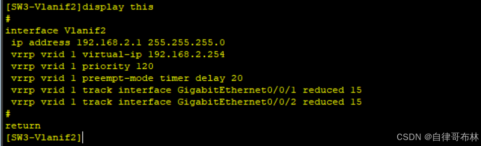
[SW3]interface Vlanif 2
[SW3-Vlanif2]ip address 192.168.2.1 24
[SW3-Vlanif2]vrrp vrid 1 virtual-ip 192.168.2.254
[SW3-Vlanif2]vrrp vrid 1 priority 120(比默认值100大即可)
[SW3-Vlanif2]vrrp vrid 1 preempt-mode timer delay 20 抢占延时
[SW3-Vlanif2]vrrp vrid 1 track interface GigabitEthernet 0/0/1 reduced 15
[SW3-Vlanif2]vrrp vrid 1 track interface GigabitEthernet 0/0/2 reduced 15
[SW3]interface Vlanif 3
[SW3-Vlanif3]ip address 192.168.3.1 24
[SW3-Vlanif3]vrrp vrid 1 virtual-ip 192.168.3.254
SW4配置
[SW4]stp enable
[SW4]stp mode mstp
[SW4]stp region-configuration
[SW4-mst-region]region-name aa
[SW4-mst-region]instance 1 vlan 2
[SW4-mst-region]instance 2 vlan 3
[SW4-mst-region]active region-configuration
[SW4]stp instance 1 root secondary
[SW4]stp instance 2 root primary
[SW4]stp instance 0 root secondary


[SW4]interface Vlanif 2
[SW4-Vlanif2]ip address 192.168.2.2 24
[SW4-Vlanif2]vrrp vrid 1 virtual-ip 192.168.2.254
SW4]interface Vlanif 3
[SW4-Vlanif3]ip address  192.168.3.2 24
[SW4-Vlanif3]vrrp vrid 1 virtual-ip 192.168.3.254
[SW4-Vlanif3]vrrp vrid 1 preempt-mode  timer delay  20
[SW4-Vlanif3]vrrp vrid 1 track interface GigabitEthernet 0/0/1 reduced 15
[SW4-Vlanif3]vrrp vrid 1 track interface GigabitEthernet 0/0/2 reduced 15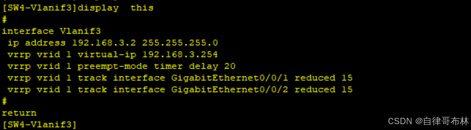
SW5配置
[SW5]stp enable
[SW5]stp mode mstp
[SW5]stp region-configuration
[SW5-mst-region]region-name aa
[SW5-mst-region]instance 1 vlan  2
[SW5-mst-region]instance 2 vlan  3
[SW5-mst-region]active  region-configuration
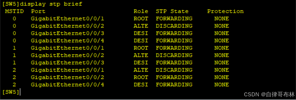
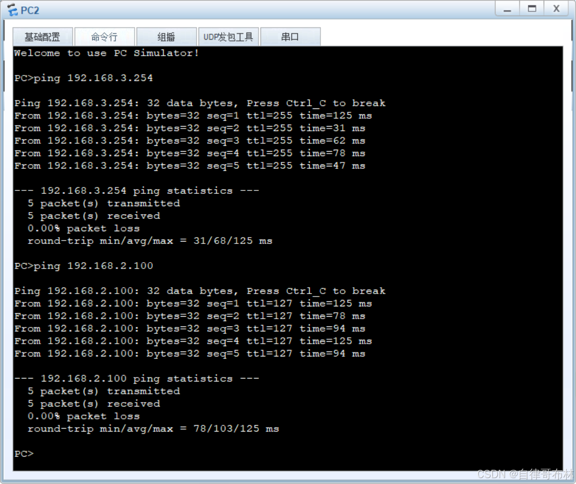
Ping网关和PC1成功,二层交换配置完成
汇聚到核心层路由配置
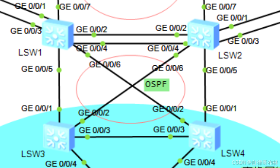
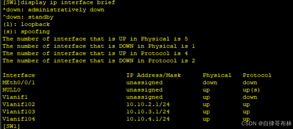
SW1-SW2:VLAN 102---10.10.2.0/24
SW1-SW3:VLAN 103---10.10.3.0/24
SW1-SW4:VLAN 104---10.10.4.0/24
SW2-SW3:VLAN 203---10.20.3.0/24
SW2-SW4:VLAN 204---10.20.4.0/24

因为SW1和SW2需要被分割为两台设备,分别与上下行设备连接,故需要先创建VRF空间,其中
GE0/0/3-GE0/0/6属于该空间接口。

VRF空间配置信息:
名称:VRF
RD:100:1
RT:100:1

[sw1]ip vpn-instance VRF ---创建VRF空间
[sw1-vpn-instance-VRF]route-distinguisher 100:1 --设定RD值
[sw1-vpn-instance-VRF-af-ipv4]vpn-target 100:1 both ---设定RT值
[sw1-Vlanif102]ip binding vpn-instance VRF ----将接口划入到VRF这个交换机中,在接口进行
配置之前执行
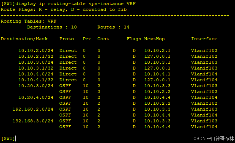
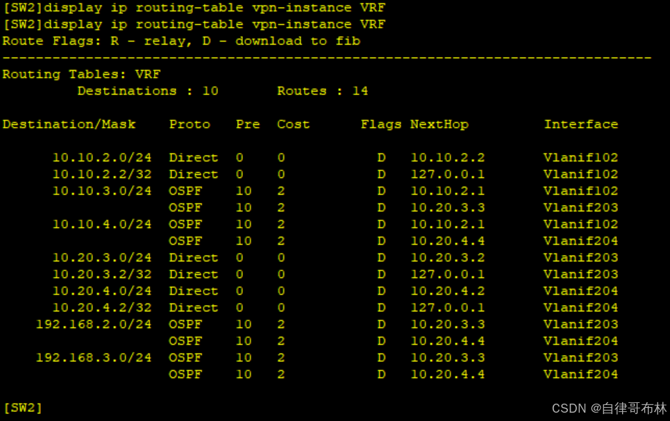
因为VPN实例和物理设备,之间的完全相互独立的,所以,路由表、MAC地址表等各类信息也是独 立的互不干扰的,所以,在进行配置时,需要携带vpn-instance参数,设备才会知晓使用哪个设备的表单。
SW3配置
[SW3]interface Vlanif 103
[SW3-Vlanif103]ip address 10.10.3.3 24
[SW3]interface Vlanif 203
[SW3-Vlanif203]ip address 10.20.3.3 24
[SW3]ospf 1 router-id 3.3.3.3
[SW3-ospf-1]area 0
[SW3-ospf-1-area-0.0.0.0]network 10.20.3.3 0.0.0.0
[SW3-ospf-1-area-0.0.0.0]network 10.10.3.3 0.0.0.0
[SW3-ospf-1-area-0.0.0.0]network 192.168.2.1 0.0.0.0
[SW3-ospf-1-area-0.0.0.0]network 192.168.3.1 0.0.0.0

配置静默接口
[SW3-ospf-1]silent-interface Vlanif 2
[SW3-ospf-1]silent-interface Vlanif 3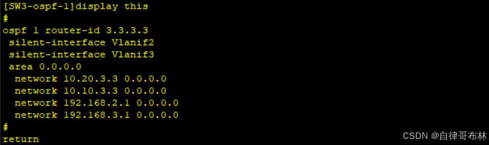
SW4配置
[SW4]interface Vlanif 104
[SW4-Vlanif104]ip address 10.10.4.4 24
[SW4]interface Vlanif 204
[SW4-Vlanif204]ip address 10.20.4.4 24
[SW4]ospf 1 router-id 4.4.4.4
[SW4-ospf-1-area-0.0.0.0]network 10.10.4.4 0.0.0.0
[SW4-ospf-1-area-0.0.0.0]network 10.20.4.4 0.0.0.0
[SW4-ospf-1-area-0.0.0.0]network 192.168.2.2 0.0.0.0
[SW4-ospf-1-area-0.0.0.0]network 192.168.3.2 0.0.0.0

配置静默接口
[SW4-ospf-1]silent-interface Vlanif 2
[SW4-ospf-1]silent-interface Vlanif 3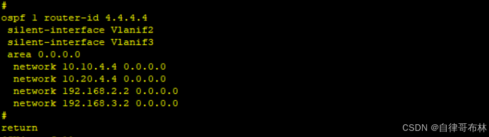
SW1配置
[sw1]ip vpn-instance VRF ---创建VRF空间
[sw1-vpn-instance-VRF]route-distinguisher 100:1 --设定RD值
[sw1-vpn-instance-VRF-af-ipv4]vpn-target 100:1 both ---设定RT值


[SW1]interface Vlanif 102
[SW1-Vlanif102]ip address 10.10.2.1 24

[SW1-Vlanif102]ip binding vpn-instance VRF
[SW1-Vlanif102]ip address 10.10.2.1 24
[SW1-Vlanif103]ip binding vpn-instance VRF
[SW1-Vlanif103]ip address 10.10.3.1 24
[SW1-Vlanif104]ip binding vpn-instance VRF
[SW1-Vlanif103]ip address 10.10.4.1 24
SW2配置
[sw2]ip vpn-instance VRF ---创建VRF空间
[sw2-vpn-instance-VRF]route-distinguisher 100:1 --设定RD值
[sw2-vpn-instance-VRF-af-ipv4]vpn-target 100:1 both ---设定RT值


[SW2-Vlanif102]ip binding vpn-instance VRF
[SW2-Vlanif102]ip address 10.10.2.2 24
[SW2-Vlanif203]ip binding vpn-instance VRF
[SW2-Vlanif203]ip address 10.20.3.2 24
[SW2-Vlanif204]ip binding vpn-instance VRF
[SW2-Vlanif204]ip address 10.20.4.2 24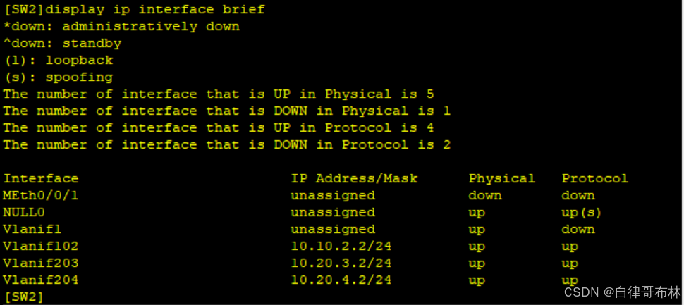
[SW3]int  v 203
[SW3-Vlanif203]ospf cost 5
[SW3-ospf-1]area 0
[SW3-ospf-1-area-0.0.0.0]undo network 192.168.2.1 0.0.0.0
[SW3-ospf-1-area-0.0.0.0]undo network 192.168.3.1 0.0.0.0

1、抓流量
[sw3]ip ip-prefix aa permit 192.168.3.0 24
[sw3]ip ip-prefix bb permit 192.168.2.0 24
2、做策略
[sw3]route-policy aa permit node 10
[sw3-route-policy]if-match ip-prefix aa
[sw3-route-policy]apply cost 5
[sw3]route-policy aa permit node 20
[sw3-route-policy]if-match ip-prefix bb
3、调用
[sw3-ospf-1]import-route direct route-policy aa


[SW4]int v 104
[SW4-Vlanif104]ospf cost 5
[SW4-ospf-1]area 0
[SW4-ospf-1-area-0.0.0.0]undo network 192.168.3.2 0.0.0.0
[SW4-ospf-1-area-0.0.0.0]undo network 192.168.2.2 0.0.0.0

1、抓流量
[sw3]ip ip-prefix aa permit 192.168.2.0 24
[sw3]ip ip-prefix bb permit 192.168.3.0 24
2、做策略
[sw3]route-policy aa permit node 10
[sw3-route-policy]if-match ip-prefix aa
[sw3-route-policy]apply cost 5
[sw3]route-policy aa permit node 20
[sw3-route-policy]if-match ip-prefix bb
3、调用
[sw3-ospf-1]import-route direct route-policy aa
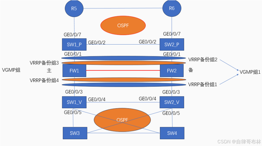
VRF交换机和防火墙的路由交互配置
防火墙和VRF交换机各自建立一个VRRP组,且两个组之间不想管,但相互对称。
防火墙视角:
去往内部的流量,vFW路由的下一跳为交换机的VRRP备份组3的虚拟IP地址,当Master设备存在时,由
Master设备进行回复。
而当Master设备故障时,或者Master设备连接防火墙的链路故障时,VRF交换机会将Master角色进行
切换。而防火墙因为感知到接口down,也会进行主备切换。
接下来,就又备份防火墙进行数据发送,访问的下一跳还是VRRP备份组3的虚拟IP地址
VRF交换机视角:
如果流量正常来到Master设备上,将由Master设备进行路由查找,请求下一跳地址的信息,即VRRP备份
组1的虚拟IP地址,正常情况又Active设备回复
如果流量没有正常来到Master设备,即可能因为Master设备故障,那么此时不管是VRF交换机还是防火
墙都会进行主备切换。且流量还是正常转发。
如果Master路由器的下游设备链路故障,流量不得已到达Backup,但是此时Master设备还是存在的,
此时Backup设备无法通过三层转发机制转发流量,只能通过二层转发机制,将流量引导到Master设备上,此
时报文转发路径为Backup--->Master--->vFW
想要实现上述效果,需要让两台防火墙和虚拟出来的两台VRF交换机的数据转发路径同属于一个广 播域,即使用相同的VLAN和网段信息。
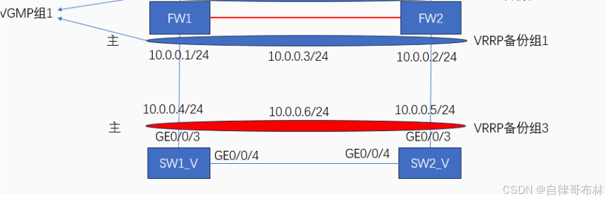
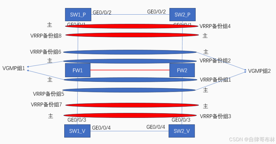
FW1为主
VRRP备份组1---VRRP备份组5
VRRP备份组3---VRRP备份组7

FW2为主
VRRP备份组2---VRRP备份组6
VRRP备份组4---VRRP备份组8

VRRP备份组1:VRF使用,SW1为Master,SW2为Backup
VLAN 401---10.40.1.0/24
SW1:10.40.1.1/24
SW2:10.40.1.2/24
虚拟地址:10.40.1.100
VRRP备份组2:VRF使用,SW2为Master,SW1为Backup
VLAN 402---10.40.2.0/24
SW1:10.40.2.1/24
SW2:10.40.2.2/24
虚拟地址:10.40.2.100
VRRP备份组3:Public使用,SW1为Master,SW2为Backup
VLAN 403---10.40.3.0/24
SW1:10.40.3.1/24
SW2:10.40.3.2/24
虚拟地址:10.40.3.100
VRRP备份组4:Public使用,SW2为Master,SW1为Backup
VLAN 404---10.40.4.0/24
SW1:10.40.4.1/24
SW2:10.40.4.2/24
虚拟地址:10.40.4.100


VRRP备份组5:防火墙使用,FW1为Master,FW2为Backup
VLAN 401---10.40.1.0/24
FW1:10.40.1.10/24
FW2:10.40.1.20/24
虚拟地址:10.40.1.200
VRRP备份组6:防火墙使用,FW2为Master,FW1为Backup
VLAN 402---10.40.2.0/24
FW1:10.40.2.10/24
FW2:10.40.2.20/24
虚拟地址:10.40.2.200
VRRP备份组7:防火墙使用,FW1为Master,FW2为Backup
VLAN 403---10.40.3.0/24
FW1:10.40.3.10/24
FW2:10.40.3.20/24
虚拟地址:10.40.3.200
VRRP备份组8:防火墙使用,FW2为Master,FW1为Backup
VLAN 404---10.40.4.0/24
FW1:10.40.4.10/24
FW2:10.40.4.20/24
虚拟地址:10.40.4.200
SW1、SW2配置
[SW1-Vlanif401]ip binding vpn-instance VRF
[SW1-Vlanif401]ip address 10.40.1.1 24
[SW1-Vlanif401]vrrp vrid 1 virtual-ip 10.40.1.100
[SW1-Vlanif401]vrrp vrid 1 priority  120
[SW1-Vlanif401]vrrp vrid 1 preempt-mode  timer  delay 60
[SW1-Vlanif401]vrrp vrid  1 track  interface  GigabitEthernet 0/0/3 reduced 30

[SW1-Vlanif402]ip binding vpn-instance VRF
[SW1-Vlanif402]ip address 10.40.2.1 24
[SW1-Vlanif402]vrrp vrid 2 virtual-ip 10.40.2.100


[SW1]int Vlanif 403
[SW1-Vlanif403]ip address 10.40.3.1 24
[SW1-Vlanif403]vrrp vrid 3 virtual-ip 10.40.3.100
[SW1-Vlanif403]vrrp vrid 3 priority  120
[SW1-Vlanif403]vrrp vrid 3 preempt-mode timer delay 60
[SW1-Vlanif403]vrrp vrid 3 track int g 0/0/1 reduced 30
[SW1]int Vlanif 404
[SW1-Vlanif404]ip address 10.40.4.1 24
[SW1-Vlanif404]vrrp vrid 4 virtual-ip 10.40.4.100


[SW1]ip route-static vpn-instance VRF 0.0.0.0 0 10.40.1.200
[SW1]ip route-static vpn-instance VRF 0.0.0.0 0 10.40.2.200 preference 70
[SW1]ip route-static 192.168.0.0 16 10.40.3.200
[SW1]ip route-static 192.168.0.0 16 10.40.4.200 preference 70


[SW2-Vlanif401]ip binding vpn-instance VRF
[SW2-Vlanif401]ip address 10.40.1.2 24
[SW2-Vlanif401]vrrp vrid 1 virtual-ip 10.40.1.100

[SW2-Vlanif402]ip binding vpn-instance VRF
[SW2-Vlanif402]ip address 10.40.2.2 24
[SW2-Vlanif402]vrrp vrid 2 virtual-ip 10.40.2.100
[SW2-Vlanif402]vrrp vrid 2 priority  120
[SW2-Vlanif402]vrrp vrid 2 preempt-mode  timer delay 60
[SW2-Vlanif402]vrrp vrid 2 track interface GigabitEthernet 0/0/3 reduced 30

[SW2]int Vlanif 403
[SW2-Vlanif403]ip address 10.40.3.2 24
[SW2-Vlanif403]vrrp vrid 3 virtual-ip 10.40.3.100
[SW2]int Vlanif 404
[SW2-Vlanif404]ip address 10.40.4.2 24
[SW2-Vlanif404]vrrp vrid 4 virtual-ip 10.40.4.100
[SW2-Vlanif404]vrrp vrid 4 priority 120
[SW2-Vlanif404]vrrp vrid 3 preempt-mode timer delay 60
[SW2-Vlanif404]vrrp vrid 3 track int g 0/0/3 reduced 30


[SW2]ip route-static vpn-instance VRF 0.0.0.0 0 10.40.2.200
[SW2]ip route-static vpn-instance VRF 0.0.0.0 0 10.40.1.200 preference 70
[SW2]ip route-static 192.168.0.0 16 10.40.4.200
[SW2]ip route-static 192.168.0.0 16 10.40.3.200 preference 70
FW1、FW2配置
FW1的配置
[FW1]int g 1/0/0
[FW1-GigabitEthernet1/0/0]ip add 10.10.10.1 30
[FW1]int g 1/0/2.401
[FW1-GigabitEthernet1/0/2.401]ip address 10.40.1.10 24
[FW1-GigabitEthernet1/0/2.401]vlan-type dot1q 401
[FW1]int g 1/0/2.402
[FW1-GigabitEthernet1/0/2.402]ip address 10.40.2.10 24
[FW1-GigabitEthernet1/0/2.402]vlan-type dot1q 402
[FW1]int g 1/0/3.403
[FW1-GigabitEthernet1/0/3.403]ip address 10.40.3.10 24
[FW1-GigabitEthernet1/0/3.403]vlan-type dot1q 403
[FW1-GigabitEthernet1/0/3.403]int g 1/0/3.404
FW1-GigabitEthernet1/0/3.404]ip address 10.40.4.10 24
[FW1-GigabitEthernet1/0/3.404]vlan-type dot1q 404


[FW1]firewall zone trust
[FW1-zone-trust]add interface GigabitEthernet 1/0/2.401
[FW1-zone-trust]add interface GigabitEthernet 1/0/2.402

[FW1]firewall zone untrust
[FW1-zone-untrust]add interface GigabitEthernet 1/0/3.403
[FW1-zone-untrust]add interface GigabitEthernet 1/0/3.404

[FW1]firewall zone  dmz
[FW1-zone-dmz]add interface GigabitEthernet 1/0/0

[FW1-GigabitEthernet1/0/2.401]vrrp vrid 5 virtual-ip 10.40.1.200 active
[FW1-GigabitEthernet1/0/2.402]vrrp vrid 6 virtual-ip 10.40.2.200 standby
[FW1-GigabitEthernet1/0/3.403]vrrp vrid 7 virtual-ip 10.40.3.200 active
[FW1-GigabitEthernet1/0/3.404]vrrp vrid 8 virtual-ip 10.40.4.200 standby

[FW1]hrp  mirror  session  enable
[FW1]hrp interface GigabitEthernet 1/0/0 remote 10.10.10.2
[FW1]hrp enable

HRP_S[FW1]ip route-static 0.0.0.0 0 10.40.3.100
HRP_M[FW1]ip route-static 0.0.0.0 0 10.40.4.100 preference 70

HRP_M[FW1]ip route-static 192.168.0.0 16 10.40.1.100
HRP_M[FW1]ip route-static 192.168.0.0 16 10.40.2.100 preference 70


HRP_M[FW1]security-policy (+B)
HRP_M[FW1-policy-security]rule name  t_to_u (+B)
HRP_M[FW1-policy-security-rule-t_to_u]source-zone trust  (+B)
HRP_M[FW1-policy-security-rule-t_to_u]destination-zone untrust  (+B)
HRP_M[FW1-policy-security-rule-t_to_u]source-address 192.168.0.0 16 (+B)
HRP_M[FW1-policy-security-rule-t_to_u]action permit  (+B)
FW2的配置
[FW2]int g 1/0/2.401
[FW2-GigabitEthernet1/0/2.401]ip address 10.40.1.20 24
[FW2-GigabitEthernet1/0/2.401]vlan-type dot1q 401
[FW2-GigabitEthernet1/0/2.401]int g 1/0/2.402
[FW2-GigabitEthernet1/0/2.402]ip address 10.40.2.20 24
[FW2-GigabitEthernet1/0/2.402]vlan-type dot1q 402
[FW2-GigabitEthernet1/0/2.402]int g 1/0/3.403
[FW2-GigabitEthernet1/0/3.403]ip address 10.40.3.20 24
[FW2-GigabitEthernet1/0/3.403]vlan-type dot1q 403
[FW2-GigabitEthernet1/0/3.403]int g 1/0/3.404
[FW2-GigabitEthernet1/0/3.404]ip address 10.40.4.20 24
[FW2-GigabitEthernet1/0/3.404]vlan-type dot1q  404


[FW2]firewall zone trust
[FW2-zone-trust]add int g 1/0/2.401
[FW2-zone-trust]add int g 1/0/2.402

[FW2]firewall zone  untrust
[FW2-zone-untrust]add int g 1/0/3.403
[FW2-zone-untrust]add int g 1/0/3.404

[FW2]firewall zone dmz
[FW2-zone-dmz]add int g 1/0/0


[FW2]int g 1/0/2.401
[FW2-GigabitEthernet1/0/2.401]vrrp vrid 5 virtual-ip 10.40.1.200 standby
[FW2]int g 1/0/2.402
[FW2-GigabitEthernet1/0/2.402]vrrp vrid 6 virtual-ip 10.40.2.200 active
[FW2]int g 1/0/3.403
[FW2-GigabitEthernet1/0/3.403]vrrp vrid 7 virtual-ip 10.40.3.200 standby
[FW2]int g 1/0/3.404
[FW2-GigabitEthernet1/0/3.404]vrrp vrid 8 virtual-ip 10.40.4.200 active


[FW2]hrp mirror session  enable
[FW2]hrp interface GigabitEthernet 1/0/0 remote 10.10.10.1
[FW2]hrp enable


HRP_S[FW2]ip route-static 0.0.0.0 0 10.40.3
HRP_S[FW2]ip route-static 0.0.0.0 0 10.40.3.100 preference 70
HRP_S[FW2]ip route-static 192.168.0.0 16 10.40.2.100
HRP_S[FW2]ip route-static 192.168.0.0 16 10.40.1.100 preference 70
核心到边界配置
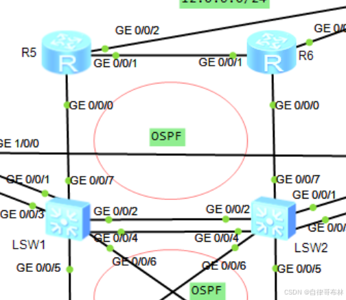
SW1-SW2:VLAN 201 --- 10.20.1.0/24
SW1-R5:VLAN 105 ---- 10.10.5.0/24
SW2-R6:VLAN 206 ---- 10.20.6.0/24
R5-R6: ---- 10.56.0.0/24
SW1
[SW1]interface Vlanif 105
[SW1-Vlanif105]ip address 10.10.5.1 24
[SW1]interface Vlanif 201
[SW1-Vlanif201]ip address 10.20.1.1 24
[SW1]ospf 2 router-id 1.1.1.1
[SW1-ospf-2]area 0
[SW1-ospf-2-area-0.0.0.0]network 10.20.1.1 0.0.0.0
[SW1-ospf-2-area-0.0.0.0]network 10.20.5.1 0.0.0.0
SW2
[SW2]interface Vlanif 201
[SW2-Vlanif201]ip address 10.20.1.2 24
[SW2]interface Vlanif 206
[SW2-Vlanif206]ip address 10.10.6.2 24
[SW2-ospf-2-area-0.0.0.0]network 10.20.6.2 0.0.0.0
[SW2-ospf-2-area-0.0.0.0]network 10.20.1.2 0.0.0.0
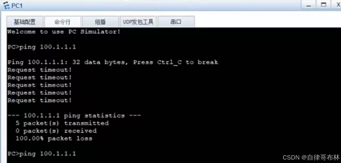
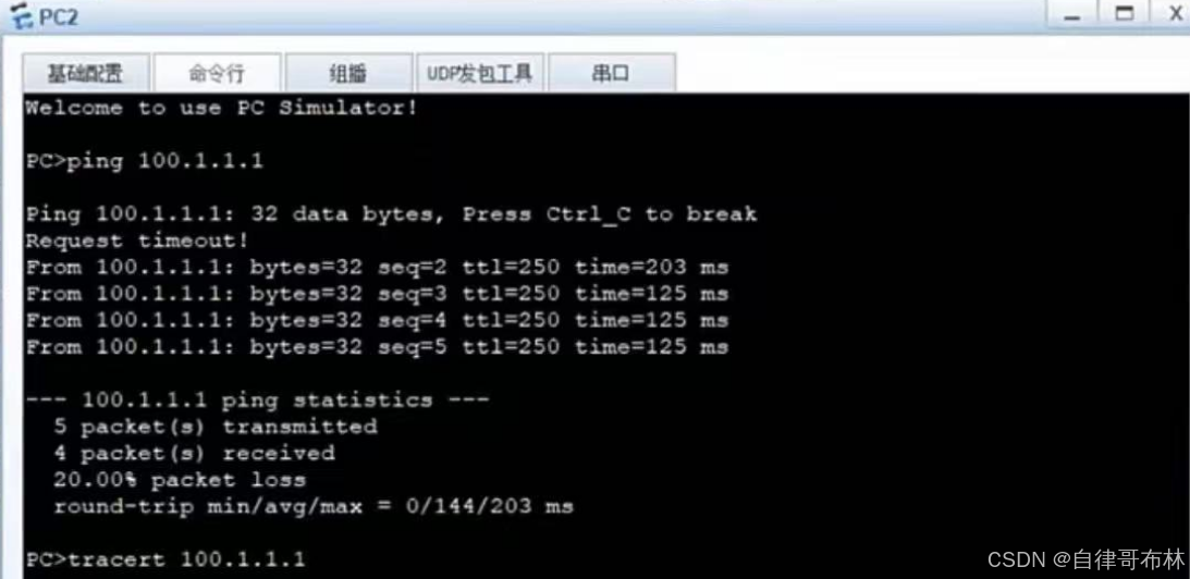
检验结果


 被折叠的 条评论
为什么被折叠?
被折叠的 条评论
为什么被折叠?
 到【灌水乐园】发言


