


之前介绍过UE_Visibility Buffer & Deferred Material,现在我们来看一下Visibility Buffer渲染架构的具体实现流程,本文主要参考使用图形大牛Wolfgang Engel的The filtered and culled Visibility Buffer技术介绍及代码来分析Visibility Buffer的主要架构与实现流程。
一、G-Buffer与Visibility Buffer
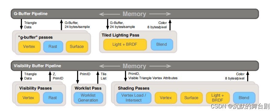
此处仅放一张管线图,具体优劣介绍见之前文章:UE_Visibility Buffer & Deferred Material。
此处大概介绍一下代码主要实现流程中包括以下两步:
- 使用常规绘制填充Visibility Buffer;
- 使用Visibility Buffer进行着色数据获取进行Shading;
当然了,其中还有好多过程性的渲染优化,此处就不展开了。
二、Visibility Buffer架构实现流程
2.1 Visibility Buffer格式说明
首先我们来看一下承载Visibility Buffer需要的格式:每个三角形的Visibility Buffer使用的RenderTarget是RGBA8格式的纹理,其中存储了如下的一些信息:
-
1bit的Alpha-Masked信息: 用于指明当前面片是否alpha masking(alpha test)
-
8bit的drawID: 对应的是indirect draw call的id,这个id可以表明当前的面片属于哪个draw call,8bit就对应最多256个draw call
-
23bit的triangleID,: 这个表示的是当前面片在当前draw call中的偏移,是每个draw call中的局部ID
这个RT在调用ExecuteIndirect的时候完成填充,同时还会完成Depth Buffer的输出,每个ExecuteIndirect指令调用都会读取VB/IB以及Material Buffer(简称MB)
2.2 填充Visibility Buffer
首先说一下此处管线的mesh的数据只需要位置信息即可,其余的都可以通过绘制传进去。
我们来看一下顶点着色器的主要流程:
#ifdef VULKAN
	#extension GL_ARB_shader_draw_parameters : enable
#endif

STRUCT(VsInOpaque)
{
    DATA(float3, position, POSITION);
};

STRUCT(PsInOpaque)
{
	DATA(float4, position, SV_Position);
#if defined(VULKAN) || defined(ORBIS) || defined(PROSPERO) || defined(METAL)
    DATA(FLAT(uint), drawId, TEXCOORD3);
#endif
};

PsInOpaque VS_MAIN( VsInOpaque In, SV_InstanceID(uint) instanceId )
{
	INIT_MAIN;
	PsInOpaque Out;
	Out.position = mul(Get(transform)[VIEW_CAMERA].mvp, float4(In.position.xyz, 1.0f));
#ifdef VULKAN
	Out.drawId = gl_DrawIDARB;
#elif defined(ORBIS) || defined(PROSPERO) || defined(METAL)
	Out.drawId = instanceId;
#endif
	RETURN(Out);
}
片元着色器主要实现流程如下:
STRUCT(PsInOpaque)
{
	DATA(float4, position, SV_Position);
#if defined(VULKAN) || defined(ORBIS) || defined(PROSPERO) || defined(METAL)
    DATA(FLAT(uint), drawId, TEXCOORD3);
#endif
};

float4 unpackUnorm4x8(uint p)
{
	return float4(float(p & 0x000000FF) / 255.0,
				  float((p & 0x0000FF00) >> 8) / 255.0,
				  float((p & 0x00FF0000) >> 16) / 255.0,
				  float((p & 0xFF000000) >> 24) / 255.0);
}

uint calculateOutputVBID(uint drawID, uint primitiveID)
{
    return  ((drawID << DRAW_ID_LOW_BIT) & DRAW_ID_MASK) |
			((primitiveID << PRIM_ID_LOW_BIT) & PRIM_ID_MASK);
}

float4 PS_MAIN( PsInOpaque In, SV_PrimitiveID(uint) primitiveId )
{
    INIT_MAIN;
    float4 Out;
    Out = unpackUnorm4x8(calculateOutputVBID(getDrawID(), primitiveId));
    RETURN(Out);
}
其中主要使用位置信息来记录Alpha-Masked、drawID、triangleID的数据,先将其压缩为uint,再转为float4输出到RGBA8缓冲区中。
经过填充后,可以获得以下数据:

同时还会生成一个深度图:

2.3 计算Shading
Visibility Buffer跟Depth Buffer填充完成之后,就可以考虑进行Shading操作了。不过在此之前,我们首先来看一下除了上边生成的像素级可见数据外,我们还需要哪些数据:
- Vertex Buffer: 中的数据布局包含:Position,Texture coordinates,Normals,Tangents。(当然了其他变种做法也可以把重心用16 bits表示放 R32G32_UINT 纹理中);
- **Index Buffer:**存储对应的索引数据,在shading中进行对应的查找索引用到;
- Material Buffer: shading用到的最后一项数据为texture id或者material buffer,这个数据对应的是场景中的大量material数据。
总的来说就是:在光照着色阶段,只需要根据InstanceID和PrimitiveID从全局的Vertex Buffer中索引到相关三角形的信息;进一步地,根据像该素的重心坐标,对Vertex Buffer内的顶点信息(UV,Tangent Space等)进行插值得到逐像素信息;再进一步地,根据MaterialID去索引相关的材质信息,执行贴图采样等操作,并输入到光照计算环节最终完成着色,有时这类方法也被称为Deferred Texturing。
下边我们来看一下具体的实现:
顶点着色器如下(简单三角形绘制):
// 加载每个像素的绘制/三角形Id并重建插值的顶点数据。
STRUCT(VSOutput)
{
	DATA(float4, position, SV_Position);
	DATA(float2, screenPos, TEXCOORD0);
#line 30
};

// Vertex shader
VSOutput VS_MAIN( uint vertexId : SV_VERTEXID )
{
	//生成一个全屏三角形使用当前的vertexId来自动计算顶点划分。 这种方法避免使用顶点/索引缓冲区来生成一个全屏四边形。
	//INIT_MAIN;
	VSOutput result;
	result.position.x = (vertexId == 2 ? 3.0 : -1.0);
	result.position.y = (vertexId == 0 ? -3.0 : 1.0);
	result.position.zw = float2(0, 1);
	result.screenPos = result.position.xy;
	return (result);
}
接下来重点来了,最重要的片元着色器如下:
STRUCT(VSOutput)
{
	DATA(float4, position, SV_Position);
	DATA(float2, screenPos, TEXCOORD0);
};

struct DerivativesOutput
{
	float3 db_dx;
	float3 db_dy;
};

struct TransparentNodeOIT
{
	uint triangleData;
	uint next;
};

struct NodeFinalOIT
{
	float3 color;
	float  depth;
	uint   next;
};

// 从投影的屏幕空间顶点计算三角形的偏导数
DerivativesOutput computePartialDerivatives(float2 v[3])
{
	DerivativesOutput result;
	float d = 1.0 / determinant(f2x2(v[2] - v[1], v[0] - v[1]));
	result.db_dx = float3(v[1].y - v[2].y, v[2].y - v[0].y, v[0].y - v[1].y) * d;
	result.db_dy = float3(v[2].x - v[1].x, v[0].x - v[2].x, v[1].x - v[0].x) * d;

	return result;
}

// 使用偏导数在点d插入顶点属性的辅助函数
float3 interpolateAttribute(float3x3 attributes, float3 db_dx, float3 db_dy, float2 d)
{
	float3 attribute_x = mul(db_dx, attributes);
	float3 attribute_y = mul(db_dy, attributes);
	float3 attribute_s = getRow0(attributes);

	return (attribute_s + d.x * attribute_x + d.y * attribute_y);
}

float interpolateAttribute(float3 attributes, float3 db_dx, float3 db_dy, float2 d)
{
	float attribute_x = dot(attributes, db_dx);
	float attribute_y = dot(attributes, db_dy);
	float attribute_s = attributes[0];

	return (attribute_s + d.x * attribute_x + d.y * attribute_y);
}

struct GradientInterpolationResults
{
	float2 interp;
	float2 dx;
	float2 dy;
};

// 使用偏导数插值2D属性,生成纹理采样的dx和dy。
GradientInterpolationResults interpolateAttributeWithGradient(f3x2 attributes, float3 db_dx, float3 db_dy, float2 d, float2 pTwoOverRes)
{
	float3 attr0 = getRow0(attributes);
	float3 attr1 = getRow1(attributes);
	float2 attribute_x = float2(dot(db_dx, attr0), dot(db_dx, attr1));
	float2 attribute_y = float2(dot(db_dy, attr0), dot(db_dy, attr1));
	float2 attribute_s = getCol0(attributes);

	GradientInterpolationResults result;
	result.dx = attribute_x * pTwoOverRes.x;
	result.dy = attribute_y * pTwoOverRes.y;
	result.interp = (attribute_s + d.x * attribute_x + d.y * attribute_y);
	return result;
}

float depthLinearization(float depth, float near, float far)
{
	return (2.0 * near) / (far + near - depth * (far - near));
}

// Static descriptors
#if(SAMPLE_COUNT > 1)
	RES(Tex2DMS(float4, SAMPLE_COUNT), vbTex, UPDATE_FREQ_NONE, t0, binding = 14);
#else
	RES(Tex2D(float4), vbTex, UPDATE_FREQ_NONE, t0, binding = 14);
#endif

RES(Buffer(uint),               headIndexBufferSRV, UPDATE_FREQ_NONE, t30, binding = 15);
RES(Buffer(TransparentNodeOIT), vbDepthLinkedListSRV, UPDATE_FREQ_NONE, t31, binding = 16);

RES(Tex2D(float), shadowMap, UPDATE_FREQ_NONE, t101, binding = 18);

#if defined(METAL) || defined(ORBIS) || defined(PROSPERO)
	RES(Tex2D(float4), diffuseMaps[MATERIAL_BUFFER_SIZE],  UPDATE_FREQ_NONE, t0, binding = 19);
	RES(Tex2D(float4), normalMaps[MATERIAL_BUFFER_SIZE],   UPDATE_FREQ_NONE, t1, binding = 19 + MAX_TEXTURE_UNITS);
	RES(Tex2D(float4), specularMaps[MATERIAL_BUFFER_SIZE], UPDATE_FREQ_NONE, t2, binding = 19 + MAX_TEXTURE_UNITS * 2);
#else
	RES(Tex2D(float4), diffuseMaps[MATERIAL_BUFFER_SIZE],  space4, t0, binding = 19);
	RES(Tex2D(float4), normalMaps[MATERIAL_BUFFER_SIZE],   space5, t0, binding = 19 + MAX_TEXTURE_UNITS);
	RES(Tex2D(float4), specularMaps[MATERIAL_BUFFER_SIZE], space6, t0, binding = 19 + MAX_TEXTURE_UNITS * 2);
#endif

RES(ByteBuffer, vertexPos,           UPDATE_FREQ_NONE, t10, binding=0);
RES(ByteBuffer, vertexTexCoord,      UPDATE_FREQ_NONE, t11, binding=1);
RES(ByteBuffer, vertexNormal,        UPDATE_FREQ_NONE, t12, binding=2);
RES(ByteBuffer, vertexTangent,       UPDATE_FREQ_NONE, t13, binding=3);
RES(ByteBuffer, filteredIndexBuffer, UPDATE_FREQ_PER_FRAME, t14, binding=4);

RES(Buffer(uint), indirectMaterialBuffer,       UPDATE_FREQ_PER_FRAME, t15, binding=5);
RES(Buffer(uint), indirectDrawArgs[3],          UPDATE_FREQ_PER_FRAME, t17, binding=9);
RES(Buffer(MeshConstants), meshConstantsBuffer, UPDATE_FREQ_NONE, t16, binding=6);
RES(Buffer(LightData), lights,                  UPDATE_FREQ_NONE, t19, binding=11);

RES(ByteBuffer, lightClustersCount, UPDATE_FREQ_PER_FRAME, t20, binding=12);
RES(ByteBuffer, lightClusters,      UPDATE_FREQ_PER_FRAME, t21, binding=13);

RES(SamplerState, textureSampler, UPDATE_FREQ_NONE, s0, binding = 7);
RES(SamplerState, depthSampler, UPDATE_FREQ_NONE, s1, binding = 8);


//数据转换并进行着色
float4 tri_data_to_frag_color(float4 inPosition, float2 screenPos, uint drawID, uint triangleID, uint trans1_opaque0, uint alpha1_opaque0)
{
	// TODO: Inefficient
	uint materialIndex = GEOMSET_OPAQUE;
	materialIndex = materialIndex;
	if (alpha1_opaque0 == 1)
		materialIndex = GEOMSET_ALPHATESTED;
	if (trans1_opaque0 == 1)
		materialIndex = GEOMSET_TRANSPARENT;

	// 这是当前绘制批处理的起始顶点
	uint startIndexOffset = INDIRECT_DRAW_ARGUMENTS_STRUCT_OFFSET + 2;
	//uint startIndex = alpha1_opaque0 == 0 ?
	//	Get(indirectDrawArgs)[0][drawID * INDIRECT_DRAW_ARGUMENTS_STRUCT_NUM_ELEMENTS + startIndexOffset] :
	//	Get(indirectDrawArgs)[1][drawID * INDIRECT_DRAW_ARGUMENTS_STRUCT_NUM_ELEMENTS + startIndexOffset];
	uint startIndex = Get(indirectDrawArgs)[GEOMSET_OPAQUE][drawID * INDIRECT_DRAW_ARGUMENTS_STRUCT_NUM_ELEMENTS + startIndexOffset];
	if (alpha1_opaque0 == 1)
		startIndex = Get(indirectDrawArgs)[GEOMSET_ALPHATESTED][drawID * INDIRECT_DRAW_ARGUMENTS_STRUCT_NUM_ELEMENTS + startIndexOffset];
	if (trans1_opaque0 == 1)
		startIndex = Get(indirectDrawArgs)[GEOMSET_TRANSPARENT][drawID * INDIRECT_DRAW_ARGUMENTS_STRUCT_NUM_ELEMENTS + startIndexOffset];

	uint triIdx0 = (triangleID * 3 + 0) + startIndex;
	uint triIdx1 = (triangleID * 3 + 1) + startIndex;
	uint triIdx2 = (triangleID * 3 + 2) + startIndex;

	uint index0 = LoadByte(Get(filteredIndexBuffer), triIdx0 << 2);
	uint index1 = LoadByte(Get(filteredIndexBuffer), triIdx1 << 2);
	uint index2 = LoadByte(Get(filteredIndexBuffer), triIdx2 << 2);

	// 加载3个顶点的顶点数据
	float3 v0pos = asfloat(LoadByte4(Get(vertexPos), index0 * 12)).xyz;
	float3 v1pos = asfloat(LoadByte4(Get(vertexPos), index1 * 12)).xyz;
	float3 v2pos = asfloat(LoadByte4(Get(vertexPos), index2 * 12)).xyz;

	// 转换位置到裁剪空间
	float4 pos0 = mul(Get(transform)[VIEW_CAMERA].mvp, float4(v0pos, 1.0f));
	float4 pos1 = mul(Get(transform)[VIEW_CAMERA].mvp, float4(v1pos, 1.0f));
	float4 pos2 = mul(Get(transform)[VIEW_CAMERA].mvp, float4(v2pos, 1.0f));

	// 计算齐次坐标w的倒数,因为它会被用到很多次
	float3 one_over_w = 1.0f / float3(pos0.w, pos1.w, pos2.w);

	// 投影顶点位置来计算2D透视后的位置
	pos0 *= one_over_w[0];
	pos1 *= one_over_w[1];
	pos2 *= one_over_w[2];

	float2 pos_scr[3] = { pos0.xy, pos1.xy, pos2.xy };

	// 计算偏导数。 这对于插值每个像素的三角形属性是必要的。
	DerivativesOutput derivativesOut = computePartialDerivatives(pos_scr);

	// 计算从投影顶点0指向当前屏幕点的增量向量(d)
	float2 d = screenPos + -pos_scr[0];

	//为三角形的三个顶点插入1/w (one_over_w),使用重心坐标和delta向量
	float w = 1.0f / interpolateAttribute(one_over_w, derivativesOut.db_dx, derivativesOut.db_dy, d);

	//在这个屏幕点重构Z值,只执行必要的矩阵*向量乘法操作,涉及到计算Z
	float z = w * getElem(Get(transform)[VIEW_CAMERA].projection, 2, 2) + getElem(Get(transform)[VIEW_CAMERA].projection, 3, 2);

	//计算世界位置坐标:
    //首先,在这一点的投影坐标计算使用screenPos和计算的Z值在这一点。
    //然后,将透视投影坐标乘以逆视图投影矩阵(invVP)得到世界坐标
	float3 position = mul(Get(transform)[VIEW_CAMERA].invVP, float4(screenPos * w, z, w)).xyz;


	//纹理坐标插值,对纹理坐标应用透视校正
	f3x2 texCoords = make_f3x2_cols(
			unpack2Floats(LoadByte(Get(vertexTexCoord), index0 << 2)) * one_over_w[0],
			unpack2Floats(LoadByte(Get(vertexTexCoord), index1 << 2)) * one_over_w[1],
			unpack2Floats(LoadByte(Get(vertexTexCoord), index2 << 2)) * one_over_w[2]
	);

	// 插值纹理坐标和计算纹理采样的梯度与mipmapping支持
	GradientInterpolationResults results = interpolateAttributeWithGradient(texCoords, derivativesOut.db_dx, derivativesOut.db_dy, d, Get(twoOverRes));

	float linearZ = depthLinearization(z/w, Get(CameraPlane).x, Get(CameraPlane).y);
	float mip = pow(pow(linearZ, 0.9f) * 5.0f, 1.5f);

	float2 texCoordDX = results.dx * w * mip;
	float2 texCoordDY = results.dy * w * mip;
	float2 texCoord = results.interp * w;


	/LOAD///
	// 切线插值
	// 对切线应用透视分割
	float3x3 tangents = make_f3x3_rows(
			decodeDir(unpackUnorm2x16(LoadByte(Get(vertexTangent), index0 << 2))) * one_over_w[0],
			decodeDir(unpackUnorm2x16(LoadByte(Get(vertexTangent), index1 << 2))) * one_over_w[1],
			decodeDir(unpackUnorm2x16(LoadByte(Get(vertexTangent), index2 << 2))) * one_over_w[2]
	);

	float3 tangent = normalize(interpolateAttribute(tangents, derivativesOut.db_dx, derivativesOut.db_dy, d));

	//  BaseMaterialBuffer返回常量偏移值
	// 下面的值定义了一次绘制的间接绘制调用的最大数量。 这个值取决于场景中的子网格或单个对象的数量。 改变场景需要相应地改变这个值。
	// #define MAX_DRAWS_INDIRECT 300
	//
	// 这些值是用来指向材料数据的偏移量,这取决于几何形状的类型和剔除视图
	// #define MATERIAL_BASE_ALPHA0 0
	// #define MATERIAL_BASE_NOALPHA0 MAX_DRAWS_INDIRECT
	// #define MATERIAL_BASE_ALPHA1 (MAX_DRAWS_INDIRECT*2)
	// #define MATERIAL_BASE_NOALPHA1 (MAX_DRAWS_INDIRECT*3)
	uint materialBaseSlot = BaseMaterialBuffer(materialIndex, VIEW_CAMERA);

	// materialBaseSlot + drawID 可能的结果如下
	// 0 - 299 - shadow alpha
	// 300 - 599 - shadow no alpha
	// 600 - 899 - camera alpha
	uint materialID = Get(indirectMaterialBuffer)[materialBaseSlot + drawID];

	// 使用插值属性计算像素颜色
	// 从X和Y重建法线贴图Z

	// 从数组中获取纹理。
	float4 normalMapRG;
	float4 diffuseColor;
	float4 specularColor;
	BeginNonUniformResourceIndex(materialID, MAX_TEXTURE_UNITS);
		normalMapRG   = SampleGradTex2D(Get(normalMaps)[materialID],   Get(textureSampler), texCoord, texCoordDX, texCoordDY);
		diffuseColor  = SampleGradTex2D(Get(diffuseMaps)[materialID],  Get(textureSampler), texCoord, texCoordDX, texCoordDY);
		specularColor = SampleGradTex2D(Get(specularMaps)[materialID], Get(textureSampler), texCoord, texCoordDX, texCoordDY);
	EndNonUniformResourceIndex();

	float3 reconstructedNormalMap;
	reconstructedNormalMap.xy = normalMapRG.ga * 2.0f - 1.0f;
	reconstructedNormalMap.z = sqrt(1 - dot(reconstructedNormalMap.xy, reconstructedNormalMap.xy));

	//正常插值
	//对法线应用透视除法
	float3x3 normals = make_f3x3_rows(
		decodeDir(unpackUnorm2x16(LoadByte(Get(vertexNormal), index0 << 2))) * one_over_w[0],
		decodeDir(unpackUnorm2x16(LoadByte(Get(vertexNormal), index1 << 2))) * one_over_w[1],
		decodeDir(unpackUnorm2x16(LoadByte(Get(vertexNormal), index2 << 2))) * one_over_w[2]
	);
	float3 normal = normalize(interpolateAttribute(normals, derivativesOut.db_dx, derivativesOut.db_dy, d));

	// 从法线和切线计算顶点副法线
	float3 binormal = normalize(cross(tangent, normal));

	// 使用法线映射和切空间向量计算像素法线
	normal = reconstructedNormalMap.x * tangent + reconstructedNormalMap.y * binormal + reconstructedNormalMap.z * normal;

	// 漫射颜色
	float4 posLS = mul(Get(transform)[VIEW_SHADOW].vp, float4(position, 1.0f));

	float Roughness = clamp(specularColor.a, 0.05f, 0.99f);
	float Metallic = specularColor.b;

	float ao = 1.0f;

	bool isTwoSided = (alpha1_opaque0 == 1 || trans1_opaque0 == 1) && bool(Get(meshConstantsBuffer)[materialID].twoSided);
	bool isBackFace = false;

	float3 ViewVec = normalize(Get(camPos).xyz - position.xyz);

	//如果它是背面,这应该是< 0,但我们的网格的边缘法线是平滑的y
	if (isTwoSided && dot(normal, ViewVec) < 0.0f)
	{
		//法线反转
		normal = -normal;
		isBackFace = true;
	}

	float3 HalfVec = normalize(ViewVec - Get(lightDir).xyz);
	float3 ReflectVec = reflect(-ViewVec, normal);
	float NoV = saturate(dot(normal, ViewVec));

	float NoL = dot(normal, -Get(lightDir).xyz);

	// 处理双面材质
	NoL = (isTwoSided ? abs(NoL) : saturate(NoL));

	float3 shadedColor = f3(0.0f);

	float3 F0 = specularColor.xyz;
	float3 DiffuseColor = diffuseColor.xyz;
	float shadowFactor = 1.0f;
	float fLightingMode = saturate(float(Get(lightingMode)));

	shadedColor = calculateIllumination(
		    normal,
		    ViewVec,
			HalfVec,
			ReflectVec,
			NoL,
			NoV,
			Get(camPos).xyz,
			Get(esmControl),
			Get(lightDir).xyz,
			posLS,
			position,
			Get(shadowMap),
			DiffuseColor,
			F0,
			Roughness,
			Metallic,
			Get(depthSampler),
			isBackFace,
			fLightingMode,
			shadowFactor);

	shadedColor = shadedColor * Get(lightColor).rgb * Get(lightColor).a * NoL * ao;

	// 点光源
	// 找到当前像素的光簇
	uint2 clusterCoords = uint2(floor((screenPos * 0.5f + 0.5f) * float2(LIGHT_CLUSTER_WIDTH, LIGHT_CLUSTER_HEIGHT)));

	uint numLightsInCluster = LoadByte(Get(lightClustersCount), LIGHT_CLUSTER_COUNT_POS(clusterCoords.x, clusterCoords.y) << 2);

	// 光积累的贡献
	for (uint j = 0; j < numLightsInCluster; ++j)
	{
		uint lightId = LoadByte(Get(lightClusters), LIGHT_CLUSTER_DATA_POS(j, clusterCoords.x, clusterCoords.y) << 2);

		shadedColor += pointLightShade(
		normal,
		ViewVec,
		HalfVec,
		ReflectVec,
		NoL,
		NoV,
		Get(lights)[lightId].position.xyz,
		Get(lights)[lightId].color.xyz,
		Get(camPos).xyz,
		Get(lightDir).xyz,
		posLS,
		position,
		DiffuseColor,
		F0,
		Roughness,
		Metallic,
		isBackFace,
		fLightingMode);
	}

	float ambientIntencity = 0.05f;
	float3 ambient = diffuseColor.xyz * ambientIntencity;

	return float4(shadedColor + ambient, linearZ);
}

float4 PS_MAIN( VSOutput In, SV_SampleIndex(uint) i )
{
	INIT_MAIN;
	//从渲染目标加载可见性缓冲原始打包的float4数据
#if(SAMPLE_COUNT > 1)
	float4 visRaw = LoadTex2DMS(Get(vbTex), Get(depthSampler), uint2(In.position.xy), i);
#else
	float4 visRaw = LoadTex2D(Get(vbTex), Get(depthSampler), uint2(In.position.xy), 0);
#endif
	// 将float4渲染目标数据解压为uint以提取数据
	uint alphaBit_transBit_drawID_triID = packUnorm4x8(visRaw);

	uint opaqueShaded = 0;
	uint transparentShaded = 0;

	float VisDepth = 1.0f;
	float3 OutColor = float3(0, 0, 0);

	// 如果这个像素不包含三角形数据,则提前退出
	if (alphaBit_transBit_drawID_triID != ~0u)
	{
		// 提取数据
		uint drawID = (alphaBit_transBit_drawID_triID >> DRAW_ID_LOW_BIT) & 0x000000FF;
		uint triangleID = (alphaBit_transBit_drawID_triID & PRIM_ID_MASK);
		uint alpha1_opaque0 = (alphaBit_transBit_drawID_triID >> ALPH_IS_LOW_BIT);

		float4 VisColor = tri_data_to_frag_color(In.position, In.screenPos, drawID, triangleID, 0, alpha1_opaque0);
		OutColor = VisColor.xyz;
		VisDepth = VisColor.w;

		opaqueShaded = 1;
	}

	uint2 pixelAddr = uint2(In.position.xy);
	uint scrW = Get(screenWidth);
	uint bufferIdx = pixelAddr.y * scrW + pixelAddr.x;
	uint nodeIdx = Get(headIndexBufferSRV)[bufferIdx];

	if (nodeIdx != OIT_HEAD_INVALID)
	{
		uint count = 0;
		NodeFinalOIT fragments[OIT_MAX_FRAG_COUNT];

		// 积累透明像素颜色数据
		while (nodeIdx != OIT_HEAD_INVALID)
		{
			if (count >= OIT_MAX_FRAG_COUNT)
			{
				break;
			}

			TransparentNodeOIT node = Get(vbDepthLinkedListSRV)[nodeIdx];

			uint nodeNextIdx = node.next;
			uint nodeTriangleData = node.triangleData;

			uint nodeDrawID = (nodeTriangleData >> DRAW_ID_LOW_BIT) & 0x000000FF;
			uint nodeTriangleID = (nodeTriangleData & PRIM_ID_MASK);
			float4 nodeColorData = tri_data_to_frag_color(In.position, In.screenPos, nodeDrawID, nodeTriangleID, 1, 0);

			// 手动进行深度测试
			if (nodeColorData.w < VisDepth)
			{
				fragments[count].color = nodeColorData.xyz;
				fragments[count].depth = nodeColorData.w;
				fragments[count].next  = nodeNextIdx;

				++count;
			}

			nodeIdx = nodeNextIdx;
		}

		// May be no fragments left after manual depth cull
		if (count > 0)
		{
			// Insertion sort
			for (uint j = 1; j < count; ++j)
			{
				NodeFinalOIT insert = fragments[j];
				uint k = j;

				while (k > 0)
				{
					if (insert.depth <= fragments[k - 1].depth)
					{
						break;
					}

					fragments[k] = fragments[k - 1];
					--k;
				}

				fragments[k] = insert;
			}

			// Blending
			float3 TransparentColor = fragments[0].color;
			float alpha = Get(transAlpha);
			for (uint l = 1; l < count; ++l)
			{
				TransparentColor = lerp(TransparentColor, fragments[l].color, alpha);
			}
			OutColor = lerp(OutColor, TransparentColor, alpha);

			transparentShaded = 1;
		}
	}
	else if (opaqueShaded == 0)
	{
		discard;
	}

	float OutAlpha = (transparentShaded == 1 && opaqueShaded == 0) ? Get(transAlpha) : 1.0f;
	RETURN(float4(OutColor, OutAlpha));
}
上边片元着色器中可以主要看一下tri_data_to_frag_color函数:此函数是将Visibility Buffer中数据进行转换并索引真实场景数据进行着色的全部流程。
其他过程参照注释即可。
经过上述计算可以得到:

三、Visibility Buffer总结
Visibility Buffer 与 G-Buffer的具体对比可以参照以前文章。具体不再赘述,下边主要来看一下Visibility Buffer的优点
3.1 内存带宽
Visibility Buffer方案在带宽消耗上有更大的优势,这一点在高分辨率屏幕,或者在一些高速存储器尺寸受限的情况下(比如只能支持到32位的RT,甚至只能支持屏幕中的部分区域的使用如TBDR架构下的硬件条件)更为明显。
3.2 内存访问模式
shading pass中,我们会根据visibility buffer的数据获得各个像素对应的triangle ID,此时并没有发生顶点属性的读取逻辑,对index buffer以及vertex buffer的真正的读取过程跟一个普通的draw call的实现逻辑差不多,不过这个draw call是覆盖全屏幕的,且数据是全屏幕连续的,并且仅发生一次,而这种数据获取的方式是现代GPU架构friendly的,经过测试发现,这种模式下,对于贴图、VB/IB数据的获取,在L2上可以达到99%的命中率,从而使得整个着色过程十分的高效。


 被折叠的 条评论
为什么被折叠?
被折叠的 条评论
为什么被折叠?
 到【灌水乐园】发言


