


 这篇博客主要介绍了GAMES101作业中关于光线追踪的两个关键函数:rayTriangleIntersect()和Render()的实现。在rayTriangleIntersect()中,遵循PPT中的公式并检查交点是否在三角形内。Render()函数涉及多个坐标空间的转换,包括Raster space到NDC space,再到Screen Space,然后是Camera space,并考虑了图像宽高比和相机的fov。博客提供了详细的转换公式和代码实现,最终展示了渲染效果。
本次作业中,有2个函数需要修改:

其中第二个比较简单,我们先讲第二个。
rayTriangleIntersect():在Triangle.hpp中
按照PPT公式来实现即可。
需要注意的点是:公式中的b1 b2 (1-b1-b2)分别代表了三角形中心坐标中的α,β,γ,计算完之后,除了要验证 t 是否为正, 还要验证b1 b2 (1-b1-b2)是否在三角形内!

实现代码如下:
// TODO: Implement this function that tests whether the triangle
// that's specified bt v0, v1 and v2 intersects with the ray (whose
// origin is *orig* and direction is *dir*)
// Also don't forget to update tnear, u and v

bool rayTriangleIntersect(const Vector3f& v0, const Vector3f& v1, const Vector3f& v2, const Vector3f& orig,
                          const Vector3f& dir, float& tnear, float& u, float& v)
{
    Vector3f e1 = v1 - v0;
    Vector3f e2 = v2 - v0;
    Vector3f s = orig - v0;
    Vector3f s1 = crossProduct(dir, e2);
    Vector3f s2 = crossProduct(s, e1);

    float dividend = dotProduct(s1, e1);
    Vector3f divisor = {
        dotProduct(s2, e2),
        dotProduct(s1, s),
        dotProduct(s2, dir)
    };

    Vector3f result = divisor / dividend;

    tnear = result.x;
    u = result.y;
    v = result.z;

    // check: t >= 0 and b1,b2,(1-b1-b2) inside triangle
    if (tnear > 0 && u >= 0 && v >= 0 && (1.0f-u-v) >= 0) return true;

    return false;
}有参考:GAMES101-作业5_StrangerMQ的博客-优快云博客_games101 作业5
Render():在Renderer.cpp中
详细解释参见(英文阅读注意!):Ray-Tracing: Generating Camera Rays (Generating Camera Rays)
我这里讲一些重要的步骤:
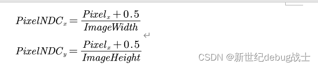
1. 首先,将Raster space转换为NDC space(范围[0,1]),使用如下公式:
转换前后的示意图:
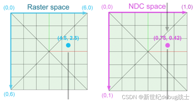
转换前 VS 转换后
2. 然后,将NDC space转换为Screen Space,使用如下公式:
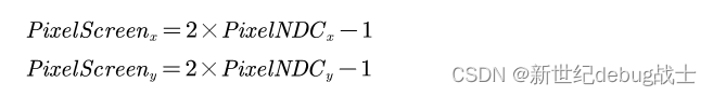
但是请注意,对于这个等式,PixelScreen_y对于本应该位于 x 轴上方的y值为负数,对于本应该位于下方的y值则为正数,例如:
① 在NDC space中,y=0.4,转换后y'=2y-1=-0.2,位于x轴下方。
② 在在NDC space中,y=0.6,转换后y'=2y-1=0.2,位于x轴上方。
我们可以使用如下的公式来修正这个问题:
![]()
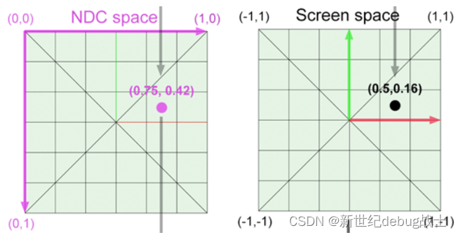
转换前 VS 转换后
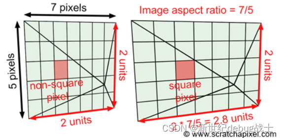
3. 将Screen space转换为Camera space
由于图像的宽高不同,屏幕的总像素空间并不是标准正方形。为了纠正这个问题,我们需要通过Image Aspect Ratio沿 x 轴缩放图像平面,该比例值可以通过将图像的height / width(以像素为单位)计算得出。
综上,x值的最终范围应为[-Image Aspect Ratio, Image Aspect Ratio]。
变换公式如下:

以上变换过程的示意图:
然后我们再考虑相机的fov:
这个操作改变了我们看到的场景的多少,相当于放大(当fov减小时我们看到的场景更少,但像素长宽不变,遂相当于放大)和缩小(当fov增加时)。总之,我们可以根据角度 α 来定义相机的视野,并将屏幕像素坐标乘以tan(α/2)。
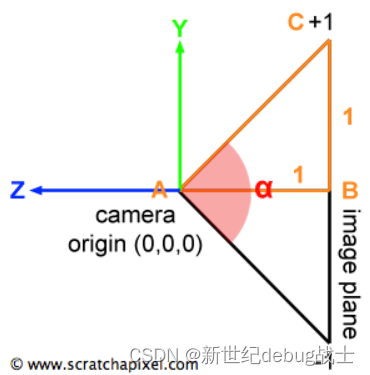
使用公式如下:

最终,这个点已经处于camera space中。 当camera在其默认位置时,camera坐标系和世界坐标系是对齐的。 该点位于距离camera原点 1 个单位的图像平面上,但请记住,相机也沿负 z 轴对齐。 因此我们可以将像素在图像平面上的最终坐标(3D)表示为:

最终实现代码如下:
// [comment]
// The main render function. This where we iterate over all pixels in the image, generate
// primary rays and cast these rays into the scene. The content of the framebuffer is
// saved to a file.
// [/comment]
void Renderer::Render(const Scene& scene)
{
std::vector<Vector3f> framebuffer(scene.width * scene.height);
float scale = std::tan(deg2rad(scene.fov * 0.5f));
float imageAspectRatio = scene.width / (float)scene.height;
// Use this variable as the eye position to start your rays.
Vector3f eye_pos(0);
int m = 0;
for (int j = 0; j < scene.height; ++j)
{
for (int i = 0; i < scene.width; ++i)
{
// generate primary ray direction
// TODO: Find the x and y positions of the current pixel to get the direction
// vector that passes through it.
// Also, don't forget to multiply both of them with the variable *scale*, and
// x (horizontal) variable with the *imageAspectRatio*
float x = (2 * (i + 0.5) / (float)scene.width - 1) * imageAspectRatio * scale;
float y = (1 - 2 * (j + 0.5) / (float)scene.height) * scale;
Vector3f dir = Vector3f(x, y, -1); // Don't forget to normalize this direction!
dir = normalize(dir);
framebuffer[m++] = castRay(eye_pos, dir, scene, 0);
}
UpdateProgress(j / (float)scene.height);
}
// save framebuffer to file
FILE* fp = fopen("binary.ppm", "wb");
(void)fprintf(fp, "P6\n%d %d\n255\n", scene.width, scene.height);
for (auto i = 0; i < scene.height * scene.width; ++i) {
static unsigned char color[3];
color[0] = (char)(255 * clamp(0, 1, framebuffer[i].x));
color[1] = (char)(255 * clamp(0, 1, framebuffer[i].y));
color[2] = (char)(255 * clamp(0, 1, framebuffer[i].z));
fwrite(color, 1, 3, fp);
}
fclose(fp);
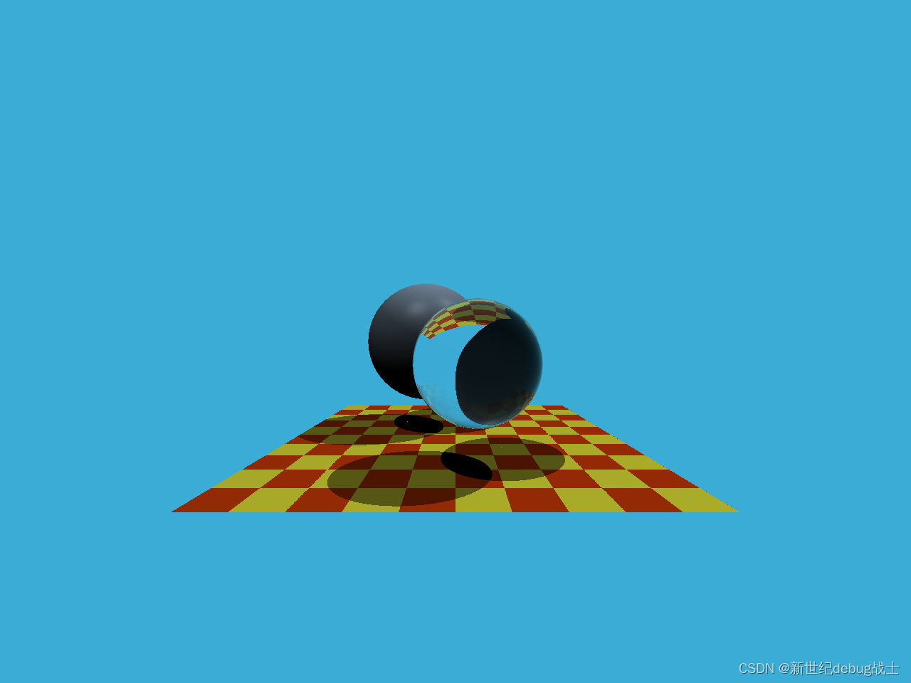
}最终渲染的效果如图:


 被折叠的 条评论
为什么被折叠?
被折叠的 条评论
为什么被折叠?
 到【灌水乐园】发言


