


 本文介绍如何利用Grub引导PE格式的操作系统内核,包括设置多启动规范头的具体步骤,以及如何针对Windows背景下的开发者进行代码适配。
http://ksrenevasan.blogspot.com/2005/10/writing-multiboot-pe-kernels-using.html
Aspiring operating system developers who target x86 often don’t get beyondwriting a boot sector (seldom do they even complete it) because of theinordinate amount of time needed to understand the “tricks” required to get theprocessor into a “sane” mode of operation before the kernel can start executing.That’s why newbie kernel developers are always advised to use an alternativelike Grub to bootstrap theirkernel so that they can concentrate on implementing the kernel itself ratherthan the plumbing. Why Grub? Because it is one of the bootloaders thatimplements the “Multiboot”specification (correctly?).
This specification details the steps thatOS / bootloader developers need to follow in order to be compatible with (andusable by) each other. In very simple terms, multiboot compliant operatingsystems need to have a 48 byte structure called the Multiboot header (in itsentirety), somewhere within the first 8192 bytes of the kernel image, longwordaligned.
Everyother “roll your own OS” tutorial invariably talks about how you can make yourkernel bootable by Grub. But all of these assume that you are using the GCCtoolset. If you are from a windows background you are out of luck. The GCCtoolset itself is not very difficult to learn, but I’m sure you’d feel more athome using the tools you’re familiar with for a long time. At least I do andthat’s why I set out writing this post about how you can make grub boot yourVC++ kernel.
Making a boot loader like Grub boot a custom kernel is easy(at least compared to the effort it takes to create a new boot loader). Thekernel itself is only a binary in some file format (AOUT, ELF, PE etc.). Forexample the Windows kernel (%WINDRIVE%\Windows\System32\NTOSKRNL.EXE) uses thePE file format (Try dumpbin /ALL %WINDRIVE%\Windows\System32\NTOSKRNL.EXE) thatis also used by user mode programs under windows. Similarly, the Linux kernelprobably gets compiled into the ELF file format. Now, expecting a bootloader to“know” all executable file formats is probably not a good idea. The multibootspecification takes a different approach to load a kernel image onto RAM. Ituses fields in the multiboot header to denote the parts of the kernel image thatneeds to be loaded. Grub “knows” how to load an ELF binary, not a PE. So we aregoing to give it “hints” in our multiboot header that will help it load thekernel image properly. Time for some code…
/* kernel.h */
#ifndef__kernel_h__
#define__kernel_h__
#definedd(x) \
__asm _emit (x) & 0xff \
__asm _emit (x)>> 8 & 0xff \
__asm _emit (x)>> 16 & 0xff \
__asm _emit (x)>> 24 & 0xff
#defineKERNEL_STACK 0x00103fff
#defineKERNEL_START 0x00101000
#defineKERNEL_LENGTH 0x0000200F
void main(unsigned long,unsigned long);
#endif
/* kernel.c */
#include"kernel.h"
__declspec(naked) void__multiboot_entry__(void)
{
__asm{
multiboot_header:
dd(0x1BADB002) ;magic
dd(1<< 16) ; flags
dd(-(0x1BADB002+ (1 << 16))) ; checksum
dd(0x00101000) ;header_addr
dd(0x00101000) ;load_addr
dd(0x0010200F) ;load_end_addr
dd(0x0010200F) ;bss_end_addr
dd(0x00101030) ;entry_addr
dd(0x00000000) ;mode_type
dd(0x00000000) ;width
dd(0x00000000) ;height
dd(0x00000000) ;depth
kernel_entry:
mov esp, KERNEL_STACK
xor ecx, ecx
push ecx
popf
push eax
push ebx
call main
jmp $
}
}
void main(unsigned long magic,unsigned long addr)
{
char *string = "HelloWorld!", *ch;
unsigned short*vidmem = (unsigned short *) 0xB8000;
inti;
for(ch = string, i =0; *ch; ch++, i++)
vidmem[i] =(unsigned char) *ch | 0x0700;
}
The first fieldin the header is a magic number that the bootloader will use to locate the startof the multiboot header in the image. The second field denotes the features thatthe OS expects from the boot loader. To keep the code simple, I’ve ignored bits0-15 (about which you can read in the multiboot specification). I’ve set bit 16of this field. This means that the fields at offsets 8-24 in the Multibootheader are valid, and the boot loader should use them instead of the fields inthe actual executable header to calculate where to load the OS image. Thismechanism enables the bootloader load kernel images whose format is notunderstood “natively”.
Before examining what the fields at offsets 8-24mean, let’s take a look at the PE file format.
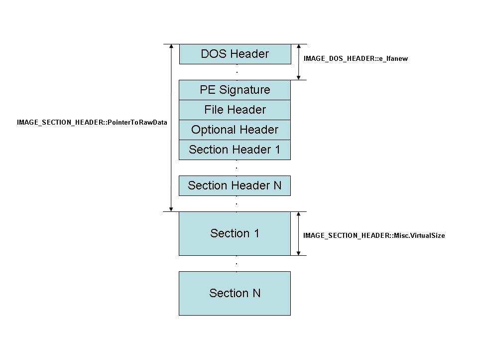
A PE image starts with a couple of standard headers (DOS / PE/ File / Optional). Following these is a set of headers called the sectionheaders that contain information about the different sections in the image. (Fora more verbose explanation of the PE file format read MattPietrek’s article) A section typically contains either code or data. Theabove kernel if compiled with the following switches
cl /Gd
/Fokernel.obj
/Fm
/TC
/c
kernel.c
link /safeseh:no
/filealign:0x1000
/BASE:0x100000
/MAP: kernel.map
/ENTRY:__multiboot_entry__kernel.obj
/NODEFAULTLIB:LIBC
/SUBSYSTEM:CONSOLE
/OUT:kernel.exe
Produces a .EXE with two sections named .text and .data.Sections are aligned on a 4K boundary using the undocumented linker switch/filealign:0x1000.
Armed with this information about the PE file format,lets examine the fields at offset 8-24 in the multiboot header.
dd(0x1BADB002) ;magic
dd(1<< 16) ; flags
dd(-(0x1BADB002 + (1 <<16))) ; checksum
dd(0x00101000) ;header_addr
dd(0x00101000) ;load_addr
dd(0x0010200F) ;load_end_addr
dd(0x0010200F) ;bss_end_addr
dd(0x00101030) ;entry_addr
dd(0x00000000) ;mode_type
dd(0x00000000) ;width
dd(0x00000000) ;height
dd(0x00000000) ;depth
The field at offset 8, Checksum, needs to be set to – (magic+ flags). Grub loads the .text section of the kernel into physical address0x100000 (1 MB) + Offset by default. The offset is specified indirectly usingthe header_addr and load_addr fields. According to the specification header_addr“Contains the address corresponding to the beginning of the Multiboot header”.IMHO, this is a bit confusing. What it really means is, if the image file isloaded at 0x100000, the physical address of the starting of the multiboot headeris header_addr. The next field load_addr contains the physical address of thebeginning of the .text section. (In our case both are the same because themultiboot header is the first 48 bytes of the .text section). The next fieldload_end_addr is used to determine how many bytes of the image file actuallyneeds to be loaded. (Note that the .text and .data sections need to besuccessive in the image for this to work). In our case 0x102000 is where datasection starts and it has a size of 0xF bytes and hence the value 0x10200F forload_end_addr. Grub, now knows it needs to load 0x10200F – 0x101000 bytes. Thenext field according to the multiboot specification, needs to be set to 0 if abss section doesn’t exist. (As in our case). However Grub refuses to load theimage if bss_end_addr is set to 0, so I set it to 0x10200F (same as theprevious). The rest of the code is perhaps obvious and hence doesn’t deserve anexplanation.
Our multiboot compliant PE kernel is now ready :)


 58
58

 被折叠的 条评论
为什么被折叠?
被折叠的 条评论
为什么被折叠?
 到【灌水乐园】发言


