


1,前言。
相机的成像过程实质上是坐标系的转换。首先空间中的点由“世界坐标系”转换到“相机坐标系”,然后再将其投影到成像平面(图像物理坐标系),最后再将成像的平面上的数据转换为图像像素坐标系。但是由于透镜的制造精度以及组装工艺的偏差会出现不同的畸变,导致图像失真。
镜头畸变分为径向畸变和切向畸变。径向畸变是由镜头形状缺陷造成,它又分为枕形畸变和桶形畸变。
对于一般低精度的场合,只考虑径向畸变即可,因为切向畸变的影响远小于径向畸变。因此如果要进行图像畸变矫正就需要通过标定获取相机的参数。同时为了将图像的坐标系中的像素坐标系与世界坐标系中的坐标距离对应起来,就需要了解相机的外部参数信息,换算其在世界坐标系中的实际距离。相机标定就是获取相机内部参数和外部参数的过程。
2,相机标定的方法。
传统标定法:标定精度较高,但在非线性相机模型下计算十分复杂,标定速度较低,通常用于精度要求较高的线性系统。
自标定法:不需要借助参考物,操作简单且计算速度较快,但其标度精度及鲁棒性较低,只适用于速度要求较高精度较低的系统。
张正友标定:介于前面两种标定法之间,具有操作简单,标定精度高,鲁棒性好的优点,较为广泛使用。
3,内部参数和外部参数。
内部参数:相机的焦距、畸变系数、像素间距、中心点坐标、图像的宽和高等。这些参数虽然可以从制造商提供的说明书中查询,单其精度性不一定满足要求,因此只能作为参考,在实际中还需要对其进行标定,通过标定可以对这些参数进行修正。不同的相机,其内部参数也不相同,这取决于相机和镜头的类型,以及选择的畸变类型。
外部参数:相机的外部参数描述相机坐标系与世界坐标系的关系,即相机在世界坐标系中的三位位置,如相机的X轴坐标,Y轴坐标,Z轴坐标,以及相机的朝向。
4,相机的畸变。
径向畸变:矢量端点沿长度方向的变化,即矢量长度的变化。
切向畸变:矢量端点沿切线方向发生的变化,即矢量角度的变化。
5,Halcon标定。
1,准备标定板。
用halcon代码生成用于打印标定板的描述文件及标定板图像的ps文件。
*生成标定板文件
 gen_caltab (7, 7, 0.0125, 0.5, 'caltab.descr', 'caltab.ps')

生成的.descr与caltab.ps文件。

备注:
caltab.descr:对标记点的半径,坐标,行,列进行描述的文件。
有.cpd与.descr两种扩展 名的标定板描述文件:
.cpd描述文件:使用create_caltab函数生成,这种格式适用于六边形排列的标定板,通常在深色背景上有浅色的标记。
.descr文件:使用gen_caltab函数生成,用于矩形排列的标定板,通常用于浅色背景下深色标记。
Halcon已提供的.cpd与.descr文件位于:D:\Program Files\MVTec\HALCON-12.0\calib目录下。
caltab.descr文件详情如下:
# Plate Description Version 2
# HALCON Version 12.0 --  Sun Dec 29 11:09:19 2024
# Description of the standard calibration plate
# used for the camera calibration in HALCON
# (generated by gen_caltab)
#
#

# 7 rows x 7 columns
# Width, height of calibration plate [meter]: 0.1, 0.1
# Distance between mark centers [meter]: 0.0125

# Number of marks in y-dimension (rows)
r 7

# Number of marks in x-dimension (columns)
c 7

#   offset of coordinate system in z-dimension [meter] (optional):
z 0

# Rectangular border (rim and black frame) of calibration plate
#   rim of the calibration plate (min x, max y, max x, min y) [meter]:
o -0.05125 0.05125 0.05125 -0.05125
#   outer border of the black frame (min x, max y, max x, min y) [meter]:
i -0.05 0.05 0.05 -0.05
#   triangular corner mark given by two corner points (x,y, x,y) [meter]
#   (optional):
t -0.05 -0.0375 -0.0375 -0.05

#   width of the black frame [meter]:
w 0.003125

# calibration marks:  x y radius [meter]

# calibration marks at y = -0.0375 m
-0.0375 -0.0375 0.003125
-0.025 -0.0375 0.003125
-0.0125 -0.0375 0.003125
0 -0.0375 0.003125
0.0125 -0.0375 0.003125
0.025 -0.0375 0.003125
0.0375 -0.0375 0.003125

# calibration marks at y = -0.025 m
-0.0375 -0.025 0.003125
-0.025 -0.025 0.003125
-0.0125 -0.025 0.003125
0 -0.025 0.003125
0.0125 -0.025 0.003125
0.025 -0.025 0.003125
0.0375 -0.025 0.003125

# calibration marks at y = -0.0125 m
-0.0375 -0.0125 0.003125
-0.025 -0.0125 0.003125
-0.0125 -0.0125 0.003125
0 -0.0125 0.003125
0.0125 -0.0125 0.003125
0.025 -0.0125 0.003125
0.0375 -0.0125 0.003125

# calibration marks at y = 0 m
-0.0375 0 0.003125
-0.025 0 0.003125
-0.0125 0 0.003125
0 0 0.003125
0.0125 0 0.003125
0.025 0 0.003125
0.0375 0 0.003125

# calibration marks at y = 0.0125 m
-0.0375 0.0125 0.003125
-0.025 0.0125 0.003125
-0.0125 0.0125 0.003125
0 0.0125 0.003125
0.0125 0.0125 0.003125
0.025 0.0125 0.003125
0.0375 0.0125 0.003125

# calibration marks at y = 0.025 m
-0.0375 0.025 0.003125
-0.025 0.025 0.003125
-0.0125 0.025 0.003125
0 0.025 0.003125
0.0125 0.025 0.003125
0.025 0.025 0.003125
0.0375 0.025 0.003125

# calibration marks at y = 0.0375 m
-0.0375 0.0375 0.003125
-0.025 0.0375 0.003125
-0.0125 0.0375 0.003125
0 0.0375 0.003125
0.0125 0.0375 0.003125
0.025 0.0375 0.003125
0.0375 0.0375 0.003125
caltab.ps:可直接用于打印的标定板图像文件。
打印出的标定板如下:

2,内部参数与外部参数获取
1,使用Halcon算子获取
相机内部参数标定算子所在位置:

算子如下:
*生成标定板文件
 *gen_caltab (7, 7, 0.0125, 0.5, 'caltab.descr', 'caltab.ps')
ImgPath := '3d_machine_vision/calib/'
dev_close_window ()
dev_open_window (0, 0, 652, 494, 'black', WindowHandle)
dev_update_off ()
dev_set_draw ('margin')
dev_set_line_width (3)
OpSystem := environment('OS')
set_display_font (WindowHandle, 14, 'mono', 'true', 'false')
*
* Calibrate the camera.
* StartCamPar := [Focus,Kappa,Sx,Sy,Cx,Cy,ImageWidth,ImageHeight]
*Focus:相机的焦距,如果是远心相机,则焦距为0
*Kappa:畸变系数,初始值可以设置为0
*Sx、Sy:单个像元的宽,高(可从相机说明书中获取)
*Cx、Cy:图像的原点坐标,初始值可认为是图像的中心点,即坐标分为为图像的宽度和高度的一半
*ImageWidth,ImageHeight:采集图像的宽和高
StartCamPar := [0.016,0,0.0000074,0.0000074,326,247,652,494]
create_calib_data ('calibration_object', 1, 1, CalibDataID)
*设置为面阵模式
set_calib_data_cam_param (CalibDataID, 0, 'area_scan_division', StartCamPar)
*设置标定描述文件
set_calib_data_calib_object (CalibDataID, 0, 'caltab.descr')
NumImages := 10
* Note, we do not use the image from which the pose of the measurement plane can be derived
for I := 1 to NumImages by 1
    read_image (Image, ImgPath + 'calib_' + I$'02d')
    dev_display (Image)
    find_calib_object (Image, CalibDataID, 0, 0, I, [], [])
    get_calib_data_observ_contours (Caltab, CalibDataID, 'caltab', 0, 0, I)
    dev_set_color ('green')
    dev_display (Caltab)
endfor
*标定相机内参
calibrate_cameras (CalibDataID, Error)
*获取标定后的相机内部参数
get_calib_data (CalibDataID, 'camera', 0, 'params', CamParam)
* 将相机内部参数写入到文件
write_cam_par (CamParam, 'camera_parameters.dat')
Message := 'Interior camera parameters have'
Message[1] := 'been written to file'
disp_message (WindowHandle, Message, 'window', 12, 12, 'red', 'false')
clear_calib_data (CalibDataID)
相机外部参数标定算子所在位置:

算子如下:
* Attention:
* This program reads the internal camera parameters from the file
* 'camera_parameters.dat', which, e.g., could be generated by the program
* 'camera_calibration_internal.hdev'
*
ImgPath := '3d_machine_vision/calib/'
dev_close_window ()
dev_open_window (0, 0, 652, 494, 'black', WindowHandle)
dev_update_off ()
dev_set_draw ('margin')
dev_set_line_width (1)
set_display_font (WindowHandle, 14, 'mono', 'true', 'false')
* 从文件中读取内部参数
try
    read_cam_par ('camera_parameters.dat', CamParam)
catch (Exception)
    * run 'camera_calibration_internal.hdev' first to generate camera
    * parameter file 'camera_parameters.dat'
    stop ()
endtry
*
* Determine the external camera parameters and world coodinates from image points
*
* The external camera parameters can be determined from an image, where the
* calibration plate is positioned directly on the measurement plane
read_image (Image, ImgPath + 'calib_11')
dev_display (Image)
*标定描述文件
CaltabName := 'caltab.descr'
create_calib_data ('calibration_object', 1, 1, CalibDataID)
* Here, the final camera parameters are already known and can be used instead
* of the starting values used in the program 'camera_calibration_internal.hdev'
set_calib_data_cam_param (CalibDataID, 0, 'area_scan_division', CamParam)
set_calib_data_calib_object (CalibDataID, 0, CaltabName)
find_calib_object (Image, CalibDataID, 0, 0, 1, [], [])
get_calib_data_observ_contours (Caltab, CalibDataID, 'caltab', 0, 0, 1)
*获取粗略估计的姿态(外部参数)
get_calib_data_observ_points (CalibDataID, 0, 0, 1, RCoord, CCoord, Index, PoseForCalibrationPlate)
dev_set_color ('green')
dev_display (Caltab)
dev_set_color ('red')
disp_caltab (WindowHandle, CaltabName, CamParam, PoseForCalibrationPlate, 1)
dev_set_line_width (3)
disp_circle (WindowHandle, RCoord, CCoord, gen_tuple_const(|RCoord|,1.5))
* caltab_points (CaltabName, X, Y, Z)
* calibrate_cameras (CalibDataID, Error)
* To take the thickness of the calibration plate into account, the z-value
* of the origin given by the camera pose has to be translated by the
* thickness of the calibration plate.
* Deactivate the following line if you do not want to add the correction.
*设置标定板的厚度,如果没有则省略
set_origin_pose (PoseForCalibrationPlate, 0, 0, 0.00075, PoseForCalibrationPlate)
disp_continue_message (WindowHandle, 'black', 'true')
stop ()
* Alternatively, the external camera parameters can  be determined from
* at least three point correspondances between the WCS and the pixel coordinate system
read_image (Image, ImgPath + 'caliper_01')
dev_display (Image)
* Set the world coordinates of three points on the rule
*在尺上选择点设置世界坐标
X := [0,50,100,80]
Y := [5,0,5,0]
Z := [0,0,0,0]
* Set the respective image plane coordinates of the three points
*设置选择点在图像上对应的像素坐标
RCoord := [414,227,85,128]
CCoord := [119,318,550,448]
*
disp_cross (WindowHandle, RCoord, CCoord, 6, 0)
* create_pose (-50, 25, 400, 0, 0, -30, 'Rp+T', 'gba', 'point', InitialPose)
*生成外部参数(姿态参数)
vector_to_pose (X, Y, Z, RCoord, CCoord, CamParam, 'iterative', 'error', FinalPose, Errors)
*将外部参数写入到文件
write_pose (FinalPose, 'pose_from_three_points.dat')

* Now, transform a point measured interactively into the WCS
dev_update_window ('on')
dev_display (Image)
while (1)
    disp_message (WindowHandle, 'Measure one point: left mouse button', 'window', 12, 12, 'red', 'false')
    disp_message (WindowHandle, 'Exit measure mode: right mouse button', 'window', 36, 12, 'red', 'false')
    get_mbutton (WindowHandle, Row, Column, Button)
    if (Button == 4)
        break
    endif
    dev_display (Image)
    dev_set_color ('green')
    disp_cross (WindowHandle, Row, Column, 6, 0)
    image_points_to_world_plane (CamParam, FinalPose, Row, Column, 1, X1, Y1)

    disp_message (WindowHandle, 'X = ' + X1, 'window', 320, 400, 'red', 'false')
    disp_message (WindowHandle, 'Y = ' + Y1, 'window', 340, 400, 'red', 'false')
endwhile
2,使用助手获取相机内部参数与外部参数。
选择标定助手

设置参数

选择拍摄的各个角度标定板图像

不同角度的标定板图像

查看标定结果

6,单相机标定应用。
* gen_caltab (7, 7, 0.0125, 0.5, 'caltab.descr', 'caltab.ps')
dev_close_window ()
read_image (Image, '3d_machine_vision/calib/calib_10')
get_image_size(Image, Width, Height)
dev_open_window (0, 0, Width, Height, 'black', WindowHandle)
dev_display (Image)
*测量两个点之间的世界距离
*因为标定板相邻的两个圆远心之间的距离是12.5mm,所以用这个进行测试
*读取相机内参
read_cam_par ('camera_parameters.dat', CameraParam)
*读取相机的外参
read_pose ('pose_from_three_points.dat', Pose)
*获取两个相邻圆的圆形图像距离
threshold (Image, Region, 0, 100)
connection (Region, ConnectedRegions)
select_shape (ConnectedRegions, SelectedRegions, ['area','row','column'], 'and', [0,305.96,360.09], [131651,345.41,500])
*获取该两点的相机坐标
gen_contour_region_xld (SelectedRegions, Contours, 'border')
dev_set_color ('green')
dev_set_line_width (2)

dev_display (Image)
dev_display (Contours)
*获取两个选定区域的坐标
area_center (SelectedRegions, Area, Row, Column)

*映射成世界坐标
image_points_to_world_plane (CameraParam, Pose, Row, Column, 'mm', X, Y)
*计算两点之间的距离
distance_pp (X[1], Y[1], X[0], Y[0], Distance)
dev_set_color ('red')
disp_line (WindowHandle, Row[0], Column[0], Row[1], Column[1])
disp_message (WindowHandle,'Distance:'+ Distance$'.2f'+'mm', 'window', 20, 20, 'green', 'false') 
7,与机器手联动的手眼标定。
手眼标定存在两种模式,但是目的是一致:均是获取标定对象在相机坐标系中的姿态:CalObjInCamPose,以下对两种模式进行介绍。
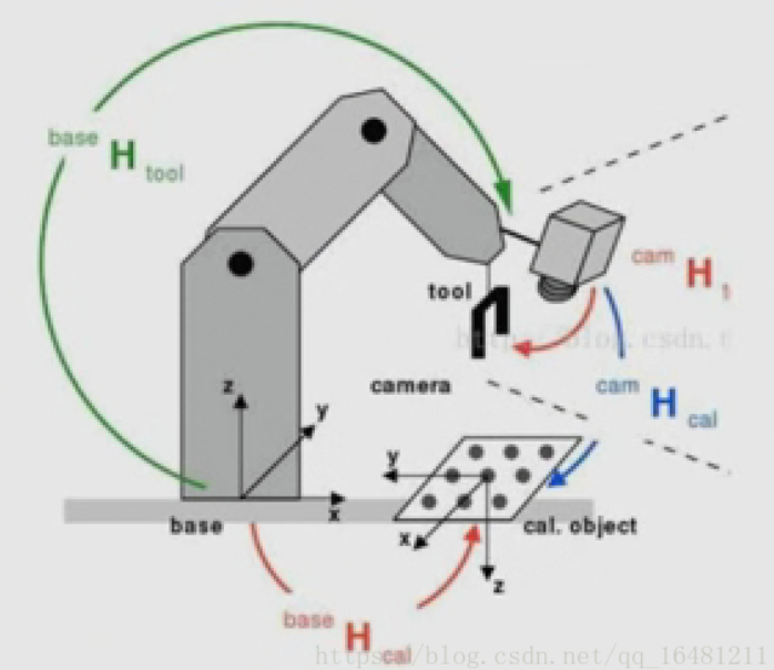
1,eye to hand:眼到手模式。
静止的相机对固定在机器手臂上,随机器手臂移动的标定板进行拍照。
*参考示例库:handeye_stationarycam_calibration.hdev
*场景:
*这个例子展示eyetohand:眼到手模式的标定。
*场景描述:
*相机静止不动,拍摄固定在机械臂上,随着机械臂进行移动的标定板。
*目的:
*获取标定对象在相机坐标系中的姿态:CalObjInCamPose
*在这种情况下,需要确定两个未知的姿势:
* -BaseInCamPose:机器人基座在相机坐标系中的姿态。
* -CalObjInToolPose:标定对象在工具坐标系中的位姿
dev_update_off ()
* Directories with calibration images and data files
ImageNameStart := '3d_machine_vision/handeye/stationarycam_calib3cm_'
DataNameStart := 'handeye/stationarycam_'
NumImages := 17
* Read image
read_image (Image, ImageNameStart + '00')
get_image_size (Image, Width, Height)
* Open window
dev_close_window ()
dev_open_window (0, 0, Width, Height, 'black', WindowHandle)
dev_set_line_width (2)
dev_set_draw ('margin')
dev_display (Image)
* Set font
set_display_font (WindowHandle, 14, 'mono', 'true', 'false')
* Load the calibration plate description file.
* Make sure that the file is in the current directory,
* the HALCONROOT/calib directory, or use an absolut path
CalTabFile := 'caltab.descr'
*----------------------1,从相机内参文件中读取相机内部参数
read_cam_par ('camera_param.cal', StartCamParam)
* Create the calibration model for the hand eye calibration
create_calib_data ('hand_eye_stationary_cam', 1, 1, CalibDataID)
set_calib_data_cam_param (CalibDataID, 0, 'area_scan_division', StartCamParam)
*----------------------2,从标定板描述文件中读取标定板描述
set_calib_data_calib_object (CalibDataID, 0, CalTabFile)
set_calib_data (CalibDataID, 'model', 'general', 'optimization_method', 'nonlinear')
disp_message (WindowHandle, 'The calibration data model was created', 'window', 12, 12, 'black', 'true')
disp_continue_message (WindowHandle, 'black', 'true')
stop ()
* Start the loop over the calibration images
for I := 0 to NumImages - 1 by 1
read_image (Image, ImageNameStart + I$'02d')
* Search for the calibration plate, extract the marks and the
* pose of it, and store the results in the calibration data model of the
* hand-eye calibration
find_calib_object (Image, CalibDataID, 0, 0, I, [], [])
get_calib_data_observ_contours (Caltab, CalibDataID, 'caltab', 0, 0, I)
get_calib_data_observ_points (CalibDataID, 0, 0, I, RCoord, CCoord, Index, CalObjInCamPose)
* Visualize the extracted calibration marks and the estimated pose (coordinate system)
dev_set_color ('green')
dev_display (Image)
dev_display (Caltab)
dev_set_color ('yellow')
disp_cross (WindowHandle, RCoord, CCoord, 6, 0)
dev_set_colored (3)
disp_3d_coord_system (WindowHandle, StartCamParam, CalObjInCamPose, 0.01)
*----------------------3,从文件中读取ToolInBasePose(工件在机器手基础坐标系中的姿态)
* Read pose of tool in robot base coordinates (ToolInBasePose)
read_pose ('robot_pose_' + I$'02d' + '.dat', ToolInBasePose)
* Set the pose tool in robot base coordinates in the calibration data model
set_calib_data (CalibDataID, 'tool', I, 'tool_in_base_pose', ToolInBasePose)
* Uncomment to inspect visualization
* disp_message (WindowHandle, 'Extracting data from calibration image ' + (I + 1) + ' of ' + NumImages, 'window', -1, -1, 'black', 'true')
* disp_continue_message (WindowHandle, 'black', 'true')
* stop ()
endfor
disp_message (WindowHandle, 'All relevant data has been set in the calibration data model', 'window', 12, 12, 'black', 'true')
disp_continue_message (WindowHandle, 'black', 'true')
stop ()
* Perform hand-eye calibration
* Internally before performing the hand-eye calibration the cameras are calibrated
* and the calibrated poses of the calibration object in the camera are used.
dev_display (Image)
disp_message (WindowHandle, 'Performing the hand-eye calibration', 'window', 12, 12, 'black', 'true')
*---------------------------4,进行手眼标定
calibrate_hand_eye (CalibDataID, Errors)
* 查询标定后的相机内参
get_calib_data (CalibDataID, 'camera', 0, 'params', CamParam)
* 查询机器手基础在相机坐标系的姿态:BaseInCamPose
get_calib_data (CalibDataID, 'camera', 0, 'base_in_cam_pose', BaseInCamPose)
* 查询标定板在工件坐标系的姿态:ObjInToolPose
get_calib_data (CalibDataID, 'calib_obj', 0, 'obj_in_tool_pose', ObjInToolPose)
*是否启用异常弹窗
dev_get_preferences ('suppress_handled_exceptions_dlg', PreferenceValue)
dev_set_preferences ('suppress_handled_exceptions_dlg', 'true')
try
*---------------------5,保存标定后的相机内参
* Store the camera parameters to file
write_cam_par (CamParam, 'final_campar.dat')
*---------------------6,保存BaseInCamPose,ObjInToolPose参数
* Save the hand eye calibration results to file
write_pose (BaseInCamPose, 'final_pose_cam_base.dat')
write_pose (ObjInToolPose, 'final_pose_tool_calplate.dat')
catch (Exception)
* Do nothing
endtry
dev_set_preferences ('suppress_handled_exceptions_dlg', PreferenceValue)
* Display calibration errors of the hand-eye calibration
Message := 'Quality of the results: root mean square maximum'
Message[1] := 'Translation part in meter: ' + Errors[0]$'6.4f' + ' ' + Errors[2]$'6.4f'
Message[2] := 'Rotation part in degree: ' + Errors[1]$'6.4f' + ' ' + Errors[3]$'6.4f'
disp_message (WindowHandle, Message, 'window', 12, 12, 'black', 'true')
disp_continue_message (WindowHandle, 'black', 'true')
stop ()
* For the given camera, get the corresponding pose indices and calibration object indices
query_calib_data_observ_indices (CalibDataID, 'camera', 0, CalibObjIdx, PoseIds)
* Compute the pose of the calibration object in the camera coordinate
* system via calibrated poses and the ToolInBasePose and visualize it.
for I := 0 to NumImages - 1 by 1
read_image (Image, ImageNameStart + I$'02d')
* Obtain the pose of the tool in robot base coordinates used in the calibration.
* The index corresponds to the index of the pose of the observation object.
get_calib_data (CalibDataID, 'tool', PoseIds[I], 'tool_in_base_pose', ToolInBasePose)
dev_display (Image)
* Compute the pose of the calibration plate with respect to the camera
* ------------------------7,最终目的:计算标定对象在相机坐标系的姿态:CalObjInCamPose
calc_calplate_pose_stationarycam (ObjInToolPose, BaseInCamPose, ToolInBasePose, CalObjInCamPose)
dev_set_colored (3)
disp_3d_coord_system (WindowHandle, CamParam, CalObjInCamPose, 0.01)
Message := 'Using the calibration results to display the'
Message[1] := 'coordinate system in image ' + (I + 1) + ' of ' + NumImages
disp_message (WindowHandle, Message, 'window', 12, 12, 'black', 'true')
if (I < NumImages - 1)
disp_continue_message (WindowHandle, 'black', 'true')
stop ()
endif
endfor
* Clear the data model
clear_calib_data (CalibDataID)
*
* After the hand-eye calibration the computed pose
* BaseInCamPose can be used in robotic grasping applications.
* If the tool coordinate system is placed at the gripper
* and a object detected at ObjInCamPose shall be grasped,
* the pose of the detected object relative
* to the robot base coordinate system has to be computed.
pose_invert (BaseInCamPose, CamInBasePose)
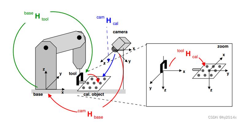
pose_compose (CamInBasePose, CalObjInCamPose, ObjInBasePose)2,eye in hand:眼在手上模式。
标定板不动,机器手带着相机在各个角度对静止不动的标定板进行拍照。
* 参考示例库:handeye_movingcam_calibration.hdev

*场景:
*这个例子展示手眼标定-眼在手上模式(eye in hand)。
*场景描述:
* 标定板不动,机器手带着相机在各个角度对静止不动的标定板进行拍照。
*目的:
*获取标定对象在相机坐标系中的姿态:CalObjInCamPose


*由三个姿态组成
  *A:ToolInCamPose:工件在相机坐标系中的姿态
  *B: BaseInToolPose:机器手基础在工件坐标系中的姿态(由机器手计算提供)
  *C: CalibObjInBasePose:标定对象在机器手基础坐标系中的姿态
*在这种情况下,手眼校准的目标是确定两个未知的姿势:
  * 1,obj在机器人基础坐标系中的位姿(CalObjInBasePose)。
  * 2,tool在相机坐标系中的姿态(ToolInCamPose)。
*理论上,作为输入,该方法至少需要3个标定点。然而,建议使用至少10个姿势。
* create_pose (0.412834, -0.001809, 0.052459, 0.251, 90, 0, 'Rp+T', 'abg', 'point', Pose)
* for i := 0 to 13 by 1
*     write_pose (Pose, 'robot_pose_' + i$'02d' + '.dat')
* endfor
dev_update_off ()
* 读取用于标定图像文件
ImageNameStart := '3d_machine_vision/handeye/movingcam_calib3cm_'
DataNameStart := 'handeye/movingcam_'
NumImages := 14
read_image (Image, ImageNameStart + '00')
dev_close_window ()
get_image_size (Image, Width, Height)
dev_open_window (0, 0, Width, Height, 'black', WindowHandle)
dev_set_line_width (2)
dev_set_draw ('margin')
dev_display (Image)
set_display_font (WindowHandle, 14, 'mono', 'true', 'false')
* Load the calibration plate description file.
* Make sure that the file is in the current directory or
* in HALCONROOT/calib, or use an absolute path.
CalTabFile := 'caltab.descr'

*----------------1,读取相机的内参数据文件
read_cam_par ('camera_param.cal', StartCamParam)
* 创建手眼标定模型
* 用相机观察校准对象的位置
create_calib_data ('hand_eye_moving_cam', 1, 1, CalibDataID)
* Set the camera type used
set_calib_data_cam_param (CalibDataID, 0, 'area_scan_division', StartCamParam)

*----------------2,设置标定板的描述文件
set_calib_data_calib_object (CalibDataID, 0, CalTabFile)
* Start the loop over the calibration images
* 设置优化方法
set_calib_data (CalibDataID, 'model', 'general', 'optimization_method', 'nonlinear')
disp_message (WindowHandle, 'The calibration data model was created', 'window', 12, 12, 'black', 'true')
disp_continue_message (WindowHandle, 'black', 'true')
stop ()
for I := 0 to NumImages - 1 by 1
    read_image (Image, ImageNameStart + I$'02d')
    * Search for the calibration plate, extract the marks and the
    * pose of it, and store the results in the calibration data
    * The poses are stored in the calibration data model for use by
    * the hand eye calibration and do not have to be set explicitly
    find_calib_object (Image, CalibDataID, 0, 0, I, [], [])
    get_calib_data_observ_contours (Caltab, CalibDataID, 'caltab', 0, 0, I)
    get_calib_data_observ_points (CalibDataID, 0, 0, I, RCoord, CCoord, Index, PoseForCalibrationPlate)
    * Visualize the extracted calibration marks and the estimated pose (coordinate system)
    dev_set_color ('green')
    dev_display (Image)
    dev_display (Caltab)
    dev_set_color ('yellow')
    disp_cross (WindowHandle, RCoord, CCoord, 6, 0)
    dev_set_colored (3)
    disp_3d_coord_system (WindowHandle, StartCamParam, PoseForCalibrationPlate, 0.01)

    *---------------3, 读取tool在robot基础坐标系的pose (ToolInBasePose)
    *数据位三个位移+三个旋转+类型
    read_pose ( 'robot_pose_' + I$'02d' + '.dat', ToolInBasePose)
    * Set the pose tool in robot base coordinates in the calibration data model
    set_calib_data (CalibDataID, 'tool', I, 'tool_in_base_pose', ToolInBasePose)
    * Uncomment for inspection of visualization
*     disp_message (WindowHandle, 'Extracting data from calibration image ' + (I + 1) + ' of ' + NumImages, 'window', 12, 12, 'black', 'true')
*     disp_continue_message (WindowHandle, 'black', 'true')
*     stop ()
endfor
disp_message (WindowHandle, 'All relevant data has been set in the calibration data model', 'window', 12, 12, 'black', 'true')
disp_continue_message (WindowHandle, 'black', 'true')
stop ()
*执行手眼校准并将结果存储到文件中
*相机的校准是事先在内部完成的

*-------------------4,执行手眼标定
dev_display (Image)
disp_message (WindowHandle, 'Performing the hand-eye calibration', 'window', 12, 12, 'black', 'true')
calibrate_hand_eye (CalibDataID, Errors)

* ------------------5,查询标定后的相机内部参数
get_calib_data (CalibDataID, 'camera', 0, 'params', CamParam)
* Get poses computed by the hand eye calibration

*-------------------6,查询ToolInCamPose:tool在相机上的姿态,obj_in_base_pose:obj在基础坐标系上的姿态
get_calib_data (CalibDataID, 'camera', 0, 'tool_in_cam_pose', ToolInCamPose)
get_calib_data (CalibDataID, 'calib_obj', 0, 'obj_in_base_pose', CalObjInBasePose)
*异常时是否弹出对话框
dev_get_preferences ('suppress_handled_exceptions_dlg', PreferenceValue)
dev_set_preferences ('suppress_handled_exceptions_dlg', 'true')
try
    * Handle situation where user does not have the permission
    * to write in the current directory.
    *
    *---------------7, 保存相机内参
    write_cam_par (CamParam,  'final_campar.dat')
    * Save the hand eye calibration results to file

    *---------------8,保存ToolInCamPose:tool在相机的姿态
    write_pose (ToolInCamPose,'final_pose_cam_tool.dat')

    *---------------9,保存ObjInBasePose:obj在机器手基础坐标系上的姿态
    write_pose (CalObjInBasePose, DataNameStart + 'final_pose_base_calplate.dat')
catch (Exception)
    * do nothing
endtry
dev_set_preferences ('suppress_handled_exceptions_dlg', PreferenceValue)
dev_display (Image)
* Display calibration errors
*显示标定错误
Message := 'Quality of the results:      root mean square    maximum'
Message[1] := 'Translation part in meter:      ' + Errors[0]$'6.4f' + '           ' + Errors[2]$'6.4f'
Message[2] := 'Rotation part in degree:        ' + Errors[1]$'6.4f' + '           ' + Errors[3]$'6.4f'
disp_message (WindowHandle, Message, 'window', 12, 12, 'black', 'true')
disp_continue_message (WindowHandle, 'black', 'true')
stop ()
* 查询摄像机、校准对象、校准对象位姿之间的关系信息。
query_calib_data_observ_indices (CalibDataID, 'camera', 0, CalibObjIdx, PoseIds)
* Compute the pose of the calibration object in the camera coordinate
* system via calibrated poses and the ToolInBasePose and visualize it.
for I := 0 to NumImages - 1 by 1
    read_image (Image, ImageNameStart + I$'02d')
    dev_display (Image)
    * Obtain the pose of the tool in robot base coordinates used in the calibration.
    * The index corresponds to the index of the pose of the observation object.
    get_calib_data (CalibDataID, 'tool', PoseIds[I], 'tool_in_base_pose', ToolInBasePose)

    * --------------10,计算校准对象相对于相机的姿态
    calc_calplate_pose_movingcam (CalObjInBasePose, ToolInCamPose, ToolInBasePose, CalObjInCamPose)
    * Display the coordinate system
    dev_set_colored (3)
    disp_3d_coord_system (WindowHandle, CamParam, CalObjInCamPose, 0.01)
    Message := 'Using the calibration results to display '
    Message[1] := 'the coordinate system in image ' + (I + 1) + ' of ' + NumImages
    disp_message (WindowHandle, Message, 'window', 12, 12, 'black', 'true')
    if (I < NumImages - 1)
        disp_continue_message (WindowHandle, 'black', 'true')
        stop ()
    endif
endfor
* Clear the data model
clear_calib_data (CalibDataID)
*
* After the hand-eye calibration the computed pose
* ToolInCamPose can be used in robotic grasping applications.
* If the tool coordinate system is placed at the gripper
* and a detected object ObjInCamPose shall be grasped
* (here the calibration object),
* the pose of the detected object relative
* to the robot base coordinate system has to be computed.
pose_invert (ToolInCamPose, CamInToolPose)
pose_compose (ToolInBasePose, CamInToolPose, CamInBasePose)
pose_compose (CamInBasePose, CalObjInCamPose, ObjInBasePose)
8,代码文件资源链接。
https://download.youkuaiyun.com/download/lingxiao16888/90615492


 1429
1429

 被折叠的 条评论
为什么被折叠?
被折叠的 条评论
为什么被折叠?
 到【灌水乐园】发言


