【硬件相关】Pull-up and Pull-down Resistors

本文介绍了上拉电阻和下拉电阻的概念及其在数字逻辑电路中的应用。上拉电阻确保在没有输入信号时,引脚被固定在高电平状态;而下拉电阻则将引脚保持在低电平状态。文章还讨论了选择合适电阻值的因素,并列举了几种典型应用场景。

摘要生成于 C知道 ,由 DeepSeek-R1 满血版支持, 前往体验 >

说明

转载自http://www.resistorguide.com/pull-up-resistor_pull-down-resistor/

What are pull-up resistors?

Pull-up resistors are resistors used in logic circuits to ensure a well-defined logical level at a pin under all conditions. As a reminder, digital logic circuits have three logic states: high, low and floating (or high impedance). The high-impedance state occurs when the pin is not pulled to a high or low logic level, but is left “floating” instead. A good illustration of this is an unconnected input pin of a microcontroller. It is neither in a high or low logic state, and a microcontroller might unpredictably interpret the input value as either a logical high or logical low. Pull-up resistors are used to solve the dilemma for the microcontroller by pulling the value to a logical high state, as seen in the figure. If there weren’t for the pull-up resistor, the MCU’s input would be floating when the switch is open and brought down only when the switch is closed.

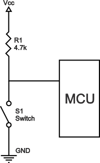
Pull-up resistors are not a special kind of resistors; they are simple fixed-value resistors connected between the voltage supply (usually +5V) and the appropriate pin, which results in defining the input or output voltage in the absence of a driving signal. A typical pull-up resistor value is 4.7kΩ, but can vary depending on the application, as will be discussed later in this article.

Pull-up resistor definition

Pull-up resistors are resistors which are used to ensure that a wire is pulled to a high logical level in the absence of an input signal.

What are pull-down resistors?

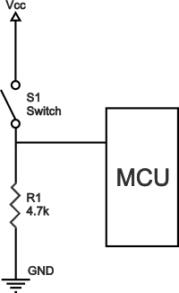
Pull-down resistors work in the same manner as pull-up resistors, except that they pull the pin to a logical low value. They are connected between ground and the appropriate pin on a device. An example of a pull-down resistor in a digital circuit can be seen in the figure. A pushbutton switch is connected between the supply voltage and a microcontroller pin. In such a circuit, when the switch is closed, the micro-controller input is at a logical high value, but when the switch is open, the pull-down resistor pulls the input voltage down to ground (logical zero value), preventing an undefined state at the input. The pull-down resistor must have a larger resistance than the impedance of the logic circuit, or else it might be able to pull the voltage down by too much and the input voltage at the pin would remain at a constant logical low value – regardless of the switch position.

Pull-up resistor value

The appropriate value for the pull-up resistor is limited by two factors. The first factor is power dissipation. If the resistance value is too low, a high current will flow through the pull-up resistor, heating the device and using up an unnecessary amount of power when the switch is closed. This condition is called a strong pull-up and is avoided when low power consumption is a requirement. The second factor is the pin voltage when the switch is open. If the pull-up resistance value is too high, combined with a large leakage current of the input pin, the input voltage can become insufficient when the switch is open. This condition is called having a weak pull-up. The actual value of the pull-up’s resistance depends on the impedance of the input pin, which is closely related to the pin’s leakage current.

A rule of thumb is to use a resistor that is at least 10 times smaller than the value of the input pin impedance. In bipolar logic families which operate at operating at 5V, the typical pull-up resistor value is 1-5 kΩ. For switch and resistive sensor applications, the typical pull-up resistor value is 1-10 kΩ. If in doubt, a good starting point when using a switch is 4.7 kΩ. Some digital circuits, such as CMOS families, have a small input leakage current, allowing much higher resistance values, from around 10kΩ up to 1MΩ. The disadvantage when using a larger resistance value is that the input pin responses to voltage changes slower. This is the result of the coupling between the pull-up resistor and the line capacitance of the wire which forms an RC circuit. The larger the product of R and C, the more time is needed for the capacitance to charge and discharge, and consequently the slower the circuit. In high-speed circuits, a large pull-up resistor can sometimes limit the speed at which the pin can reliably change state.

Typical applications for pull-up and pull-down resistors

Pull-up and pull-down resistors are often used when interfacing a switch or some other input with a microcontroller or other digital gates. Most microcontrollers have in-built programmable pull up/down resistors so fewer external components are needed. It is possible to interface a switch with such microcontrollers directly. Pull-up resistors are in general used more often than pull-down resistors, although some microcontroller families have both pull-up and pull-downs available.
They are often used in analog to digital converters to provide a controlled current flow into a resistive sensor.
Another application is the I2C protocol bus, where pull-up resistors are used to enable a single pin to act as an input or an output. When not connected to a bus, the pin floats in a high-impedance state.
Pull-down resistors are also used on outputs to provide a known output impedance.

//----------------------------------------------------------------------------- // Includes //----------------------------------------------------------------------------- #include <SI_C8051F300_Register_Enums.h> #include <stdio.h> //----------------------------------------------------------------------------- // Global CONSTANTS //----------------------------------------------------------------------------- #define SYSCLK 24500000 // SYSCLK frequency in Hz #define BAUDRATE 115200 // Baud rate of UART in bps SI_SBIT(DE_RE, SFR_P0, 6); //定義P0.6 控制名稱為DE_RE SI_SBIT(LED2, SFR_P0, 1); //定義P0.1 控制名稱為LED2 SI_SBIT(LED1, SFR_P0, 0); //定義P0.0 控制名稱為LED1 SI_SBIT(LED3, SFR_P0, 2); //定義P0.2 控制名稱為LED3 SI_SBIT(LED4, SFR_P0, 3); //定義P0.3 控制名稱為LED4 SI_SBIT(LED5, SFR_P0, 7); //定義P0.7 控制名稱為LED5 //----------------------------------------------------------------------------- // Function PROTOTYPES //----------------------------------------------------------------------------- SI_INTERRUPT_PROTO(UART0_Interrupt, 4); void SYSCLK_Init (void); void UART0_Init (void); void PORT_Init (void); void Timer2_Init (int16_t); void MyDelay (uint16_t Value); #define KEY_DOWN 1 #define KEY_UP 0 #define LED_ON 0 #define LED_OFF 1 //----------------------------------------------------------------------------- // Global Variables //----------------------------------------------------------------------------- #define UART_BUFFERSIZE 6 uint8_t UART_Buffer[UART_BUFFERSIZE]; uint8_t UART_Buffer_Size = 0; uint8_t UART_Input_First = 0; uint8_t UART_Output_First = 0; uint8_t TX_Ready =1; uint8_t RX_Ready =0; static char Byte; uint8_t SnapDown_TimeCnt =0; uint8_t fSnap = 0; uint8_t RecDown_TimeCnt =0; uint8_t fRec = 0; //----------------------------------------------------------------------------- // SiLabs_Startup() Routine // ---------------------------------------------------------------------------- // This function is called immediately after reset, before the initialization // code is run in SILABS_STARTUP.A51 (which runs before main() ). This is a // useful place to disable the watchdog timer, which is enable by default // and may trigger before main() in some instances. //----------------------------------------------------------------------------- void SiLabs_Startup (void) { PCA0MD &= ~0x40; // WDTE = 0 (clear watchdog timer } //----------------------------------------------------------------------------- // MAIN Routine //----------------------------------------------------------------------------- void main (void) { // enable) PORT_Init(); // Initialize Port I/O SYSCLK_Init (); // Initialize Oscillator UART0_Init(); IE_EA = 1; DE_RE =0; Timer2_Init (SYSCLK / 12 / 1000); // Init Timer2 to generate // 每1ms 計時中斷 while(1) { if(RX_Ready) { RX_Ready = 0; UART_Buffer_Size =0; if(UART_Buffer[3]==0x01)//任一鍵按下 { if(UART_Buffer[4]==0x01)//REC { fRec = KEY_DOWN; RecDown_TimeCnt=0; } else if(UART_Buffer[4]==0x02)//SNAP { fSnap = KEY_DOWN; SnapDown_TimeCnt=0; } else if(UART_Buffer[4]==0x03)//LED UP LED3 = LED_ON; else if(UART_Buffer[4]==0x04)//LED DO LED4 = LED_ON; else if(UART_Buffer[4]==0x05)//Mirror LED5 = LED_ON; } if(UART_Buffer[3]==0x00)//任一鍵放開 { if(UART_Buffer[4]==0x01)//REC { fRec = KEY_UP; } else if(UART_Buffer[4]==0x02)//SNAP { fSnap = KEY_UP; } else if(UART_Buffer[4]==0x03)//LED UP LED3 = LED_OFF; else if(UART_Buffer[4]==0x04)//LED DO LED4 = LED_OFF; else if(UART_Buffer[4]==0x05)//Mirror LED5 = LED_OFF; } IE_ES0 =1; } if(SnapDown_TimeCnt >55 && fSnap == KEY_DOWN) { LED1 = LED_ON; } else if(SnapDown_TimeCnt >55 && fSnap == KEY_UP) { LED1 =LED_OFF; SnapDown_TimeCnt =0; } else if(SnapDown_TimeCnt >45 && SnapDown_TimeCnt <55 && fSnap == KEY_UP) { LED1 = LED_ON; LED2 = LED_ON; MyDelay(1100);//延遲約0.5秒 LED1 = LED_OFF; LED2 = LED_OFF; SnapDown_TimeCnt =0; } if(RecDown_TimeCnt >55 && fRec == KEY_DOWN) { LED2 = LED_ON; } else if(RecDown_TimeCnt >55 && fRec == KEY_UP) { LED2 = LED_OFF; RecDown_TimeCnt =0; } else if(RecDown_TimeCnt >45 && RecDown_TimeCnt <55 && fRec == KEY_UP) { LED4 = LED_ON; LED5 = LED_ON; MyDelay(1100);//延遲約0.5秒 LED4 = LED_OFF; LED5 = LED_OFF; RecDown_TimeCnt =0; } } } //----------------------------------------------------------------------------- // Initialization Subroutines //----------------------------------------------------------------------------- //----------------------------------------------------------------------------- // PORT_Init //----------------------------------------------------------------------------- // // Return Value : None // Parameters : None // // Configure the Crossbar and GPIO ports. // // P0.4 digital push-pull UART TX // P0.5 digital open-drain UART RX // //----------------------------------------------------------------------------- void PORT_Init (void) { P0MDOUT |= 0x10; // set UART TX to push-pull output XBR1 = 0x03; // Enable UTX, URX as push-pull output XBR2 = 0x40; // Enable crossbar, weak pull-ups // disabled XBR0 = 0x40; P0MDOUT |= 0x40; } //----------------------------------------------------------------------------- // SYSCLK_Init //----------------------------------------------------------------------------- // // Return Value : None // Parameters : None // // This routine initializes the system clock to use the internal oscillator // at its maximum frequency. // Also enables the Missing Clock Detector. //----------------------------------------------------------------------------- void SYSCLK_Init (void) { OSCICN |= 0x03; // Configure internal oscillator for // its maximum frequency RSTSRC = 0x04; // Enable missing clock detector } //----------------------------------------------------------------------------- // UART0_Init //----------------------------------------------------------------------------- // // Return Value : None // Parameters : None // // Configure the UART0 using Timer1, for <BAUDRATE> and 8-N-1. //----------------------------------------------------------------------------- void UART0_Init (void) { SCON0 = 0x10; // SCON0: 8-bit variable bit rate // level of STOP bit is ignored // RX enabled // ninth bits are zeros // clear SCON0_RI and SCON0_TI bits if (SYSCLK/BAUDRATE/2/256 < 1) { TH1 = -(SYSCLK/BAUDRATE/2); CKCON |= 0x10; // T1M = 1; SCA1:0 = xx } else if (SYSCLK/BAUDRATE/2/256 < 4) { TH1 = -(SYSCLK/BAUDRATE/2/4); CKCON |= 0x01; // T1M = 0; SCA1:0 = 01 CKCON &= ~0x12; } else if (SYSCLK/BAUDRATE/2/256 < 12) { TH1 = -(SYSCLK/BAUDRATE/2/12); CKCON &= ~0x13; // T1M = 0; SCA1:0 = 00 } else { TH1 = -(SYSCLK/BAUDRATE/2/48); CKCON |= 0x02; // T1M = 0; SCA1:0 = 10 CKCON &= ~0x11; } TL1 = 0xff; // set Timer1 to overflow immediately TMOD |= 0x20; // TMOD: timer 1 in 8-bit autoreload TMOD &= ~0xD0; // mode TCON_TR1 = 1; // START Timer1 TX_Ready = 1; // Flag showing that UART can transmit IP |= 0x10; // Make UART high priority IE_ES0 = 1; // Enable UART0 interrupts } //----------------------------------------------------------------------------- // Interrupt Service Routines //----------------------------------------------------------------------------- //----------------------------------------------------------------------------- // UART0_Interrupt //----------------------------------------------------------------------------- // // This routine is invoked whenever a character is entered or displayed on the // Hyperterminal. // //----------------------------------------------------------------------------- SI_INTERRUPT(UART0_Interrupt, 4) { if (SCON0_RI == 1) { if( UART_Buffer_Size == 0) { // If new word is entered UART_Input_First = 0; } SCON0_RI = 0; // Clear interrupt flag Byte = SBUF0; // Read a character from UART if (UART_Buffer_Size < UART_BUFFERSIZE) { UART_Buffer[UART_Input_First] = Byte; // Store in array UART_Buffer_Size++; // Update array's size UART_Input_First++; // Update counter } if(UART_Buffer_Size >= UART_BUFFERSIZE) { RX_Ready =1; UART_Buffer_Size =0; IE_ES0 = 0; } } if (SCON0_TI == 1) // Check if transmit flag is set { SCON0_TI = 0; // Clear interrupt flag if (UART_Buffer_Size != 1) // If buffer not empty { // If a new word is being output if ( UART_Buffer_Size == UART_Input_First ) { UART_Output_First = 0; } // Store a character in the variable byte Byte = UART_Buffer[UART_Output_First]; if ((Byte >= 0x61) && (Byte <= 0x7A)) { // If upper case letter Byte -= 32; } SBUF0 = Byte; // Transmit to Hyperterminal UART_Output_First++; // Update counter UART_Buffer_Size--; // Decrease array size } else { UART_Buffer_Size = 0; // Set the array size to 0 TX_Ready = 1; // Indicate transmission complete } } } //----------------------------------------------------------------------------- // Timer2_Init //----------------------------------------------------------------------------- // // Configure Timer2 to 16-bit auto-reload and generate an interrupt at // interval specified by <counts> using SYSCLK/12 as its time base. // void Timer2_Init (int16_t counts) { TMR2CN = 0x00; // Stop Timer2; Clear TF2; // use SYSCLK/12 as timebase CKCON &= ~(CKCON_T2MH__BMASK | CKCON_T2ML__BMASK ); // Timer2 clocked based on TMR2CN_T2XCLK TMR2RL = -counts; // Init reload values TMR2 = 0xffff; // set to reload immediately IE_ET2 = 1; // enable Timer2 interrupts TMR2CN_TR2 = 1; // start Timer2 } //----------------------------------------------------------------------------- // Timer2_ISR //----------------------------------------------------------------------------- // This routine changes the state of the LED whenever Timer2 overflows. // SI_INTERRUPT(Timer2_ISR, TIMER2_IRQn) { TMR2CN_TF2H = 0; // clear Timer2 interrupt flag if(fSnap == KEY_DOWN) { SnapDown_TimeCnt++; // change state of LED if(SnapDown_TimeCnt==255) SnapDown_TimeCnt = 254; } else if(fRec == KEY_DOWN) { RecDown_TimeCnt++; // change state of LED if(RecDown_TimeCnt==255) RecDown_TimeCnt = 254; } } void MyDelay(uint16_t Value) { uint16_t i,j; for(i=0;i<Value;i++) { for(j=0;j<1000;j++) _nop_(); } } //----------------------------------------------------------------------------- // End Of File //-----------------------------------------------------------------------------
最新发布
07-04
评论
添加红包

请填写红包祝福语或标题

红包个数最小为10个

红包金额最低5元

当前余额3.43前往充值 >
需支付:10.00
成就一亿技术人!
领取后你会自动成为博主和红包主的粉丝 规则
hope_wisdom
发出的红包
实付
使用余额支付
点击重新获取
扫码支付
钱包余额 0

抵扣说明:

1.余额是钱包充值的虚拟货币,按照1:1的比例进行支付金额的抵扣。
2.余额无法直接购买下载,可以购买VIP、付费专栏及课程。

余额充值