


INA226 是德州仪器 (TI) 的一款 IC,可以轻松、超精确地测量电流、电压和功率。 接口为 I2
。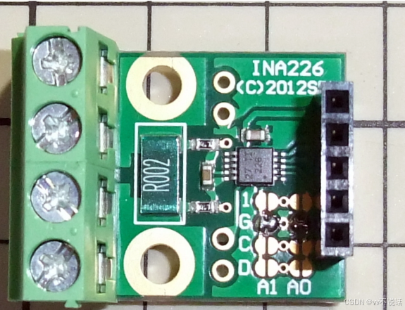
可以获取四种类型的电压:电压 (Bus Voltage)、分流电阻电压 (Shunt Voltage)、电流 (Current) 和功率 (Power)。 功率、分流电压→电流的转换和平均处理由 IC 内部完成。 为了计算电流和功率,必须在初始化时将分流电阻常数写入校准寄存器。 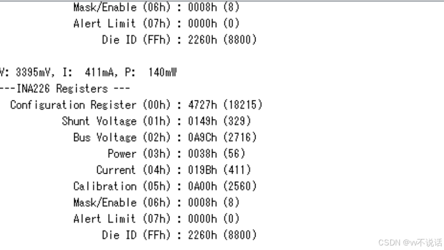
#include <Wire.h>

#define NELEMS(arg) (sizeof(arg) / sizeof((arg)[0]))

const int   INA226_ADDR         = 0x40;                 // INA226 I2C Address (A0=A1=GND)
const word  INA226_CAL_VALUE    = 0x0A00;               // INA226 Calibration Register Value

// INA226 Registers
#define INA226_REG_CONFIGURATION_REG            0x00    // Configuration Register (R/W)
#define INA226_REG_SHUNT_VOLTAGE                0x01    // Shunt Voltage (R)
#define INA226_REG_BUS_VOLTAGE                  0x02    // Bus Voltage (R)
#define INA226_REG_POWER                        0x03    // Power (R)
#define INA226_REG_CURRENT                      0x04    // Current (R)
#define INA226_REG_CALIBRATION                  0x05    // Calibration (R/W)
#define INA226_REG_MASK_ENABLE                  0x06    // Mask/Enable (R/W)
#define INA226_REG_ALERT_LIMIT                  0x07    // Alert Limit (R/W)
#define INA226_REG_DIE_ID                       0xFF    // Die ID (R)

// Operating Mode (Mode Settings [2:0])
#define INA226_CONF_MODE_POWER_DOWN             (0<<0)  // Power-Down
#define INA226_CONF_MODE_TRIG_SHUNT_VOLTAGE     (1<<0)  // Shunt Voltage, Triggered
#define INA226_CONF_MODE_TRIG_BUS_VOLTAGE       (2<<0)  // Bus Voltage, Triggered
#define INA226_CONF_MODE_TRIG_SHUNT_AND_BUS     (3<<0)  // Shunt and Bus, Triggered
#define INA226_CONF_MODE_POWER_DOWN2            (4<<0)  // Power-Down
#define INA226_CONF_MODE_CONT_SHUNT_VOLTAGE     (5<<0)  // Shunt Voltage, Continuous
#define INA226_CONF_MODE_CONT_BUS_VOLTAGE       (6<<0)  // Bus Voltage, Continuous
#define INA226_CONF_MODE_CONT_SHUNT_AND_BUS     (7<<0)  // Shunt and Bus, Continuous (default)

// Shunt Voltage Conversion Time (VSH CT Bit Settings [5:3])
#define INA226_CONF_VSH_140uS                   (0<<3)  // 140us
#define INA226_CONF_VSH_204uS                   (1<<3)  // 204us
#define INA226_CONF_VSH_332uS                   (2<<3)  // 332us
#define INA226_CONF_VSH_588uS                   (3<<3)  // 588us
#define INA226_CONF_VSH_1100uS                  (4<<3)  // 1.1ms (default)
#define INA226_CONF_VSH_2116uS                  (5<<3)  // 2.116ms
#define INA226_CONF_VSH_4156uS                  (6<<3)  // 4.156ms
#define INA226_CONF_VSH_8244uS                  (7<<3)  // 8.244ms

// Bus Voltage Conversion Time (VBUS CT Bit Settings [8:6])
#define INA226_CONF_VBUS_140uS                  (0<<6)  // 140us
#define INA226_CONF_VBUS_204uS                  (1<<6)  // 204us
#define INA226_CONF_VBUS_332uS                  (2<<6)  // 332us
#define INA226_CONF_VBUS_588uS                  (3<<6)  // 588us
#define INA226_CONF_VBUS_1100uS                 (4<<6)  // 1.1ms (default)
#define INA226_CONF_VBUS_2116uS                 (5<<6)  // 2.116ms
#define INA226_CONF_VBUS_4156uS                 (6<<6)  // 4.156ms
#define INA226_CONF_VBUS_8244uS                 (7<<6)  // 8.244ms

// Averaging Mode (AVG Bit Settings[11:9])
#define INA226_CONF_AVG_1                       (0<<9)  // 1 (default)
#define INA226_CONF_AVG_4                       (1<<9)  // 4
#define INA226_CONF_AVG_16                      (2<<9)  // 16
#define INA226_CONF_AVG_64                      (3<<9)  // 64
#define INA226_CONF_AVG_128                     (4<<9)  // 128
#define INA226_CONF_AVG_256                     (5<<9)  // 256
#define INA226_CONF_AVG_512                     (6<<9)  // 512
#define INA226_CONF_AVG_1024                    (7<<9)  // 1024

// Reset Bit (RST bit [15])
#define INA226_CONF_RESET_ACTIVE                (1<<15)
#define INA226_CONF_RESET_INACTIVE              (0<<15)

static void writeRegister(byte reg, word value)
{
  Wire.beginTransmission(INA226_ADDR);
  Wire.write(reg);
  Wire.write((value >> 8) & 0xFF);
  Wire.write(value & 0xFF);
  Wire.endTransmission();
}

static void setupRegister(void)
{
  writeRegister(INA226_REG_CONFIGURATION_REG,
        INA226_CONF_RESET_INACTIVE
      | INA226_CONF_MODE_CONT_SHUNT_AND_BUS
      | INA226_CONF_VSH_1100uS
      | INA226_CONF_VBUS_1100uS
      | INA226_CONF_AVG_64
      );

  writeRegister(INA226_REG_CALIBRATION, INA226_CAL_VALUE);
}

static word readRegister(byte reg)
{
  word res = 0x0000;

  Wire.beginTransmission(INA226_ADDR);
  Wire.write(reg);

  if(Wire.endTransmission() == 0) {
    if(Wire.requestFrom(INA226_ADDR, 2) >= 2) {
      res = Wire.read() * 256;
      res += Wire.read();
    }
  }

  return res;
}

typedef struct tagREG_INFO {
  byte	reg;
  const char*	name;
}REG_INFO;

const static REG_INFO   st_aRegs[] = {
  { INA226_REG_CONFIGURATION_REG,   "Configuration Register"    },
  { INA226_REG_SHUNT_VOLTAGE,       "Shunt Voltage"             },
  { INA226_REG_BUS_VOLTAGE,         "Bus Voltage"               },
  { INA226_REG_POWER,               "Power"                     },
  { INA226_REG_CURRENT,             "Current"                   },
  { INA226_REG_CALIBRATION,         "Calibration"               },
  { INA226_REG_MASK_ENABLE,         "Mask/Enable"               },
  { INA226_REG_ALERT_LIMIT,         "Alert Limit"               },
  { INA226_REG_DIE_ID,              "Die ID"                    },
};

static void dumpRegisters(void)
{
  int i;
  const REG_INFO* pInfo;
  static word REGS[NELEMS(st_aRegs)];
  static char  buf[64];

  for(i = 0; i < NELEMS(REGS); i++) {
    pInfo = &st_aRegs[i];
    REGS[i] = readRegister(pInfo->reg);
  }

  Serial.println("---INA226 Registers ---");

  for(i = 0; i < NELEMS(REGS); i++) {
    pInfo = &st_aRegs[i];
    snprintf(buf, NELEMS(buf), "%24s (%02Xh) : %04Xh (%u)", pInfo->name, pInfo->reg, REGS[i], REGS[i]);
    Serial.println(buf);
  }
}

void setup()
{
  // Initialize I2C with IO22 as SCL and IO21 as SDA
  Wire.begin(21, 22);
  Serial.begin(9600);

  setupRegister();
}

void loop()
{
  char  buf[64];
  long  voltage;   // Bus Voltage (mV)
  short current;   // Current (mA)
  long  power;     // Power (uW)

  voltage  = (long)((short)readRegister(INA226_REG_BUS_VOLTAGE)) * 1250L;    // LSB=1.25mV
  current  = (short)readRegister(INA226_REG_CURRENT);
  power    = (long)readRegister(INA226_REG_POWER) * 25000L;                  // LSB=25mW

  Serial.println();
  snprintf(buf, NELEMS(buf)
    , "V:%5ldmV, I:%5dmA, P:%5ldmW"
    , (voltage + (1000/2)) / 1000
    , current
    , (power + (1000/2)) / 1000
    );

  Serial.println(buf);

  dumpRegisters();

  delay(1000);
}


 2261
2261

 被折叠的 条评论
为什么被折叠?
被折叠的 条评论
为什么被折叠?
 到【灌水乐园】发言


