


1.配置各个物理口的IP地址
PC1:192.168.1.1
PC2:192.168.4.1
PC3:192.168.2.1
PC4:192.168.3.1
[R1]int g0/0/0
[R1-GigabitEthernet0/0/0]ip add 192.168.1.254 24
Mar 30 2024 14:10:40-08:00 R1 %%01IFNET/4/LINK_STATE(l)[0]:The line protocol IP
on the interface GigabitEthernet0/0/0 has entered the UP state.
[R1-GigabitEthernet0/0/0]int s4/0/0
[R1-Serial4/0/0]ip add 15.1.1.1 24
[R1-Serial4/0/0]q
[R1]
[R2]int g0/0/0
[R2-GigabitEthernet0/0/0]ip add 192.168.2.254 24
Mar 30 2024 14:15:30-08:00 R2 %%01IFNET/4/LINK_STATE(l)[0]:The line protocol IP
on the interface GigabitEthernet0/0/0 has entered the UP state.
[R2-GigabitEthernet0/0/0]int s4/0/0
[R2-Serial4/0/0]ip add 25.1.1.2 24
[R2-Serial4/0/0]q
[R2]
[R3]int g0/0/0
[R3-GigabitEthernet0/0/0]ip add 192.168.3.254 24
Mar 30 2024 14:17:07-08:00 R3 %%01IFNET/4/LINK_STATE(l)[0]:The line protocol IP
on the interface GigabitEthernet0/0/0 has entered the UP state.
[R3-GigabitEthernet0/0/0]int s4/0/0
[R3-Serial4/0/0]ip add 35.1.1.3 24
[R3-Serial4/0/0]q
[R3]
[R4]int g0/0/1
[R4-GigabitEthernet0/0/1]ip add 192.168.4.254 24
Mar 30 2024 14:18:57-08:00 R4 %%01IFNET/4/LINK_STATE(l)[0]:The line protocol IP
on the interface GigabitEthernet0/0/1 has entered the UP state.
[R4-GigabitEthernet0/0/1]int g 0/0/0
[R4-GigabitEthernet0/0/0]ip add 45.1.1.4 24
Mar 30 2024 14:19:26-08:00 R4 %%01IFNET/4/LINK_STATE(l)[1]:The line protocol IP
on the interface GigabitEthernet0/0/0 has entered the UP state.
[R4-GigabitEthernet0/0/0]q
[R5]int s 4/0/1
[R5-Serial4/0/1]ip add 15.1.1.5 24
[R5-Serial4/0/1]
Mar 30 2024 14:21:31-08:00 R5 %%01IFNET/4/LINK_STATE(l)[0]:The line protocol PPP
IPCP on the interface Serial4/0/1 has entered the UP state.
[R5-Serial4/0/1]int s 3/0/1
[R5-Serial3/0/1]ip add 25.1.1.5 24
[R5-Serial3/0/1]
Mar 30 2024 14:21:53-08:00 R5 %%01IFNET/4/LINK_STATE(l)[1]:The line protocol PPP
IPCP on the interface Serial3/0/1 has entered the UP state.
[R5-Serial3/0/1]int s 4/0/0
[R5-Serial4/0/0]ip add 35.1.1.5 24
[R5-Serial4/0/0]
Mar 30 2024 14:22:23-08:00 R5 %%01IFNET/4/LINK_STATE(l)[2]:The line protocol PPP
IPCP on the interface Serial4/0/0 has entered the UP state.
[R5-Serial4/0/0]int g0/0/0
[R5-GigabitEthernet0/0/0]ip add 45.1.1.5 24
Mar 30 2024 14:23:17-08:00 R5 %%01IFNET/4/LINK_STATE(l)[3]:The line protocol IP
on the interface GigabitEthernet0/0/0 has entered the UP state.
[R5-GigabitEthernet0/0/0]q
[R5]
[R5]int l0
[R5-LoopBack0]ip add 5.5.5.5 24
[R5-LoopBack0]
2.通公网
静态缺省
[R1]ip route-static 0.0.0.0 0 15.1.1.5
[R2]ip route-static 0.0.0.0 0 25.1.1.5
[R3]ip route-static 0.0.0.0 0 35.1.1.5
[R4]ip route-static 0.0.0.0 0 45.1.1.5
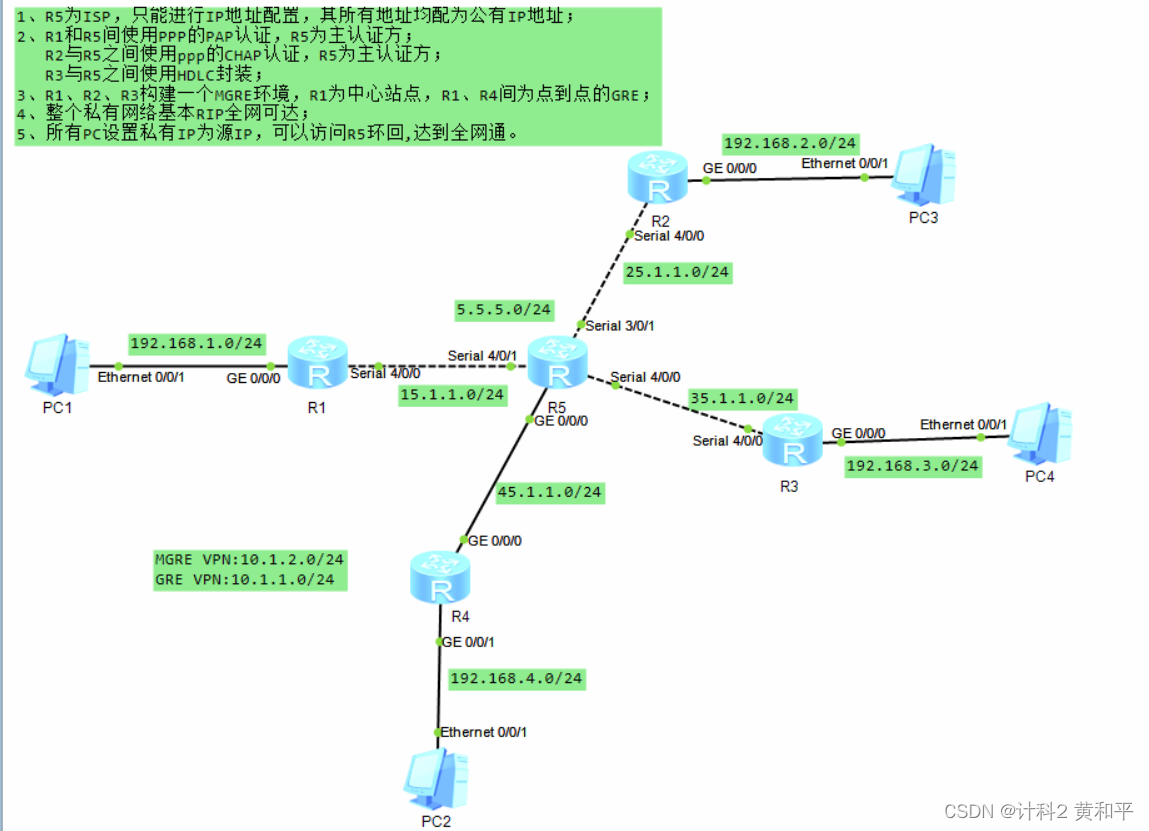
3.R1和R5之间使用PPP的PAP认证,R5为主认证方
(1)主认证方:
[R5]aaa
[R5-aaa]local-user hhp password cipher 12345
Info: Add a new user.
[R5-aaa]local-user hhp service-type ppp
[R5-aaa]q
[R5]
[R5]int s4/0/1
[R5-Serial4/0/1]ppp authentication-mode PAP
[R5-Serial4/0/1]q
[R5]
(2)被认证方:
[R1]int s4/0/0
[R1-Serial4/0/0]ppp pap local-user hhp password cipher 12345
[R1-Serial4/0/0]q
[R1]
4.R2和R5之间使用PPP的chap认证,R5为主认证方
(1)主认证方:
[R5]aaa
[R5-aaa]local-user hhp2 password cipher 123456
Info: Add a new user.
[R5-aaa]local-user hhp2 service-type ppp
[R5-aaa]q
[R5]int s3/0/1
[R5-Serial3/0/1]ppp authentication-mode chap
[R5-Serial3/0/1]q
[R5]
(2)被认证方:
[R2]int s 4/0/0
[R2-Serial4/0/0]ppp chap user hhp2
[R2-Serial4/0/0]ppp chap password cipher 123456
5.R3与R5之间使用HDLC封装
(1)R3上的配置:
[R3]int s4/0/0
[R3-Serial4/0/0]link-p
[R3-Serial4/0/0]link-protocol hdlc
Warning: The encapsulation protocol of the link will be changed. Continue? [Y/N]
:y
(2)R5上的配置:
[R5]int s4/0/0
[R5-Serial4/0/0]link-protocol Hdlc
Warning: The encapsulation protocol of the link will be changed. Continue? [Y/N]
:y
6.R1,R2,R3,构成一个MGRE环境,R1为站点中心;
MGRE VPN:10.1.2.0/24
创建隧道Tunnel 0/0/0,并加入到同一个nhrp中,配置如下:
[R1]int Tunnel 0/0/0
[R1-Tunnel0/0/0]ip add 10.1.2.1 24
[R1-Tunnel0/0/0]tunnel-protocol gre p2mp
[R1-Tunnel0/0/0]source 15.1.1.1
Mar 30 2024 15:09:20-08:00 R1 %%01IFNET/4/LINK_STATE(l)[0]:The line protocol IP
on the interface Tunnel0/0/0 has entered the UP state.
[R1-Tunnel0/0/0]
[R1-Tunnel0/0/0]nhrp network-id 100
[R2]int Tunnel 0/0/0
[R2-Tunnel0/0/0]ip add 10.1.2.2 24
[R2-Tunnel0/0/0]tunnel-protocol gre p2mp
[R2-Tunnel0/0/0]source Serial 4/0/0
Mar 30 2024 15:12:37-08:00 R2 %%01IFNET/4/LINK_STATE(l)[0]:The line protocol IP
on the interface Tunnel0/0/0 has entered the UP state.
[R2-Tunnel0/0/0]nhrp network-id 100
[R2-Tunnel0/0/0]
[R3]int Tunnel 0/0/0
[R3-Tunnel0/0/0]ip add 10.1.2.3 24
[R3-Tunnel0/0/0]tunnel-protocol gre p2mp
[R3-Tunnel0/0/0]source Serial 4/0/0
Mar 30 2024 15:16:13-08:00 R3 %%01IFNET/4/LINK_STATE(l)[0]:The line protocol IP
on the interface Tunnel0/0/0 has entered the UP state.
[R3-Tunnel0/0/0]nhrp network-id 100
[R3-Tunnel0/0/0]
7.R1,R4之间为点到点GRE
GRE VPN:10.1.1.0/24
[R1]int Tunnel 0/0/1
[R1-Tunnel0/0/1]ip add 10.1.1.1 24
[R1-Tunnel0/0/1]tunnel-protocol gre
[R1-Tunnel0/0/1]source 15.1.1.1
[R1-Tunnel0/0/1]destination 45.1.1.4
[R1-Tunnel0/0/1]
[R4]int Tunnel 0/0/1
[R4-Tunnel0/0/1]ip add 10.1.1.4 24
[R4-Tunnel0/0/1]tunnel-protocol gre
[R4-Tunnel0/0/1]source 45.1.1.4
[R4-Tunnel0/0/1]destination 15.1.1.1
[R4-Tunnel0/0/1]q
8.整个私有网络通过rip路由协议全网互通
[R1]rip 1
[R1-rip-1]v 2
[R1-rip-1]undo summary
[R1-rip-1]network 192.168.1.0
[R1-rip-1]network 10.0.0.0
[R1-rip-1]
[R2]rip 1
[R2-rip-1]v 2
[R2-rip-1]undo summary
[R2-rip-1]network 192.168.2.0
[R2-rip-1]network 10.0.0.0
[R2-rip-1]
[R3]rip 1
[R3-rip-1]v 2
[R3-rip-1]undo summary
[R3-rip-1]network 192.168.3.0
[R3-rip-1]network 10.0.0.0
[R3-rip-1]
[R4]rip 1
[R4-rip-1]v 2
[R4-rip-1]undo summary
[R4-rip-1]network 192.168.4.0
[R4-rip-1]network 10.0.0.0
[R4-rip-1]
中心站点开启隧道的广播功能:
[R1]int Tunnel 0/0/0
[R1-Tunnel0/0/0]nhrp entry multicast dynamic
[R1-Tunnel0/0/0]q
其他的 向中心站点 开启注册:
[R2]int Tunnel 0/0/0
[R2-Tunnel0/0/0]nhrp entry 10.1.2.1 15.1.1.1 register
[R3]int Tunnel 0/0/0
[R3-Tunnel0/0/0]nhrp entry 10.1.2.1 15.1.1.1 register
关闭mgre水平分割机制
[R1-Tunnel0/0/0]undo rip split-horizon
[R2-Tunnel0/0/0]undo rip split-horizon
[R3-Tunnel0/0/0]undo rip split-horizon
9.所有PC设置私有IP为源IP,可以访问R5环回,达到全网通
[R1]acl 2000
[R1-acl-basic-2000]rule permit source 192.168.1.0 0.0.0.255
[R1-acl-basic-2000]q
[R1]
[R1]int Serial 4/0/0
[R1-Serial4/0/0]nat outbound 2000
[R1-Serial4/0/0]
[R2]acl 2000
[R2-acl-basic-2000]rule permit source 192.168.2.0 0.0.0.255
[R2-acl-basic-2000]q
[R2]int s 4/0/0
[R2-Serial4/0/0]nat outbound 2000
[R2-Serial4/0/0]
[R3]acl 2000
[R3-acl-basic-2000]rule permit source 192.168.3.0 0.0.0.255
[R3-acl-basic-2000]q
[R3]int s 4/0/0
[R3-Serial4/0/0]nat outbound 2000
[R3-Serial4/0/0]
[R4]acl 2000
[R4-acl-basic-2000]rule permit source 192.168.4.0 0.0.0.255
[R4-acl-basic-2000]q
[R4]int g 0/0/0
[R4-GigabitEthernet0/0/0]nat outbound 2000
[R4-GigabitEthernet0/0/0]


 1万+
1万+

 被折叠的 条评论
为什么被折叠?
被折叠的 条评论
为什么被折叠?
 到【灌水乐园】发言


