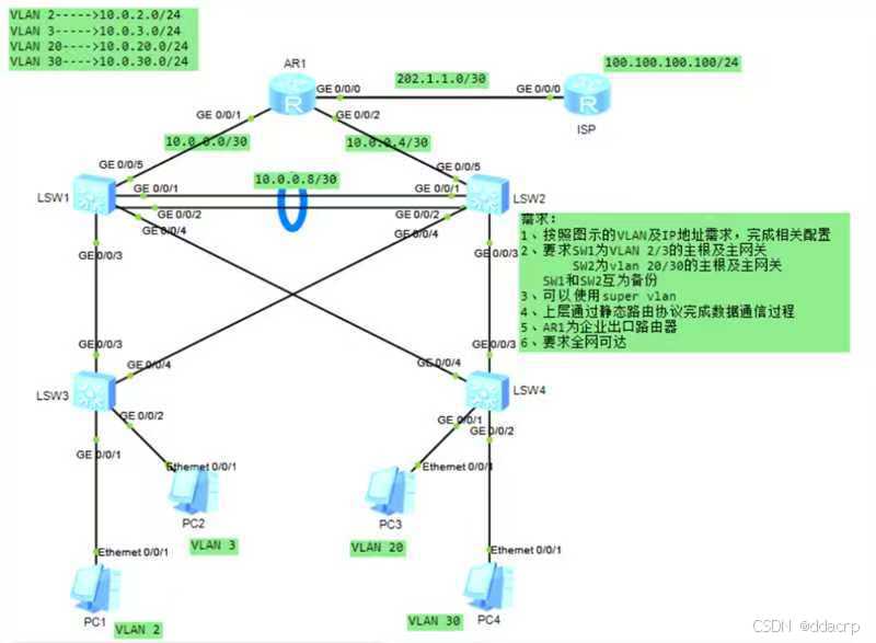
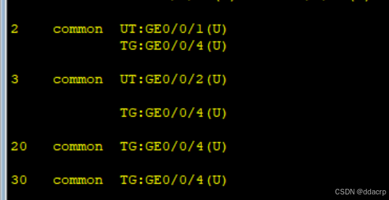
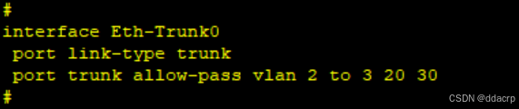
第一步:对于接入层设备LSW3,LSW4,汇聚层LSW1,LSW2, 创建vlan2,3,20,30,并进行相应的配置。以LSW3为例,最终的效果如下: 需要注意的是,要先对LSW1,LSW2进行链路聚合再进行相关的VLAN配置。以LSW1的g0/0/1和g0/0/2为例,结果如下: 第二步:配置主根,使用MSTP。 1.模式改为mstp,创建实例1(vlan2和vlan3)和实例2(vlan20和vlan30),LSW1,2,3,4配置命令都是: stp enable stp mode mstp stp region-configuration region-name aa revision-level 100 instance 1 vlan 2 to 3 instance 2 vlan 20 30 active region-configuration 2.配置LSW1,LSW2中实例1和实例2 的优先级: 在LSW1中: stp instance 1 root primary stp instance 2 root secondary 在LSW2中: stp instance 1 root secondary stp instance 2 root primary 第三步:配置网关,使用VRRP 1.VLAN2以LSW1为主网关,以LSW2为备用网关 在LSW1中: interface Vlanif2 ip address 10.0.2.1 255.255.255.0 vrrp vrid 1 virtual-ip 10.0.2.254 vrrp vrid 1 priority 120 vrrp vrid 1 track interface GigabitEthernet0/0/5 reduced 30 在LSW2中: interface Vlanif2 ip address 10.0.2.1 255.255.255.0 vrrp vrid 1 virtual-ip 10.0.2.254 1.VLAN2以LSW1为主网关,以LSW2为备用网关 在LSW1中: interface Vlanif2 ip address 10.0.2.1 255.255.255.0 vrrp vrid 1 virtual-ip 10.0.2.254 vrrp vrid 1 priority 120 vrrp vrid 1 track interface GigabitEthernet0/0/5 reduced 30 在LSW2中: interface Vlanif2 ip address 10.0.2.2 255.255.255.0 vrrp vrid 1 virtual-ip 10.0.2.254 2.VLAN3以LSW1为主网关,以LSW2为备用网关 在LSW1中: interface Vlanif3 ip address 10.0.3.1 255.255.255.0 vrrp vrid 1 virtual-ip 10.0.3.254 vrrp vrid 1 priority 120 vrrp vrid 1 track interface GigabitEthernet0/0/5 reduced 30 在LSW2中: interface Vlanif3 ip address 10.0.3.2 255.255.255.0 vrrp vrid 1 virtual-ip 10.0.3.254 3.VLAN20以LSW2为主网关,以LSW1为备用网关 在LSW2中: interface Vlanif20 ip address 10.0.20.2 255.255.255.0 vrrp vrid 1 virtual-ip 10.0.20.254 vrrp vrid 1 priority 120 vrrp vrid 1 track interface GigabitEthernet0/0/5 reduced 30 在LSW1中: interface Vlanif20 ip address 10.0.20.1 255.255.255.0 vrrp vrid 1 virtual-ip 10.0.2.254 4.VLAN30以LSW2为主网关,以LSW1为备用网关 在LSW2中: interface Vlanif30 ip address 10.0.30.2 255.255.255.0 vrrp vrid 1 virtual-ip 10.0.20.254 vrrp vrid 1 priority 120 vrrp vrid 1 track interface GigabitEthernet0/0/5 reduced 30 在LSW1中: interface Vlanif30 ip address 10.0.20.1 255.255.255.0 vrrp vrid 1 virtual-ip 10.0.2.254 第四步:对核心层进行配置,OSPF 对于LSW1: vlan 11 interface GigabitEthernet0/0/5 port link-type access port default vlan 11 interface Vlanif11 ip address 10.0.11.1 255.255.255.252 ospf 1 area 0.0.0.0 network 10.0.2.1 0.0.0.0 network 10.0.3.1 0.0.0.0 network 10.0.20.1 0.0.0.0 network 10.0.30.1 0.0.0.0 network 10.0.11.1 0.0.0.0 对于LSW2: vlan 12 interface GigabitEthernet0/0/5 port link-type access port default vlan 12 interface Vlanif12 ip address 10.0.12.1 255.255.255.252 对于AR1 : interface GigabitEthernet0/0/1 ip address 10.0.11.2 255.255.255.252 interface GigabitEthernet0/0/12 ip address 10.0.12.2 255.255.255.252 interface GigabitEthernet0/0/2 ip address 202.1.1.1 255.255.255.252 ospf 1 area 0.0.0.0 network 10.0.11.2 0.0.0.0 network 10.0.12.2 0.0.0.0 ip route-static 0.0.0.0 0.0.0.0 202.1.1.2 第五步骤:在AR1和AR2配置NAPT 对于AR2: interface GigabitEthernet0/0/0 ip address 202.1.1.2 255.255.255.252 interface LoopBack0 ip address 100.100.100.100 255.255.255.0 对于AR2: interface GigabitEthernet0/0/2 acl number 2000 rule 5 permit source 10.0.0.0 0.0.255.255 nat outbound 2000


 2237
2643
2237
2643

 被折叠的 条评论
为什么被折叠?
被折叠的 条评论
为什么被折叠?
 到【灌水乐园】发言


