


我参加了第一届RDKX5孵化营的孵化营,在这次的孵化营中我的项目是使用RDK X5双目摄像头识别手部姿态形成一个 协同机械臂手部三维空间姿态的定位方案
一、 项目背景
在这个信息沟通无障碍的时代,我们的生活和工作方式正发生着翻天覆地的变化。想象一下,不再受地理位置的限制,团队成员可以在全球范围内进行无缝协作。远程协同合作已经成为现代工作的新常态,尤其是在科技快速发展的今天,机械臂作为自动化和智能化的重要组成部分,也迎来了前所未有的机遇。
远程协同合作让团队能够汇聚来自不同领域的专家。不论是机械工程师、软件开发者还是生产线工人,大家可以通过视频会议、即时消息和协作平台,随时随地分享想法和技术。这种跨地域的合作模式,极大地提高了创新速度和效率。借助云计算和物联网技术,远程操控机械臂变得更加高效和精准。想象一下,工程师可以通过互联网实时监控和调节机械臂的操作,无论是在办公室、家中还是海外的出差地点。这不仅提高了工作效率,还能及时解决潜在问题,减少了因现场操作导致的延误和错误。
远程协同合作机械臂项目提供了无限的可能性,让我们能够在全球范围内利用最佳资源,实现高效的生产和创新。随着科技的不断进步,这一领域将会迎来更多突破,我们可以期待一个更加智能和互联的未来。
但是当下,实现空间定位的设备动不动就上千,这严重阻碍了远程实时同步操作精密操作的普及,如何使用低廉的价格实现手部姿态和空间位置的需求应运而生
二、 技术方案对比
方案一:使用陀螺仪模块实现手部抓取的姿态定位及3维空间坐标
方案二:使用双目相机加机器学习的方式实现手部的三维空间定位和姿态
方案三:结合上述两种方案实现综合定位
方案一属于传统的技术方案,但是误差任然较大,这与陀螺仪本身的精度息息相关,随着时间的累积可能导致出现误差超出可接受范围的情况。
方案二需要计算机的算力支持,但是误差基本上是可以控制到一个还可以接受的范围,但是其对手部姿态部分的解算由于相机维度有限的问题任然不够准确
三、 选型方案
采用方案三进行实现
本项目主控采用具有强劲算力的RDKX5实现
使用ros2节点方案实现各部分之间的通信主要分为一下几个节点
- 陀螺仪姿态解算节点,主要负责解析出陀螺仪数据并发布到节点/pose_mpu
- 双目相机图像获取节点,主要读取相机图像并负责压缩或者降低画质并发布到节点/image_double_cam
- 机器学习解算手部位置节点,主要订阅节点/image_double_cam并使用双目深度算法获取到手部位置信息并发布到/position_xyz,以及使用机器学习对手的姿态进行识别,并发布到话题/pose_double_cam
- 使用卡尔曼滤波融合关键信息的节点,订阅节点
/position_xyz,/pose_double_cam,/pose_mpu并融合两个不同传感器获取的pose与xyz结合发布到话题/hand - 构建并显示手部3d位置与姿态的节点,订阅节点/hand并使用python或者rviz仿真模拟出手的具体姿势
陀螺仪姿态解算部分使用RDKX5上的iic接口接收数据并实现解算
四、 软硬件设计草图
硬件:
预计使用手头上的mpu6050制作姿态检测手环,如果精度不行会尝试升级
摄像头使用双目相机

算力平台使用RDK X5
软件: python 转 c++
当前项目进度
由于学业繁忙(最近在准备量子力学考试qwq)暂时的进度比较缓慢
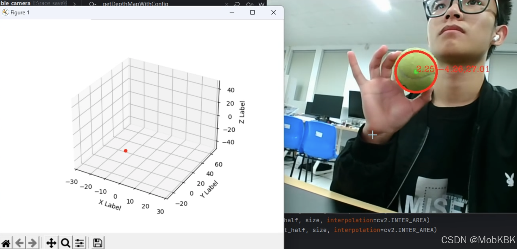
双目获取深度效果展示
琢磨了半天双目是如何使用的
我翻来翻去参考的是这篇博客
https://blog.youkuaiyun.com/weixin_51972728/article/details/125769709
使用matlab进行的双目标定,借助这篇博客中引用的另外一篇大佬的脚本轻松完成了参数提取,十分感谢
下面是一个相机标定后的参数stereoconfig.py文件
import numpy as np


class stereoCamera(object):
    def __init__(self):
        # 左相机内参
        self.cam_matrix_left = np.array([[447.1283, 0, 296.7873], [0, 450.2775, 233.0815],
                                          [0, 0, 1]])
        # 右相机内参
        self.cam_matrix_right = np.array([[445.6631, 0, 313.4459], [0, 447.8569, 234.1087],
                                          [0, 0, 1]])

        # 左右相机畸变系数:[k1, k2, p1, p2, k3]
        self.distortion_l = np.array([[-0.03635, -0.0964, 0.0006, 0.0037, 0.1129]])
        self.distortion_r = np.array([[-0.0670,	0.1509,	0.0007,	0.0024,	-0.3894]])

        # 旋转矩阵
        self.R = np.array([[0.9999,	-0.0004,	0.0063],
                           [0.0004,	0.999977329, -0.0067],
                           [-0.0063,	0.0067,	0.9999]])
        # 平移矩阵
        self.T = np.array([[-6.0397], [-0.0091], [0.0298]])

        # 主点列坐标的差
        self.doffs = 0.0

        # 指示上述内外参是否为经过立体校正后的结果
        self.isRectified = False

代码片
主要的运行代码在下面这个文件中名为track.py:
import cv2
import argparse
import numpy as np
import stereoconfig
import matplotlib.pyplot as plt
from matplotlib.animation import FuncAnimation
from mpl_toolkits.mplot3d import Axes3D
import sys
import matplotlib as mpl
from detect_red import detect_green

mpl.use('TkAgg')

# 初始化坐标
x1,y1,z1=[30],[30],[30]

fig = plt.figure()

# 创建3D坐标轴,设置xyz坐标范围
ax = fig.add_subplot(111, projection='3d')
ax.set_xlim([-30, 30])
ax.set_ylim([-30, 70])
ax.set_zlim([-50, 50])

scatter = ax.scatter(x1, y1, z1, c='r', marker='o')
ax.set_xlabel('X Label')
ax.set_ylabel('Y Label')
ax.set_zlabel('Z Label')


# 图像预处理
def preprocess(img1, img2):
    # 彩色图->灰度图
    if (img1.ndim == 3):
        img1 = cv2.cvtColor(img1, cv2.COLOR_BGR2GRAY)  # 通过OpenCV加载的图像通道顺序是BGR
    if (img2.ndim == 3):
        img2 = cv2.cvtColor(img2, cv2.COLOR_BGR2GRAY)

    # 直方图均衡
    img1 = cv2.equalizeHist(img1)
    img2 = cv2.equalizeHist(img2)
    # 调试用
    # cv2.imshow('img1', img1)
    # cv2.imshow('img2', img2)
    return img1, img2


# 图像去畸变函数
def undistortion(image, camera_matrix, dist_coeff):
    undistortion_image = cv2.undistort(image, camera_matrix, dist_coeff)

    return undistortion_image


# 获取畸变校正和立体校正的映射变换矩阵、重投影矩阵
# @param:config是一个类,存储着双目标定的参数:config = stereoconfig.stereoCamera()
def getRectifyTransform(height, width, config):
    # 读取内参和外参
    left_K = config.cam_matrix_left
    right_K = config.cam_matrix_right
    left_distortion = config.distortion_l
    right_distortion = config.distortion_r
    R = config.R
    T = config.T

    # 计算校正变换
    R1, R2, P1, P2, Q, roi1, roi2 = cv2.stereoRectify(left_K, left_distortion, right_K, right_distortion,
                                                      (width, height), R, T, alpha=0)

    map1x, map1y = cv2.initUndistortRectifyMap(left_K, left_distortion, R1, P1, (width, height), cv2.CV_32FC1)
    map2x, map2y = cv2.initUndistortRectifyMap(right_K, right_distortion, R2, P2, (width, height), cv2.CV_32FC1)
    # 返回各个重投影矩阵,和转换矩阵Q
    return map1x, map1y, map2x, map2y, Q


# 畸变校正和立体校正
def rectifyImage(image1, image2, map1x, map1y, map2x, map2y):
    rectifyed_img1 = cv2.remap(image1, map1x, map1y, cv2.INTER_AREA)
    rectifyed_img2 = cv2.remap(image2, map2x, map2y, cv2.INTER_AREA)
    return rectifyed_img1, rectifyed_img2


# 视差计算
def stereoMatchSGBM(left_image, right_image, down_scale=False):
    # SGBM匹配参数设置
    if left_image.ndim == 2:
        img_channels = 1
    else:
        img_channels = 3
    blockSize = 3
    paraml = {'minDisparity': 0,
              'numDisparities': 300,
              'blockSize': blockSize,
              'P1': 8 * img_channels * blockSize ** 2,
              'P2': 32 * img_channels * blockSize ** 2,
              'disp12MaxDiff': 300,
              'preFilterCap': 63,
              'uniquenessRatio': 15,
              'speckleWindowSize': 100,
              'speckleRange': 1,
              'mode': cv2.STEREO_SGBM_MODE_SGBM_3WAY
              }
    # 构建SGBM对象
    left_matcher = cv2.StereoSGBM_create(**paraml)
    paramr = paraml
    paramr['minDisparity'] = -paraml['numDisparities']
    right_matcher = cv2.StereoSGBM_create(**paramr)

    # 计算视差图
    size = (left_image.shape[1], left_image.shape[0])
    if down_scale == False:
        disparity_left = left_matcher.compute(left_image, right_image)
        disparity_right = right_matcher.compute(right_image, left_image)
    # 如果向下采样
    else:
        left_image_down = cv2.pyrDown(left_image)
        right_image_down = cv2.pyrDown(right_image)
        factor = left_image.shape[1] / left_image_down.shape[1]

        disparity_left_half = left_matcher.compute(left_image_down, right_image_down)
        disparity_right_half = right_matcher.compute(right_image_down, left_image_down)
        disparity_left = cv2.resize(disparity_left_half, size, interpolation=cv2.INTER_AREA)
        disparity_right = cv2.resize(disparity_right_half, size, interpolation=cv2.INTER_AREA)
        disparity_left = factor * disparity_left
        disparity_right = factor * disparity_right

    # 真实视差(因为SGBM算法得到的视差是×16的)
    trueDisp_left = disparity_left.astype(np.float32) / 16.
    trueDisp_right = disparity_right.astype(np.float32) / 16.

    return trueDisp_left, trueDisp_right

# 使用内参计算深度
def getDepthMapWithConfig(config: stereoconfig.stereoCamera, dot_disp1) -> np.ndarray:
    fb = config.cam_matrix_left[0, 0] * (-config.T[0])
    doffs = config.doffs
    disparity = dot_disp1
    depth = fb / (disparity + doffs)
    return depth


vs = cv2.VideoCapture(1)  # 参数1表示第二个摄像头
cv2.namedWindow("Frame")

# 分配摄像头分辨率
vs.set(cv2.CAP_PROP_FRAME_WIDTH, 1280)
vs.set(cv2.CAP_PROP_FRAME_HEIGHT, 480)

# 判断视频是否打开
if (vs.isOpened()):
    print('camera Opened')
else:
    print('摄像头未打开')

OPENCV_OBJECT_TRACKERS = {
    "csrt": cv2.legacy.TrackerCSRT_create, "kcf": cv2.legacy.TrackerKCF_create,
    "boosting": cv2.legacy.TrackerBoosting_create, "mil": cv2.legacy.TrackerMIL_create,
    "tld": cv2.legacy.TrackerTLD_create,
    "medianflow": cv2.legacy.TrackerMedianFlow_create, "mosse": cv2.legacy.TrackerMOSSE_create
}

# trackers = cv2.legacy.MultiTracker_create()

# 读取相机内参和外参
# 使用之前先将标定得到的内外参数填写到stereoconfig.py中的StereoCamera类中
config = stereoconfig.stereoCamera()

# print(config.cam_matrix_left)
map1x, map1y, map2x, map2y, Q = getRectifyTransform(480, 640,
                                                            config)  # 获取用于畸变校正和立体校正的映射矩阵以及用于计算像素空间坐标的重投影矩阵
while True:
    frame = vs.read()
    frame = frame[1]
    if frame is None:
        break
    # 设置右摄像头尺寸
    print('frame.shape', frame.shape)
    right_frame = frame[0:480, 640:1280]
    # 设置左摄像头尺寸
    left_frame = frame[0:480, 0:640]

    # 获取坐标点
    (x,y) = detect_green(left_frame)

    x_old = x
    y_old = y

    if abs(x-x_old)>30:
        x = x_old
        y = y_old

    # 读取一帧图片
    iml = left_frame  # 左图
    imr = right_frame  # 右图
    height, width = iml.shape[0:2]

    # 立体校正

    iml_rectified, imr_rectified = rectifyImage(iml, imr, map1x, map1y, map2x, map2y)
    # print(Q)

    # 立体匹配
    iml_, imr_ = preprocess(iml_rectified, imr_rectified)  # 预处理,一般可以削弱光照不均的影响,不做也可以
    disp, _ = stereoMatchSGBM(iml_, imr_, False)  # 这里传入的是未经立体校正的图像,因为我们使用的middleburry图片已经是校正过的了
    print(disp)
    dot_disp = disp[y][x]
   # cv2.imwrite('disaprity.jpg', disp * 4)

    # xr和yr是右相机相应点的像素坐标
    z = getDepthMapWithConfig(config, dot_disp)
    # 计算3d坐标
    x_camera = (x - config.cam_matrix_left[0][2]) * z / config.cam_matrix_left[0][0]
    y_camera = (y - config.cam_matrix_left[1][2]) * z / config.cam_matrix_left[1][1]
    print('zzz:',z)
    x1 = x_camera
    y1 = y_camera
    z1 = z
    scatter._offsets3d = (x1, -z1, y1)
    text = "{:.2f}".format(float(x_camera)) + ',' + "{:.2f}".format(float(y_camera)) + ',' + "{:.2f}".format(float(z))
    cv2.putText(left_frame, text, (x, y), cv2.FONT_HERSHEY_COMPLEX, 0.6, (0, 0, 255), 1)

    # 显示两个框
    cv2.imshow("right", right_frame)
    cv2.imshow('Frame', left_frame)
    plt.show(block=False)
    plt.pause(0.005)
    plt.ion()  # 开启交互模式

    # 按键判断是否设置新的目标
    key = cv2.waitKey(10) & 0xFF
    # if key == ord('s'):
    #     box = cv2.selectROI('Frame', left_frame, fromCenter=False, showCrosshair=True)
    #     tracker = cv2.legacy.TrackerCSRT_create()
    #     print(type(box), type(box[0]), box[1], box)
    #     trackers.add(tracker, left_frame, box)
    if key == 27:
        break
vs.release()
cv2.destroyAllWindows()
其中用到的detect_red.py文件如下:
import cv2
import numpy as np

def detect_green(img):
    hsv = cv2.cvtColor(img, cv2.COLOR_BGR2HSV)
    lower_red = np.array([35, 64, 64])
    upper_red = np.array([77, 255, 255])
    mask = cv2.inRange(hsv, lower_red, upper_red)
    mask1 = cv2.morphologyEx(mask, cv2.MORPH_OPEN, np.ones((5, 5), np.uint8))
    gaussian = cv2.GaussianBlur(mask1, (5, 5), 0)

    circles = cv2.HoughCircles(
        gaussian,  # 输入的灰度图像
        cv2.HOUGH_GRADIENT,  # 使用霍夫梯度方法
        dp=1,  # 1:累加器的分辨率
        minDist=30,  # 圆心之间的最小距离
        param1=50,  # 边缘检测的阈值
        param2=15,  # 找到圆的阈值
        minRadius=30,  # 最小圆半径
        maxRadius=500  # 最大圆半径
    )
    if circles is not None:
        # 将圆的坐标和半径从浮点型转换为整数
        circles = np.round(circles[0, :]).astype("int")

        # 绘制检测到的圆
        (x, y, r) =circles[0]
        # 画出圆心
        cv2.circle(img, (x, y), 5, (0, 255, 0), -1)
        # 画出圆的轮廓
        cv2.circle(img, (x, y), r, (0, 0, 255), 3)
        return (x, y)
    else:
        return (0,0)
当前还是在自己电脑上运行,后续其他细节优化后会部署在rdkx5上。
当前的思路是:先通过深度学习获得手部位置,在计算3d位置信息,然后通过手上的加速度传感器获得一个姿态,显示在一张3d图上
深度学习部分还在研究中,后面有进展会更新发布
加速度传感器比较简单,选择在最后面进行


 1719
1719

 被折叠的 条评论
为什么被折叠?
被折叠的 条评论
为什么被折叠?
 到【灌水乐园】发言


